Page 287 of 3870

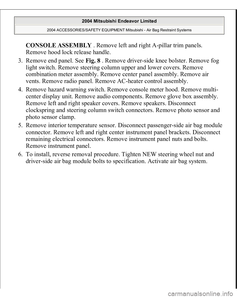
CONSOLE ASSEMBL
Y . Remove left and right A-pillar trim panels.
Remove hood lock release handle.
3. Remove end panel. See Fig. 8
. Remove driver-side knee bolster. Remove fog
light switch. Remove steering column upper and lower covers. Remove
combination meter assembly. Remove center panel assembly. Remove air
vents. Remove radio panel. Remove AC-heater control assembly.
4. Remove hazard warning switch. Remove console meter hood. Remove multi-
center display unit. Remove audio components. Remove glove box assembly.
Remove left and right speaker covers. Remove speakers. Disconnect
clockspring and steering column switch connectors. Remove photo sensor and
photo sensor clamp.
5. Remove interior temperature sensor. Disconnect passenger-side air bag module
connector. Remove left and right center instrument panel brackets. Disconnect
remaining electrical connectors. Remove instrument panel nuts and bolts.
Remove instrument panel.
6. To install, reverse removal procedure. Tighten NEW steering wheel nut and
drive
r-side air ba
g module bolts to s
pecification. Activate air ba
g system.
2004 Mitsubishi Endeavor Limited
2004 ACCESSORIES/SAFETY EQUIPMENT Mitsubishi - Air Bag Restraint Systems
Page 1625 of 3870

2004 BODY & ACCESSORIES
Radio With Tape Player & Cd Player - Endeavor
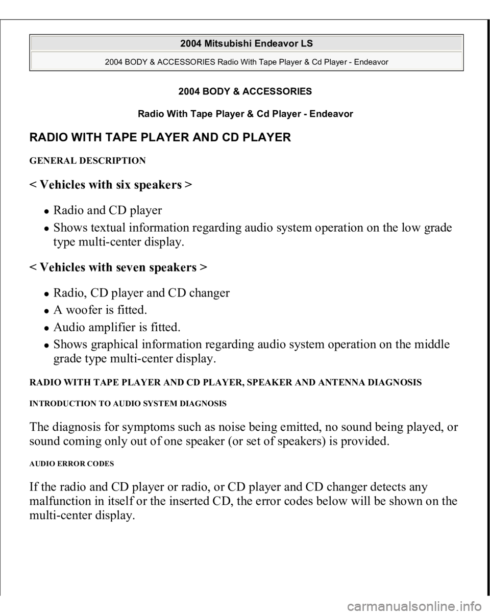
RADIO WITH TAPE PLAYER AND CD PLAYER GENERAL DESCRIPTION < Vehicles with six speakers >
Radio and CD player Shows textual information regarding audio system operation on the low grade
type multi-center display.
< Vehicles with seven speakers > Radio, CD player and CD changer A woofer is fitted. Audio amplifier is fitted. Shows graphical information regarding audio system operation on the middle
grade type multi-center display.
RADIO WITH TAPE PLAYER AND CD PLAYER, SPEAKER AND ANTENNA DIAGNOSIS INTRODUCTION TO AUDIO SYSTEM DIAGNOSIS The diagnosis for symptoms such as noise being emitted, no sound being played, or
sound coming only out of one speaker (or set of speakers) is provided. AUDIO ERROR CODES If the radio and CD player or radio, or CD player and CD changer detects any
malfunction in itself or the inserted CD, the error codes below will be shown on the
multi-center dis
play.
2004 Mitsubishi Endeavor LS
2004 BODY & ACCESSORIES Radio With Tape Player & Cd Player - Endeavor
2004 Mitsubishi Endeavor LS
2004 BODY & ACCESSORIES Radio With Tape Player & Cd Player - Endeavor
Page 1642 of 3870

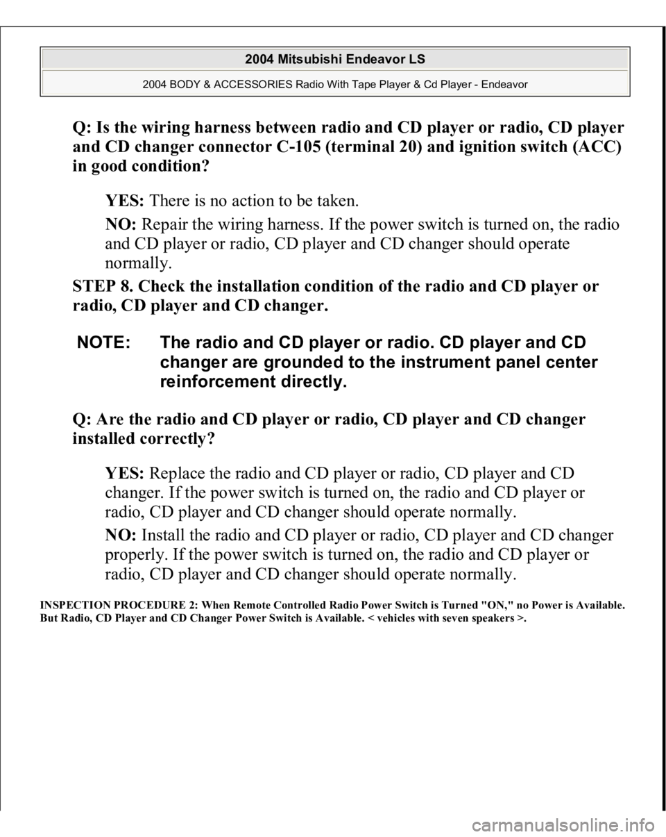
Q: Is the wiring harness between radio and CD player or radio, CD player
and CD changer connector C-105 (terminal 20) and ignition switch (ACC)
in good condition?
YES: There is no action to be taken.
NO: Repair the wiring harness. If the power switch is turned on, the radio
and CD player or radio, CD player and CD changer should operate
normally.
STEP 8. Check the installation condition of the radio and CD player or
radio, CD player and CD changer.
Q: Are the radio and CD player or radio, CD player and CD changer
installed correctly?
YES: Replace the radio and CD player or radio, CD player and CD
changer. If the power switch is turned on, the radio and CD player or
radio, CD player and CD changer should operate normally.
NO: Install the radio and CD player or radio, CD player and CD changer
properly. If the power switch is turned on, the radio and CD player or
radio, CD player and CD changer should operate normally.
INSPECTION PROCEDURE 2: When Remote Controlled Radio Power Switch is Turned "ON," no Power is Available.
But Radio, CD Player and CD Changer Power Switch is Available. < vehicles with seven speakers >.
NOTE: The radio and CD player or radio. CD player and CD
changer are grounded to the instrument panel center
reinforcement directly.
2004 Mitsubishi Endeavor LS
2004 BODY & ACCESSORIES Radio With Tape Player & Cd Player - Endeavor
Page 1666 of 3870
Fig. 38: Switch Position Table
Courtesy of MITSUBISHI MOTOR SALES OF AMERICA.
Q: Are the resistance at the right remote controlled radio switch normal?
YES: Replace the radio, CD player and CD changer.
NO: Replace the remote controlled radio switch (RH).
INSPECTION PROCEDURE 3: The System does not Recognize the Remote Controlled Radio Switch (RH) Only. <
vehicles with seven speakers >. CIRCUIT OPERATION Refer to INSPECTION PROCEDURE 2
.
TECHNICAL DESCRIPTION (COMMENT) Refer to INSPECTION PROCEDURE 2
.
TROUBLESHOOTING HINTS Refer to INSPECTION PROCEDURE 2
.
DIAGNOSIS Required Special Tool:
MB991223: Harness set
2004 Mitsubishi Endeavor LS
2004 BODY & ACCESSORIES Radio With Tape Player & Cd Player - Endeavor
Page 1670 of 3870
Fig. 42: Identifying Connector C
-301 C
-303
Courtesy of MITSUBISHI MOTOR SALES OF AMERICA.
Q: Are the wiring harness between remote controlled radio switch (RH)
connector C-301 (terminals 1 and 2) and clock spring connector C-303
(terminals 4 and 5) in good condition?
YES: The procedure is complete.
NO: Repair the wiring harness. The remote controlled radio switch (RH)
should work normally.
INSPECTION PROCEDURE 4: The System does not Recognize the Remote Controlled Radio Switch (LH) Only. <
vehicles with seven speakers >. CIRCUIT OPERATION Refer to INSPECTION PROCEDURE 2
.
2004 Mitsubishi Endeavor LS
2004 BODY & ACCESSORIES Radio With Tape Player & Cd Player - Endeavor
Page 1680 of 3870
Fig. 50: Identifying Connector C
-11
Courtesy of MITSUBISHI MOTOR SALES OF AMERICA.
Q: Is audio amplifier connector C-11 in good condition?
YES: Go to Step 3.
NO: Repair or replace the damaged component(s). The speakers should
sound.
STEP 3. Check the wiring harness between audio amplifier connector C-
11 (terminal 6 and 16) and the battery.
2004 Mitsubishi Endeavor LS
2004 BODY & ACCESSORIES Radio With Tape Player & Cd Player - Endeavor
Page 1683 of 3870
Fig. 52: Identifying Connector C
-31
Courtesy of MITSUBISHI MOTOR SALES OF AMERICA.
Q: Is the wiring harness between audio amplifier connector C-11
(terminal 6 and 16) and the battery in good condition?
YES: There is no action to be taken.
NO: Repair the wiring harness. The speakers should sound.
STEP 4. Measure the resistance at audio amplifier connector C-11 in
order to check the ground circuit to the audio amplifier.
1. Disconnect audio amplifier connector C-11, and measure at the wiring
harness side.
2004 Mitsubishi Endeavor LS
2004 BODY & ACCESSORIES Radio With Tape Player & Cd Player - Endeavor
Page 1685 of 3870
STEP 5. Check audio amplifier connector C-11 for loose, corroded or
damaged terminals, or terminals pushed back in the connector.
Fig. 55: Identifying Connector C
-11
Courtesy of MITSUBISHI MOTOR SALES OF AMERICA.
Q: Is audio amplifier connector C-11 in good condition?
YES: Go to Step 6.
NO: Repair or replace the damaged component(s). The speakers should
sound.
STEP 6. Check the wiring harness between audio amplifier connector C-
2004 Mitsubishi Endeavor LS
2004 BODY & ACCESSORIES Radio With Tape Player & Cd Player - Endeavor