Page 295 of 3870
3. To install, reverse removal procedure. Tighten front seat nuts and bolts to
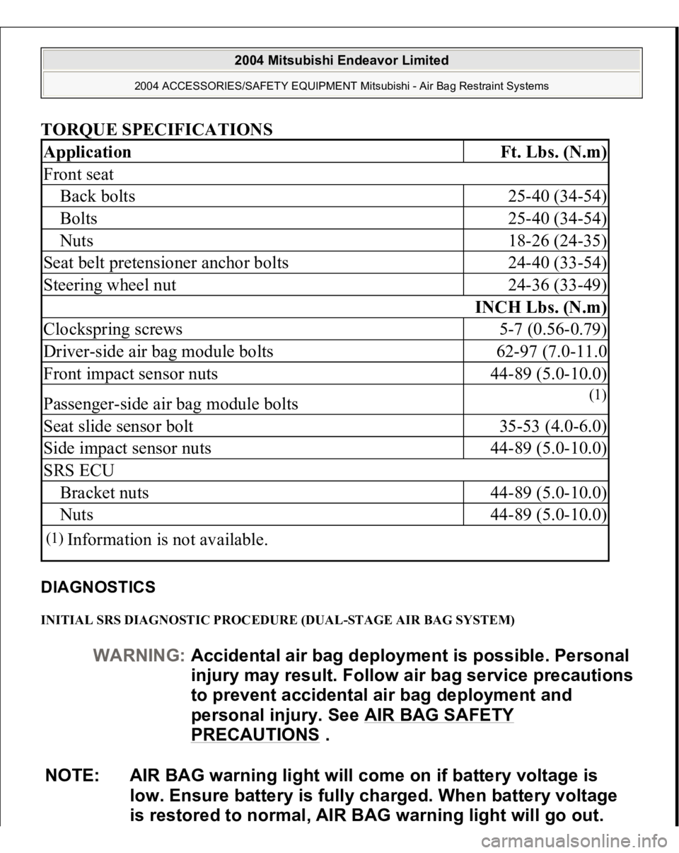
specification. See TORQUE SPECIFICATIONS
. Activate air bag system.
SIDE IMPACT SENSOR Removal & Installation 1. Before proceeding, see AIR BAG SAFETY PRECAUTIONS
. Disable air
bag system. See DISABLING & ACTIVATING AIR BAG SYSTEM
.
2. Remove appropriate B-pillar trim panel. Remove seat belt pretensioner. See
SEAT BELT PRETENSIONER
. Remove side impact sensor nuts. See Fig.
14 . Disconnect side impact sensor electrical connector. Remove side impact
sensor.
3. To install, reverse removal procedure. Tighten side impact sensor nuts and seat
belt pretensioner anchor bolts to specification. See TORQUE SPECIFICATIONS
. Activate air bag system.
Fig. 14: Identifying Side Impact Sensor
Courtesy of MITSUBISHI MOTOR SALES OF AMERICA.
SRS ELECTRONIC CONTROL UNIT (SRS ECU)
2004 Mitsubishi Endeavor Limited
2004 ACCESSORIES/SAFETY EQUIPMENT Mitsubishi - Air Bag Restraint Systems
Page 296 of 3870
Removal & Installation (Single Stage AIR Bag System
)
1. Before proceeding, see AIR BAG SAFETY PRECAUTIONS
. Turn ignition
off. Disable air bag system. See DISABLING & ACTIVATING AIR BAG
SYSTEM
.
2. Remove center console. See FLOOR CONSOLE ASSEMBLY
. Disconnect
SRS ECU connectors. Remove SRS ECU nuts. Remove SRS ECU. See Fig.
15 . Remove nuts from SRS ECU bracket. Remove SRS ECU bracket.
3. To install, reverse removal procedure. Tighten SRS ECU bracket nuts and SRS
ECU nuts to specification. See TORQUE SPECIFICATIONS
. Activate air
bag system.
Fig. 15: Identifying Single
-stage SRS Electronic Control Unit (SRS ECU)
-
single
-stage Air Bag System
Courtes
y of MITSUBISHI MOTOR SALES OF AMERICA
.
2004 Mitsubishi Endeavor Limited
2004 ACCESSORIES/SAFETY EQUIPMENT Mitsubishi - Air Bag Restraint Systems
Page 297 of 3870
Removal & Installation (Dual-stage AIR Bag System)1. Before proceeding, see AIR BAG SAFETY PRECAUTIONS
. Turn ignition
off. Disable air bag system. See DISABLING & ACTIVATING AIR BAG
SYSTEM
.
2. Remove center console. See FLOOR CONSOLE ASSEMBLY
. Disconnect
SRS ECU connectors. Remove SRS ECU nuts. Remove SRS ECU. See Fig.
16 .
3. To install, reverse removal procedure. Tighten SRS ECU nuts to specification.
See TORQUE SPECIFICATIONS
. Activate air bag system.
Fig. 16: Identifying SRS Electronic Control Unit (SRS ECU)
-dual
-stage Air
Bag System
Courtesy of MITSUBISHI MOTOR SALES OF AMERICA.
2004 Mitsubishi Endeavor Limited
2004 ACCESSORIES/SAFETY EQUIPMENT Mitsubishi - Air Bag Restraint Systems
Page 298 of 3870
ADJUSTMENTS CENTERING CLOCKSPRING (DUAL-STAGE AIR BAG SYSTEM) Turn clockspring fully clockwise, then turn counterclockwise about 3 turns to align
mating marks. See Fig. 17
. Clockspring is now centered.
Fig. 17: Aligning Clockspring Mating Marks (Single
-sta
ge Clocks
prin
g Shown,
Dual
-stage Clockspring Is Similar)
Courtesy of MITSUBISHI MOTOR SALES OF AMERICA.
WIRE REPAIR DO NOT repair SRS wiring harness or connectors. If SRS wiring or harness
connectors are faulty, replace wiring harness. TORQUE SPECIFICATION
S
2004 Mitsubishi Endeavor Limited
2004 ACCESSORIES/SAFETY EQUIPMENT Mitsubishi - Air Bag Restraint Systems
Page 299 of 3870

TORQUE SPECIFICATIONS DIAGNOSTICS INITIAL SRS DIAGNOSTIC PROCEDURE (DUAL-STAGE AIR BAG SYSTEM) Application
Ft. Lbs. (N.m)
Front seatBack bolts
25-40 (34-54)
Bolts
25-40 (34-54)
Nuts
18-26 (24-35)
Seat belt pretensioner anchor bolts
24-40 (33-54)
Steering wheel nut
24-36 (33-49)
INCH Lbs. (N.m)
Clockspring screws
5-7 (0.56-0.79)
Driver-side air bag module bolts
62-97 (7.0-11.0
Front impact sensor nuts
44-89 (5.0-10.0)
Passenger-side air bag module bolts
(1)
Seat slide sensor bolt
35-53 (4.0-6.0)
Side impact sensor nuts
44-89 (5.0-10.0)
SRS ECUBracket nuts
44-89 (5.0-10.0)
Nuts
44-89 (5.0-10.0)
(1)
Information is not available.
WARNING:Accidental air bag deployment is possible. Personal
in
jury ma
y result. Follow air ba
g service precautions
to prevent accidental air bag deployment and
personal injury. See AIR BAG SAFETY
PRECAUTIONS
.
NOTE: AIR BAG warning light will come on if battery voltage is
low. Ensure battery is fully charged. When battery voltage
is restored to normal, AIR BAG warning light will go out.
2004 Mitsubishi Endeavor Limited
2004 ACCESSORIES/SAFETY EQUIPMENT Mitsubishi - Air Bag Restraint Systems
Page 456 of 3870

2004 TRANSMISSION
Automatic Transaxle Overhaul - Endeavor
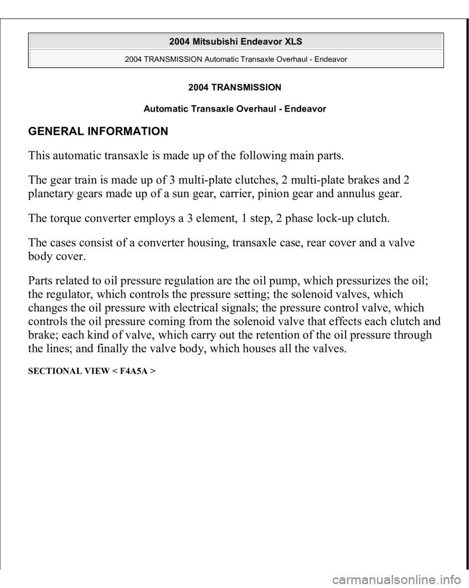
GENERAL INFORMATION This automatic transaxle is made up of the following main parts.
The gear train is made up of 3 multi-plate clutches, 2 multi-plate brakes and 2
planetary gears made up of a sun gear, carrier, pinion gear and annulus gear.
The torque converter employs a 3 element, 1 step, 2 phase lock-up clutch.
The cases consist of a converter housing, transaxle case, rear cover and a valve
body cover.
Parts related to oil pressure regulation are the oil pump, which pressurizes the oil;
the regulator, which controls the pressure setting; the solenoid valves, which
changes the oil pressure with electrical signals; the pressure control valve, which
controls the oil pressure coming from the solenoid valve that effects each clutch and
brake; each kind of valve, which carry out the retention of the oil pressure through
the lines; and finally the valve body, which houses all the valves. SECTIONAL VIEW < F4A5A >
2004 Mitsubishi Endeavor XLS
2004 TRANSMISSION Automatic Transaxle Overhaul - Endeavor
2004 Mitsubishi Endeavor XLS
2004 TRANSMISSION Automatic Transaxle Overhaul - Endeavor
Page 464 of 3870
Fig. 8: Exploded View And Torque Specification Automatic Transaxle System (1 Of 5 ))
Courtesy of MITSUBISHI MOTOR SALES OF AMERICA
.
2004 Mitsubishi Endeavor XLS
2004 TRANSMISSION Automatic Transaxle Overhaul - Endeavor
Page 465 of 3870
Fig. 9: Exploded View And Torque Specification Automatic Transaxle System (2 Of 5)
Courtesy of MITSUBISHI MOTOR SALES OF AMERICA.
2004 Mitsubishi Endeavor XLS
2004 TRANSMISSION Automatic Transaxle Overhaul - Endeavor