2004 MITSUBISHI ENDEAVOR Battery terminals
[x] Cancel search: Battery terminalsPage 362 of 3870
retrieved, system is normal at this time.
DTCB1413: PASSENGER-SIDE AIR BAG MODULE FIRST-STAGE SHORT TO GROUND 1. Connect scan tool to Data Link Connector (DLC). See INITIAL SRS
DIAGNOSTIC PROCEDURE
under DIAGNOSTICS. If scan tool is able to
diagnose CAN bus lines and CAN bus lines are satisfactory, go to next step. If
scan tool cannot diagnose CAN bus lines, repair CAN bus lines. Go to next
step.
2. Erase, then retrieve DTCs. Turn ignition off. If DTC B1413 is retrieved, go to
next step. If DTC B1413 is not retrieved, an intermittent condition may exist.
3. Disconnect negative battery cable. Disconnect passenger-side air bag module
connector C-09. See PASSENGER
-SIDE AIR BAG MODULE
under
REMOVAL & INSTALLATION. See Fig. 30
. Connect Load Resistor
(MB991865) to Load Resistor Adapter (MB991866). Insert load resistor
adapter leads into harness-side terminals No. 1 (Yellow/Green wire) and No. 2
(Yellow/Red wire) of connector C-09. See Fig. 35
. Connect negative battery
cable. Erase, then retrieve DTCs. If DTC B1413 is retrieved, go to next step. If
DTC B1413 is not retrieved, replace passenger-side air bag module. Go to step
5 .
4. Disconnect negative battery cable. Remove load resistor and load resistor
adapter from passenger-side air bag module connector C-09. Disconnect SRS
ECU connector C-26. See SRS ELECTRONIC CONTROL UNIT (SRS
ECU)
under REMOVAL & INSTALLATION. Release SRS ECU connector
shorting bar using a cable tie. Measure resistance between ground and SRS
ECU connector terminals No. 27 (Yellow/Green wire) and No. 28 (Yellow/Red
wire). See Fig. 33
. If resistance is not infinite, go to next step. If resistance is
infinite, reconnect SRS components. Erase, then retrieve DTCs. If DTC B1413
is retrieved, replace SRS ECU. Go to step 6 .
5. Replace wire harness between SRS ECU and passenger-side air bag module.
Go to next step.
6. Reconnect all SRS components. Activate air bag system. Using scan tool,
retrieve DTCs. If DTC B1412 is retrieved, go to step 1 . If DTC B1412 is not
retrieved, system is normal at this time.
DTC B1414: PASSENGE
R-SIDE AIR BAG MODULE FIRST-STAGE ACTIVATION CIRCUIT
2004 Mitsubishi Endeavor Limited
2004 ACCESSORIES/SAFETY EQUIPMENT Mitsubishi - Air Bag Restraint Systems
Page 367 of 3870
correctly, reconnect correctly. Go to step 9 .
5. Disconnect negative battery cable. Disconnect, then reconnect SRS ECU
connector C-25 and passenger side impact air bag module connector D-31. See
SIDE IMPACT AIR BAG MODULE
under REMOVAL &
INSTALLATION. Connect negative battery cable. Using scan tool, erase, then
retrieve DTCs. If DTC B1420 is retrieved, go to next step. If DTC B1420 is
not retrieved, intermittent condition may have existed.
6. Disconnect negative battery cable. Disconnect passenger side impact air bag
module connector D-31. Connect Load Resistor (MB991865) to Load Resistor
Adapter (MB991866). Insert load resistor adapter leads into harness-side
terminals No. 1 (Yellow wire) and No. 2 (Yellow/Black wire) of connector D-
31. See Fig. 36
. Connect negative battery cable. Erase, then retrieve DTCs. If
DTC B1420 is retrieved, go to next step. If DTC B1420 is not retrieved,
replace passenger side impact air bag module.
7. Disconnect negative battery cable. Remove load resistor and load resistor
adapter from passenger side impact air bag module connector D-31.
Disconnect SRS ECU connector C-25. Release SRS ECU connector shorting
bar using a cable tie. Measure resistance between SRS ECU connector
terminals No. 58 (Yellow wire) and No. 57 (Yellow/Black wire). See Fig. 33
.
If continuity exits, go to next step. If continuity does not exist, reconnect SRS
components. Erase, then retrieve DTCs. If DTC B1420 is retrieved, replace
SRS ECU. Go to step 9 .
8. Replace wire harness between SRS ECU and passenger side impact air bag
module. Go to next step.
9. Reconnect all SRS components. Activate air bag system. Using scan tool,
retrieve DTCs. If DTC B1420 is retrieved, go to step 1 . If DTC B1420 is not
retrieved, s
ystem is normal at this time.
2004 Mitsubishi Endeavor Limited
2004 ACCESSORIES/SAFETY EQUIPMENT Mitsubishi - Air Bag Restraint Systems
Page 368 of 3870
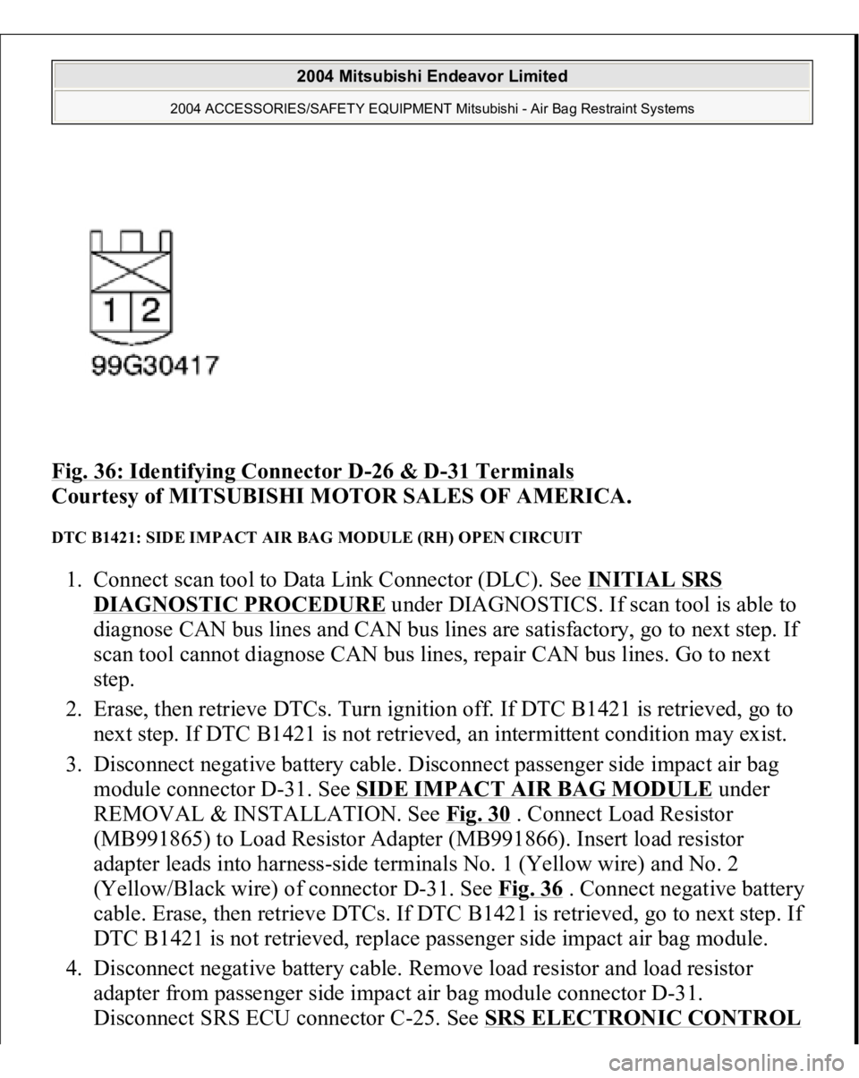
Fig. 36: Identifying Connector D
-26 & D
-31 Terminals
Courtesy of MITSUBISHI MOTOR SALES OF AMERICA.
DTC B1421: SIDE IMPACT AIR BAG MODULE (RH) OPEN CIRCUIT 1. Connect scan tool to Data Link Connector (DLC). See INITIAL SRS
DIAGNOSTIC PROCEDURE
under DIAGNOSTICS. If scan tool is able to
diagnose CAN bus lines and CAN bus lines are satisfactory, go to next step. If
scan tool cannot diagnose CAN bus lines, repair CAN bus lines. Go to next
step.
2. Erase, then retrieve DTCs. Turn ignition off. If DTC B1421 is retrieved, go to
next step. If DTC B1421 is not retrieved, an intermittent condition may exist.
3. Disconnect negative battery cable. Disconnect passenger side impact air bag
module connector D-31. See SIDE IMPACT AIR BAG MODULE
under
REMOVAL & INSTALLATION. See Fig. 30
. Connect Load Resistor
(MB991865) to Load Resistor Adapter (MB991866). Insert load resistor
adapter leads into harness-side terminals No. 1 (Yellow wire) and No. 2
(Yellow/Black wire) of connector D-31. See Fig. 36
. Connect negative battery
cable. Erase, then retrieve DTCs. If DTC B1421 is retrieved, go to next step. If
DTC B1421 is not retrieved, replace passenger side impact air bag module.
4. Disconnect negative battery cable. Remove load resistor and load resistor
adapter from passenger side impact air bag module connector D-31.
Disconnect SRS ECU connector
C-25. See SRS ELECTRONIC CONTROL
2004 Mitsubishi Endeavor Limited
2004 ACCESSORIES/SAFETY EQUIPMENT Mitsubishi - Air Bag Restraint Systems
Page 369 of 3870
UNIT (SRS ECU)
under REMOVAL & INSTALLATION. Release SRS ECU
connector shorting bar using a cable tie. Measure resistance of Yellow wire
between SRS ECU connector C-25, terminal No. 58 and terminal No. 1 of
connector D-31. See Fig. 33
. Measure resistance of Yellow/Black wire
between SRS ECU connector C-25, terminal No. 57 and terminal No. 2 of
connector D-31. If resistance is 2 ohms or more in each wire, go to next step. If
resistance is less than 2 ohms in each wire, reconnect SRS components. Erase,
then retrieve DTCs. If DTC B1421 is retrieved, replace SRS ECU. Go to step
6 .
5. Replace wire harness between SRS ECU and passenger side impact air bag
module. Go to next step.
6. Reconnect all SRS components. Activate air bag system. Using scan tool,
retrieve DTCs. If DTC B1421 is retrieved, go to step 1 . If DTC B1421 is not
retrieved, system is normal at this time.
DTC B1422: SIDE IMPACT AIR BAG MODULE (RH) SHORT TO VOLTAGE 1. Connect scan tool to Data Link Connector (DLC). See INITIAL SRS
DIAGNOSTIC PROCEDURE
under DIAGNOSTICS. If scan tool is able to
diagnose CAN bus lines and CAN bus lines are satisfactory, go to next step. If
scan tool cannot diagnose CAN bus lines, repair CAN bus lines. Go to next
step.
2. Erase, then retrieve DTCs. Turn ignition off. If DTC B1422 is retrieved, go to
next step. If DTC B1422 is not retrieved, an intermittent condition may exist.
3. Disconnect negative battery cable. Disconnect passenger side impact air bag
module connector D-31. See SIDE IMPACT AIR BAG MODULE
under
REMOVAL & INSTALLATION. See Fig. 30
. Connect Load Resistor
(MB991865) to Load Resistor Adapter (MB991866). Insert load resistor
adapter leads into harness-side terminals No. 1 (Yellow wire) and No. 2
(Yellow/Black wire) of connector D-31. See Fig. 36
. Connect negative battery
cable. Erase, then retrieve DTCs. If DTC B1422 is retrieved, go to next step. If
DTC B1422 is not retrieved, replace passenger side impact air bag module.
4. Disconnect negative battery cable. Remove load resistor and load resistor
adapter from passenger side impact air bag module connector D-31.
Disconnect SRS ECU connector
C-25. See SRS ELECTRONIC CONTROL
2004 Mitsubishi Endeavor Limited
2004 ACCESSORIES/SAFETY EQUIPMENT Mitsubishi - Air Bag Restraint Systems
Page 370 of 3870
UNIT (SRS ECU)
under REMOVAL & INSTALLATION. Release SRS ECU
connector shorting bar using a cable tie. Measure voltage between ground and
SRS ECU connector C-25, terminal No. 58 (Yellow wire). See Fig. 33
.
Measure voltage between ground and SRS ECU connector C-25, terminal No.
57 (Yellow/Black wire). If voltage is measured at either terminal, go to next
step. If voltage is not measured at both terminals, reconnect SRS components.
Erase, then retrieve DTCs. If DTC B1422 is retrieved, replace SRS ECU. Go to
step 6 .
5. Replace wire harness between SRS ECU and passenger side impact air bag
module. Go to next step.
6. Reconnect all SRS components. Activate air bag system. Using scan tool,
retrieve DTCs. If DTC B1422 is retrieved, go to step 1 . If DTC B1422 is not
retrieved, system is normal at this time.
DTC B1423: SIDE IMPACT AIR BAG MODULE (RH) SHORT TO GROUND 1. Connect scan tool to Data Link Connector (DLC). See INITIAL SRS
DIAGNOSTIC PROCEDURE
under DIAGNOSTICS. If scan tool is able to
diagnose CAN bus lines and CAN bus lines are satisfactory, go to next step. If
scan tool cannot diagnose CAN bus lines, repair CAN bus lines. Go to next
step.
2. Erase, then retrieve DTCs. Turn ignition off. If DTC B1423 is retrieved, go to
next step. If DTC B1423 is not retrieved, an intermittent condition may exist.
3. Disconnect negative battery cable. Disconnect passenger side impact air bag
module connector D-31. See SIDE IMPACT AIR BAG MODULE
under
REMOVAL & INSTALLATION. See Fig. 30
. Connect Load Resistor
(MB991865) to Load Resistor Adapter (MB991866). Insert load resistor
adapter leads into harness-side terminals No. 1 (Yellow wire) and No. 2
(Yellow/Black wire) of connector D-31. See Fig. 36
. Connect negative battery
cable. Erase, then retrieve DTCs. If DTC B1423 is retrieved, go to next step. If
DTC B1423 is not retrieved, replace passenger side impact air bag module.
4. Disconnect negative battery cable. Remove load resistor and load resistor
adapter from passenger side impact air bag module connector D-31.
Disconnect SRS ECU connector C-25. See SRS ELECTRONIC CONTROL
UNIT (SRS ECU)
under REMOVAL & INSTALLATION. Release SRS ECU
2004 Mitsubishi Endeavor Limited
2004 ACCESSORIES/SAFETY EQUIPMENT Mitsubishi - Air Bag Restraint Systems
Page 376 of 3870
DTC B1430 is retrieved, go to next step. If DTC B1430 is not retrieved,
intermittent condition may have existed.
6. Disconnect negative battery cable. Disconnect driver side impact air bag
module connector D-26. See SIDE IMPACT AIR BAG MODULE
under
REMOVAL & INSTALLATION. Connect Load Resistor (MB991865) to
Load Resistor Adapter (MB991866). Insert load resistor adapter leads into
harness-side terminals No. 1 (Yellow/Green wire) and No. 2 (Yellow/Red
wire) of connector D-26. See Fig. 36
. Connect negative battery cable. Erase,
then retrieve DTCs. If DTC B1430 is retrieved, go to next step. If DTC B1430
is not retrieved, replace driver side impact air bag module.
7. Disconnect negative battery cable. Remove load resistor and load resistor
adapter from driver side impact air bag module connector D-26. Disconnect
SRS ECU connector C-40. Release SRS ECU connector shorting bar using a
cable tie. Measure resistance between SRS ECU connector C-40, terminals No.
9 (Yellow/Green wire) and No. 10 (Yellow/Red wire). See Fig. 33
. If
continuity exits, go to next step. If continuity does not exist, reconnect SRS
components. Erase, then retrieve DTCs. If DTC B1430 is retrieved, replace
SRS ECU. Go to step 9 .
8. Replace wire harness between SRS ECU and driver side impact air bag
module. Go to next step.
9. Reconnect all SRS components. Activate air bag system. Using scan tool,
retrieve DTCs. If DTC B1430 is retrieved, go to step 1 . If DTC B1430 is not
retrieved, system is normal at this time.
DTCB1431: SIDE IMPACT AIR BAG MODULE (LH) OPEN CIRCUIT 1. Connect scan tool to Data Link Connector (DLC). See INITIAL SRS
DIAGNOSTIC PROCEDURE
under DIAGNOSTICS. If scan tool is able to
diagnose CAN bus lines and CAN bus lines are satisfactory, go to next step. If
scan tool cannot diagnose CAN bus lines, repair CAN bus lines. Go to next
step.
2. Erase, then retrieve DTCs. Turn ignition off. If DTC B1431 is retrieved, go to
next step. If DTC B1431 is not retrieved, an intermittent condition may exist.
3. Disconnect negative battery cable. Disconnect driver side impact air bag
module connector D-26. See SIDE IMPACT AIR BAG MODULE
unde
r
2004 Mitsubishi Endeavor Limited
2004 ACCESSORIES/SAFETY EQUIPMENT Mitsubishi - Air Bag Restraint Systems
Page 377 of 3870
REMOVAL & INSTALLATION. See Fig. 30
. Connect Load Resistor
(MB991865) to Load Resistor Adapter (MB991866). Insert load resistor
adapter leads into harness-side terminals No. 1 (Yellow/Green wire) and No. 2
(Yellow/Red wire) of connector D-26. See Fig. 36
. Connect negative battery
cable. Erase, then retrieve DTCs. If DTC B1431 is retrieved, go to next step. If
DTC B1431 is not retrieved, replace driver side impact air bag module. Go to
step 6 .
4. Disconnect negative battery cable. Remove load resistor and load resistor
adapter from driver side impact air bag module connector D-24. Disconnect
SRS ECU connector C-40. See SRS ELECTRONIC CONTROL UNIT
(SRS ECU)
under REMOVAL & INSTALLATION. Release SRS ECU
connector shorting bar using a cable tie. Measure resistance of Yellow/Green
wire between SRS ECU connector C-40, terminal No. 9 and terminal No. 1 of
connector D-26. See Fig. 33
. Measure resistance of Yellow/Red wire between
SRS ECU connector C-40, terminal No. 10 and terminal No. 2 of connector D-
26. If resistance is 2 ohms or more in either wire, go to next step. If resistance
is less than 2 ohms in both wires, reconnect SRS components. Erase, then
retrieve DTCs. If DTC B1431 is retrieved, replace SRS ECU. Go to step 6 .
5. Replace wire harness between SRS ECU and driver side impact air bag
module. Go to next step.
6. Reconnect all SRS components. Activate air bag system. Using scan tool,
retrieve DTCs. If DTC B1431 is retrieved, go to step 1 . If DTC B1431 is not
retrieved, system is normal at this time.
DTC B1432: SIDE IMPACT AIR BAG MODULE (LH) SHORT TO VOLTAGE 1. Connect scan tool to Data Link Connector (DLC). See INITIAL SRS
DIAGNOSTIC PROCEDURE
under DIAGNOSTICS. If scan tool is able to
diagnose CAN bus lines and CAN bus lines are satisfactory, go to next step. If
scan tool cannot diagnose CAN bus lines, repair CAN bus lines. Go to next
step.
2. Erase, then retrieve DTCs. Turn ignition off. If DTC B1432 is retrieved, go to
next step. If DTC B1432 is not retrieved, an intermittent condition may exist.
3. Disconnect negative battery cable. Disconnect driver side impact air bag
module connector D-26. See SIDE IMPACT AIR BAG MODULE
unde
r
2004 Mitsubishi Endeavor Limited
2004 ACCESSORIES/SAFETY EQUIPMENT Mitsubishi - Air Bag Restraint Systems
Page 378 of 3870
REMOVAL & INSTALLATION. See Fig. 30
. Connect Load Resistor
(MB991865) to Load Resistor Adapter (MB991866). Insert load resistor
adapter leads into harness-side terminals No. 1 (Yellow/Green wire) and No. 2
(Yellow/Red wire) of connector D-26. See Fig. 36
. Connect negative battery
cable. Erase, then retrieve DTCs. If DTC B1432 is retrieved, go to next step. If
DTC B1432 is not retrieved, replace driver side impact air bag module. Go to
step 6 .
4. Disconnect negative battery cable. Remove load resistor and load resistor
adapter from driver side impact air bag module connector D-26. Disconnect
SRS ECU connector C-40. Release SRS ECU connector shorting bar using a
cable tie. Measure voltage between ground and SRS ECU connector C-40,
terminals No. 9 (Yellow/Green wire) and No. 10 (Yellow/Red wire). See Fig.
33 . If voltage is measured at either terminal, go to next step. If voltage is not
measured at both terminals, reconnect SRS components. Erase, then retrieve
DTCs. If DTC B1432 is retrieved, replace SRS ECU. Go to step 6 .
5. Replace wire harness between SRS ECU and driver side impact air bag
module. Go to next step.
6. Reconnect all SRS components. Activate air bag system. Using scan tool,
retrieve DTCs. If DTC B1432 is retrieved, go to step 1 . If DTC B1432 is not
retrieved, system is normal at this time.
DTCB1433: SIDE IMPACT AIR BAG MODULE (LH) SHORT TO GROUND 1. Connect scan tool to Data Link Connector (DLC). See INITIAL SRS
DIAGNOSTIC PROCEDURE
under DIAGNOSTICS. If scan tool is able to
diagnose CAN bus lines and CAN bus lines are satisfactory, go to next step. If
scan tool cannot diagnose CAN bus lines, repair CAN bus lines. Go to next
step.
2. Erase, then retrieve DTCs. Turn ignition off. If DTC B1433 is retrieved, go to
next step. If DTC B1433 is not retrieved, an intermittent condition may exist.
3. Disconnect negative battery cable. Disconnect passenger side impact air bag
module connector D-26. See SIDE IMPACT AIR BAG MODULE
under
REMOVAL & INSTALLATION. See Fig. 30
. Connect Load Resistor
(MB991865) to Load Resistor Adapter (MB991866). Insert load resistor
ada
pter leads into harnes
s-side terminals No. 1
(Yellow/Green wire
) and No. 2
2004 Mitsubishi Endeavor Limited
2004 ACCESSORIES/SAFETY EQUIPMENT Mitsubishi - Air Bag Restraint Systems