2004 MITSUBISHI ENDEAVOR charging
[x] Cancel search: chargingPage 187 of 3870
a predetermined value or lower. C1861 will be set when the power supply voltage
to the ABS-ECU has increased to a predetermined value or higher. TROUBLESHOOTING HINTS (THE MOST LIKELY CAUSES FOR THESE DTCS ARE TO SET ARE:)
Current trouble
Excessive electrical load Defective battery Damaged wiring harness or connector Malfunction of the hydraulic unit (integrated with ABS-ECU) Charging system failed
PAST TROUBLE Carry out diagnosis with particular emphasis on connector(s) or wiring harness in
the power supply circuit (terminal 20) to the ABS-ECU. For diagnosis procedures,
refer to HOW TO USE TROUBLESHOOTING/ INSPECTION SERVIC
.
DIAGNOSIS Required Special Tools:
MB991958: Scan Tool (MUT-III Sub Assembly)
MB991824: Vehicle Communication Interface (V.C.I.) MB991827: MUT-III USB Cable MB991910: MUT-III Main Harness A
MB991970: ABS Check Harness
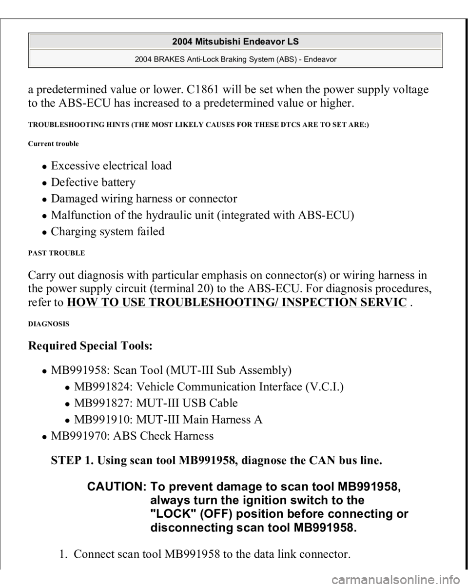
STEP 1. Using scan tool MB991958, diagnose the CAN bus line.
1. Connect scan tool MB991958 to the data link connec
tor. CAUTION: To prevent damage to scan tool MB991958,
always turn the ignition switch to the
"LOCK" (OFF) position before connecting or
disconnecting scan tool MB991958.
2004 Mitsubishi Endeavor LS
2004 BRAKES Anti-Lock Braking System (ABS) - Endeavor
Page 191 of 3870
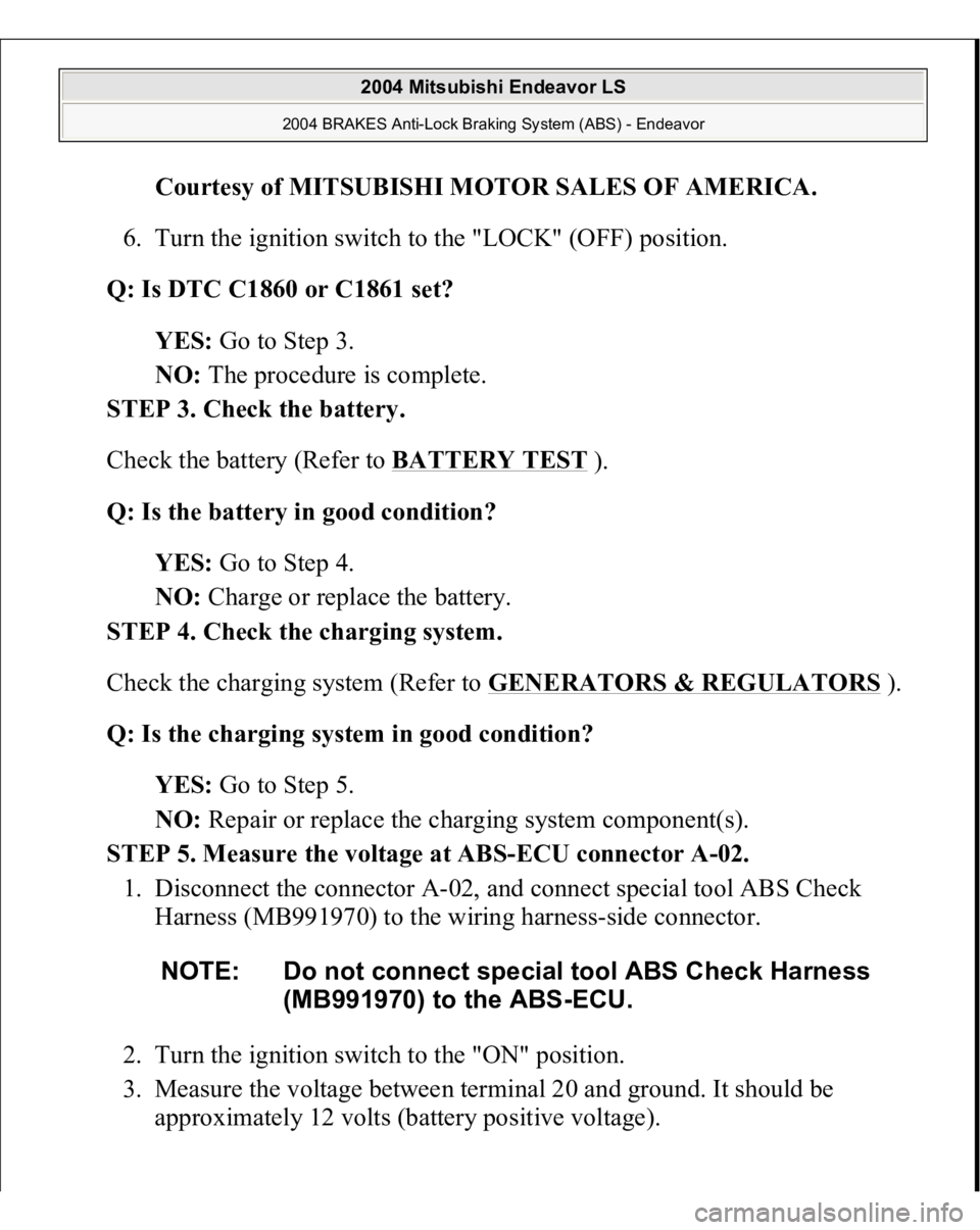
Courtesy of MITSUBISHI MOTOR SALES OF AMERICA
.
6. Turn the ignition switch to the "LOCK" (OFF) position.
Q: Is DTC C1860 or C1861 set?
YES: Go to Step 3.
NO: The procedure is complete.
STEP 3. Check the battery.
Check the battery (Refer to BATTERY TEST
).
Q: Is the battery in good condition?
YES: Go to Step 4.
NO: Charge or replace the battery.
STEP 4. Check the charging system.
Check the charging system (Refer to GENERATORS & REGULATORS
).
Q: Is the charging system in good condition?
YES: Go to Step 5.
NO: Repair or replace the charging system component(s).
STEP 5. Measure the voltage at ABS-ECU connector A-02.
1. Disconnect the connector A-02, and connect special tool ABS Check
Harness (MB991970) to the wiring harness-side connector.
2. Turn the ignition switch to the "ON" position.
3. Measure the voltage between terminal 20 and ground. It should be
approximately 12 volts (battery positive voltage). NOTE: Do not connect special tool ABS Check Harness
(MB991970) to the ABS-ECU.
2004 Mitsubishi Endeavor LS
2004 BRAKES Anti-Lock Braking System (ABS) - Endeavor
Page 217 of 3870
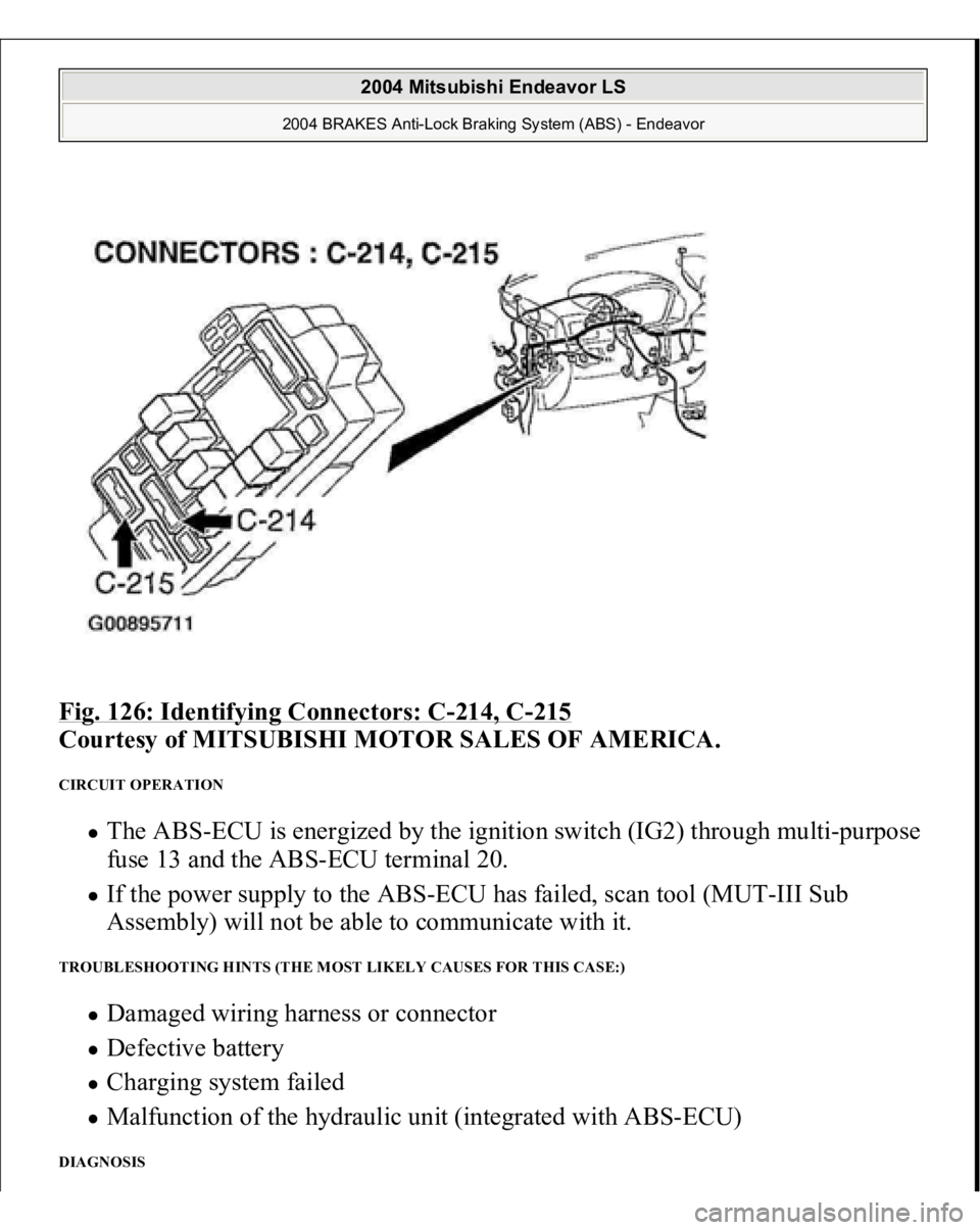
Fig. 126: Identifying Connectors: C
-214, C
-215
Courtesy of MITSUBISHI MOTOR SALES OF AMERICA.
CIRCUIT OPERATION
The ABS-ECU is energized by the ignition switch (IG2) through multi-purpose
fuse 13 and the ABS-ECU terminal 20. If the power supply to the ABS-ECU has failed, scan tool (MUT-III Sub
Assembly) will not be able to communicate with it.
TROUBLESHOOTING HINTS (THE MOST LIKELY CAUSES FOR THIS CASE:)
Damaged wiring harness or connector Defective battery Charging system failed Malfunction of the hydraulic unit (integrated with ABS-ECU)
DIAGNOSIS
2004 Mitsubishi Endeavor LS
2004 BRAKES Anti-Lock Braking System (ABS) - Endeavor
Page 229 of 3870
YES: Repair or replace the damaged components(s). Then go to Step 8 .
NO: An open circuit may be present in the ground circuit. Repair the
wiring harness between ABS-ECU connector A-02 terminals 2, 18 and the
body ground. Then go to Step 8 .
STEP 5. Check the battery.
Check the battery (Refer to BATTERY TEST
).
Q: Is the battery in good condition?
YES: Go to Step 6.
NO: Charge or replace the battery. Then go to Step 8 .
STEP 6. Check the charging system.
Check the charging system (Refer to GENERATORS & REGULATORS
).
Q: Is the charging system in good condition?
YES: Go to Step 7.
NO: Repair or replace the charging system component(s).
Then go to Step 8 .
STEP 7. Retest the system.
Q: Can the ABS-ECU communicate with the scan tool (MUT-III Sub
Assembly)?
YES: It can be assumed that this malfunction is intermittent. Refer to
HOW TO COPE WITH INTERMITTENT MALFUNCTIONS
.
NO: Replace the ABS-ECU. Then go to Step 8.
STEP 8. Retest the system.
Q: Can the ABS-ECU communicate with the scan tool (MUT-III Sub
Assembly)?
2004 Mitsubishi Endeavor LS
2004 BRAKES Anti-Lock Braking System (ABS) - Endeavor
Page 346 of 3870
then retrieve DTCs. If DTC 94 is retrieved, go to step 1 . If DTC 94 is not
retrieved, system is normal at this time. Intermittent condition may exist.
DIAGNOSTIC TESTS (DUAL-STAGE AIR BAG SYSTEM) INSPECTION PROCEDURE 1 Connect scan tool to Data Link Connector (DLC). See INITIAL SRS DIAGNOSTIC PROCEDURE
under DIAGNOSTICS. Turn ignition on. If scan
tool is able to diagnose CAN bus lines and CAN bus lines are satisfactory, inspect
and repair power circuits. Go to INSPECTION PROCEDURE 2
. If scan tool
cannot diagnose CAN bus lines, inspect and repair CAN bus lines.
INSPECTION PROCEDURE 2 1. Connect scan tool to Data Link Connector (DLC). See INITIAL SRS
DIAGNOSTIC PROCEDURE
under DIAGNOSTICS. Disconnect SRS ECU
connector C-26. See SRS ELECTRONIC CONTROL UNIT (SRS ECU)
under REMOVAL & INSTALLATION. See Fig. 30
. Measure resistance
between ground and connector C-26, terminal No. 40 (Black wire). If
resistance is 2 ohms or less, go to next step. If resistance is more than 2 ohms,
repair wiring harness between SRS ECU and ground. See WIRE REPAIR
.
2. Inspect Black/White wire and Black/Yellow wire between connector C-26 and
ignition switch connector C-308, including junction block connectors C-211
and C-215. See Fig. 22
. If wires are okay, go to next step. If wires are not
okay, replace wire harness.
3. Inspect battery. If battery is in good condition, go to next step. If battery is not
in good condition, charge or replace battery as appropriate. Go to step 5 .
4. Inspect charging system. If charging system is okay, go to next step. If
charging system is not okay, repair charging system as appropriate. Go to next
step.
5. Retest SRS system. If scan tool can communicate with SRS ECU, an
intermittent condition may have existed. If scan tool cannot communicate with
NOTE: If scan tool cannot communicate with SRS ECU, CAN bus
line may be defective.
2004 Mitsubishi Endeavor Limited
2004 ACCESSORIES/SAFETY EQUIPMENT Mitsubishi - Air Bag Restraint Systems
Page 697 of 3870
2. Remove the battery from the vehicle.
3. Inspect battery carrier for damage caused by loss of acid from the battery. If
acid damage is present, it is necessary to clean area with a solution of clean
warm water and baking soda. Scrub area with a stiff bristle brush. Wipe clean
with a cloth moistened with ammonia or baking soda in water.
4. Clean the battery, especially the top with same solutions as described in step 3.
5. Inspect the battery case and cover for cracks. If cracks are present, battery must
be replaced.
6. Clean the battery post with a suitable battery post cleaning tool.
7. Clean the inside surfaces of the terminal clamps with a suitable battery
terminal cleaning tool. Replace damaged or frayed cables and broken terminal
clamps.
8. Install the battery in the vehicle.
9. Connect the positive and negative cables to the battery in the order of mention.
10. Tighten the clamp nut securely. BATTERY CHARGING Battery electrolyte temperature may temporarily be allowed to rise to 55°C (131°F).
Increase of electrolyte temperature above 55°C (131°F) is harmful to the battery,
causing deformation of battery cell, decrease in life of battery, etc.
case is cracked or leaking to protect hands from
the electrolyte. A suitable pair of rubber gloves
(not the household type) should be worn when
removing battery by hand.
WARNING:When batteries are being charged, an explosive gas
forms beneath the cover of each cell. Do not smoke
near batteries on charge or which have recently
been charged. Do not break live circuits at the
terminals of the batteries on charge. A spark will
occur where the live circuit is broken. Keep all open
flames away from the battery.
2004 Mitsubishi Endeavor Limited 2004 ELECTRICAL Battery - Endeavor
Page 698 of 3870
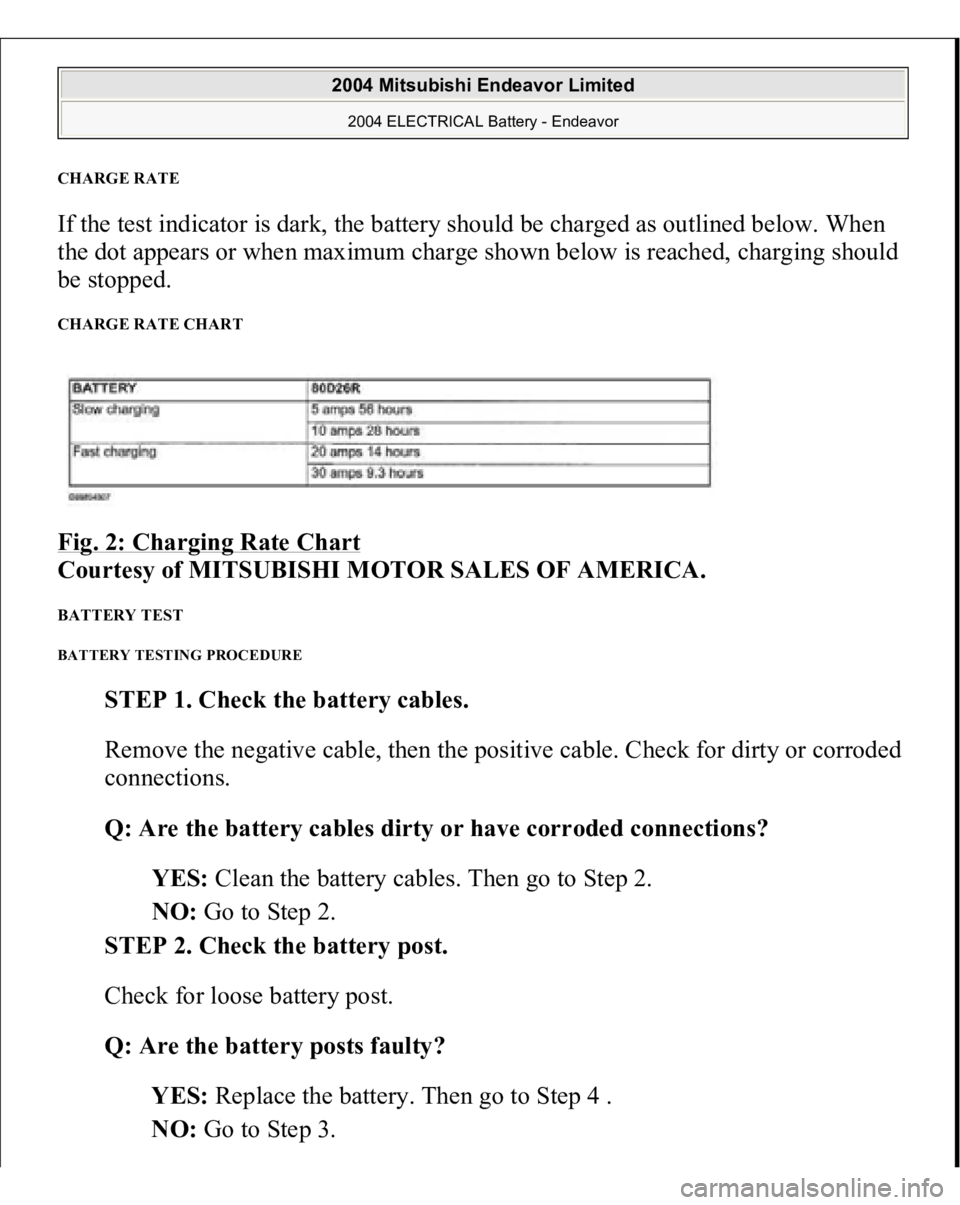
CHARGE RATE If the test indicator is dark, the battery should be charged as outlined below. When
the dot appears or when maximum charge shown below is reached, charging should
be stopped. CHARGE RATE CHART Fig. 2: Charging Rate Chart
Courtesy of MITSUBISHI MOTOR SALES OF AMERICA.
BATTERY TEST BATTERY TESTING PROCEDURE
STEP 1. Check the battery cables.
Remove the negative cable, then the positive cable. Check for dirty or corroded
connections.
Q: Are the battery cables dirty or have corroded connections?
YES: Clean the battery cables. Then go to Step 2.
NO: Go to Step 2.
STEP 2. Check the battery post.
Check for loose battery post.
Q: Are the battery posts faulty?
YES: Replace the battery. Then go to Step 4 .
NO: Go to Step 3.
2004 Mitsubishi Endeavor Limited 2004 ELECTRICAL Battery - Endeavor
Page 1269 of 3870
2004 STARTING & CHARGING SYSTEMS
Generators & Regulators - Endeavor
DESCRIPTION The charging system charges the battery with the generator output to keep the
battery charged at a constant level during varying electrical load. OPERATION Rotation of the excited field coil generates AC voltage in the stator. This alternating
current is rectified through diodes to DC voltage having a waveform. The average
output voltage fluctuates slightly with the generator load condition.
When the ignition switch is turned on, current flows in the field coil and initial
excitation of the field coil occurs. When the stator coil begins to generate power
after the engine is started, the field coil is excited by the output current of the stator
coil. The generator output voltage rises as the field current increases and it falls as
the field current decreases. When the battery positive voltage (generator S terminal
voltage) reaches a regulated voltage of approximately 14.4V, the field current is cut
off. When the battery positive voltage drops below the regulated voltage, the
voltage regulator regulates the output voltage to a constant level by controlling the
field current. In addition, when the field current is constant, the generator output
volta
ge rises as the en
gine s
peed increases. See Fig. 1
or Fig. 2
.
NOTE: See appropriate SELF DIAGNOSTICS article in ENGINE
PERFORMANCE to properly diagnose charging system.
2004 Mitsubishi Endeavor Limited
2004 STARTING & CHARGING SYSTEMS Generators & Regulators - Endeavor
2004 Mitsubishi Endeavor Limited
2004 STARTING & CHARGING SYSTEMS Generators & Regulators - Endeavor