2004 MITSUBISHI ENDEAVOR tires
[x] Cancel search: tiresPage 3 of 3870
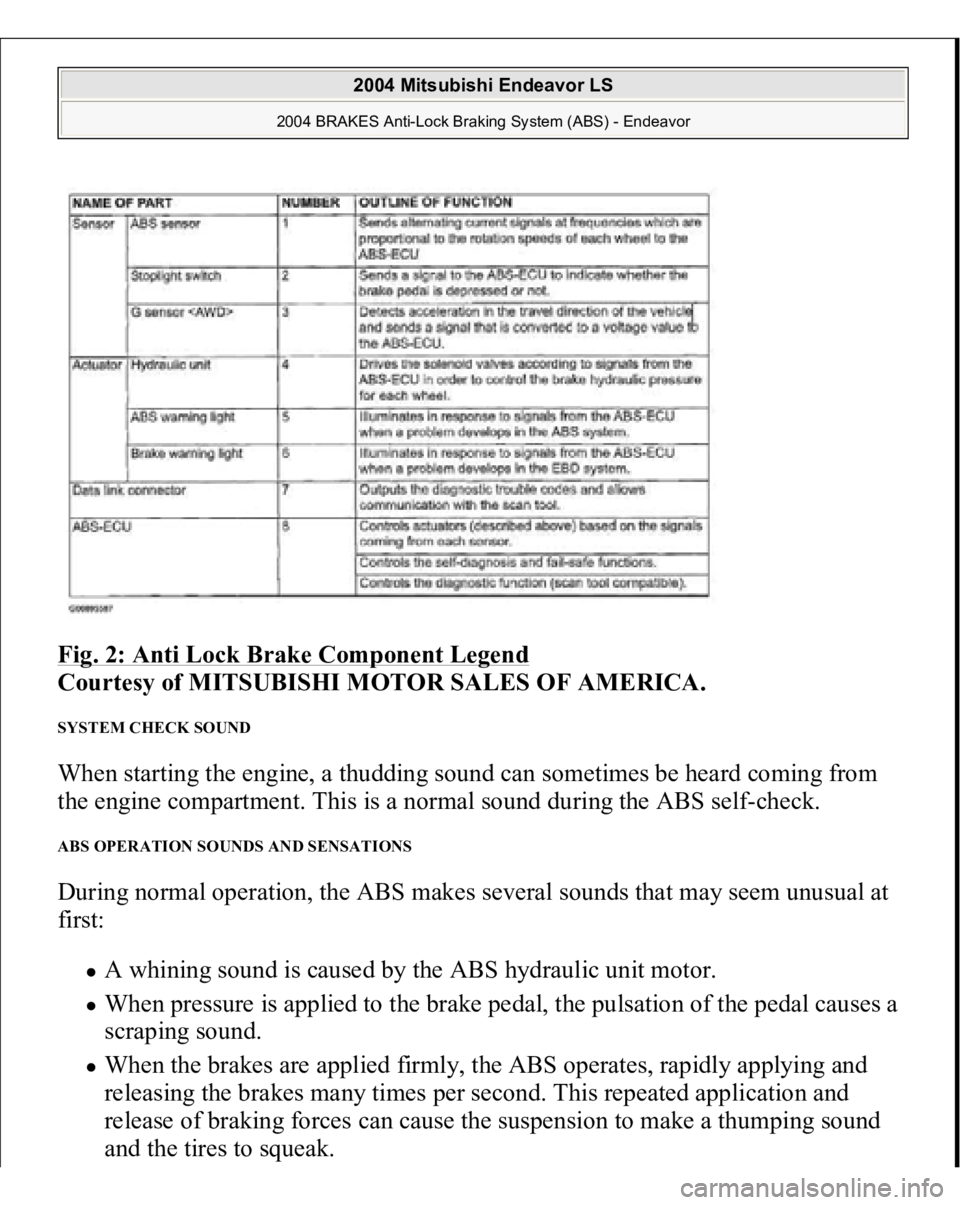
Fig. 2: Anti Lock Brake Component Legend
Courtesy of MITSUBISHI MOTOR SALES OF AMERICA.
SYSTEM CHECK SOUND When starting the engine, a thudding sound can sometimes be heard coming from
the engine compartment. This is a normal sound during the ABS self-check. ABS OPERATION SOUNDS AND SENSATIONS During normal operation, the ABS makes several sounds that may seem unusual at
first:
A whining sound is caused by the ABS hydraulic unit motor. When pressure is applied to the brake pedal, the pulsation of the pedal causes a
scraping sound. When the brakes are applied firmly, the ABS operates, rapidly applying and
releasing the brakes many times per second. This repeated application and
release of braking forces can cause the suspension to make a thumping sound
and the tires to s
queak.
2004 Mitsubishi Endeavor LS
2004 BRAKES Anti-Lock Braking System (ABS) - Endeavor
Page 280 of 3870
leads. Wrap connections with electrical tape.
3. Secure driver-side air bag module to an old tire and wheel. Run harness wires
through hole at rear of air bag module, through hole in wheel and out beneath
tire. Stack 3 more tires on top of first tire. Tie tires together with rope in four
locations. Untwist ends of deployment harness. Connect ends of deployment
harness to terminals of a 12-volt battery to deploy air bag module. If air bag
module fails to deploy, go to step 7 . If air bag module deploys, wait at least 30
minutes for air bag module to cool before touching. Go to next step.
4. Remove remaining components. See
REMOVAL & INSTALLATION
. For
passenger-side air bag modules and seat belt pretensioners, place component
on ground at least 20 feet (6.1 m) away from people or objects. Ensure trim
cover of passenger-side air bag module is facing up. For side impact air bag
modules, position seat back so rear of seat back is in contact with ground
surface, at least 20 feet (6.1 m) away from people or objects.
5. Make a deployment harness using two wires at least 20 feet (6.1 m) in length.
Temporarily twist wires on one end of harness together to prevent unexpected
deployment. Connect wires at other end of harness to stripped wires of SRS
Air Bag Adapter Harness "B" (MB686560) for passenger-side or side impact
air bag modules or SRS Air Bag Adapter Harness (MR991885) for seat belt
pretensioners.
6. Wrap connections with insulating tape. Connect appropriate adapter harness to
component connector. If deploying passenger-side air bag module or seat belt
pretensioner, secure component to a scrap tire and wheel. Run harness wires
through air bag module mounting hole, through hole in wheel and out beneath
tire. Stack 3 more tires on top of first tire. Tie tires together with rope in four
locations.
7. To deploy appropriate component, connect ends of deployment harness to
terminals of a 12-volt battery. If any component fails to deploy, stay away from
component. Contact manufacturer for further instructions. After deployment,
allow at least 30 minutes for component to cool before touching. Tightly seal
deployed component in a strong plastic bag and dispose of it as you would any
other part.
POST
-COLLISION INSPECTION
2004 Mitsubishi Endeavor Limited
2004 ACCESSORIES/SAFETY EQUIPMENT Mitsubishi - Air Bag Restraint Systems
Page 1786 of 3870
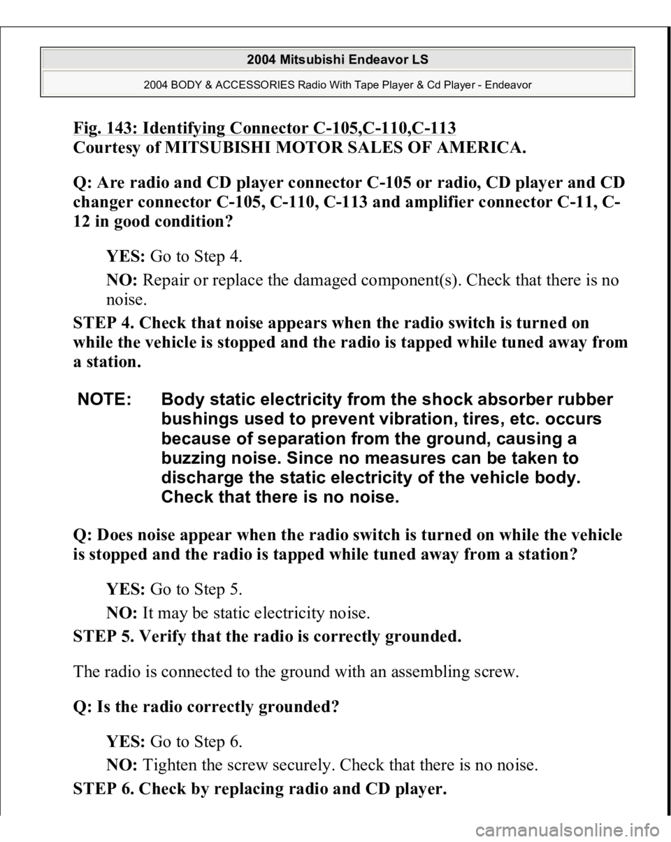
Fig. 143: Identifying Connector C
-105,C
-110,C
-113
Courtesy of MITSUBISHI MOTOR SALES OF AMERICA.
Q: Are radio and CD player connector C-105 or radio, CD player and CD
changer connector C-105, C-110, C-113 and amplifier connector C-11, C-
12 in good condition?
YES: Go to Step 4.
NO: Repair or replace the damaged component(s). Check that there is no
noise.
STEP 4. Check that noise appears when the radio switch is turned on
while the vehicle is sto
pp
ed and the radio is ta
pp
ed while tuned awa
y from
a station.
Q: Does noise appear when the radio switch is turned on while the vehicle
is stopped and the radio is tapped while tuned away from a station?
YES: Go to Step 5.
NO: It may be static electricity noise.
STEP 5. Verify that the radio is correctly grounded.
The radio is connected to the ground with an assembling screw.
Q: Is the radio correctly grounded?
YES: Go to Step 6.
NO: Tighten the screw securely. Check that there is no noise.
STEP 6. Check by replacing radio and CD player.
NOTE: Body static electricity from the shock absorber rubber
bushings used to prevent vibration, tires, etc. occurs
because of separation from the ground, causing a
buzzing noise. Since no measures can be taken to
discharge the static electricity of the vehicle body.
Check that there is no noise.
2004 Mitsubishi Endeavor LS
2004 BODY & ACCESSORIES Radio With Tape Player & Cd Player - Endeavor
Page 1788 of 3870
Q: Is the problem station or location specific?
YES: The effect of an electrical field condition (multipath noise, fading
noise) could be the cause. Check that there is not noise.
NO: Go to Step 4.
STEP 4. Check that noise appears when the radio switch is turned on
while the vehicle is stopped.
Q: Does noise appear when the radio switch is turned on while the vehicle
is stopped and the radio is tapped while tuned away from a station?
YES: Go to Step 5.
NO: It may be static electricity noise.
STEP 5. Verify that the radio is correctly grounded.
The radio is connected to the ground with an assembling screw.
Q: Is the radio correctly grounded?
YES: Go to Step 6.
NO: Tighten the screw securely. Check that there is no noise.
Fading noise
This is a buzzing noise that occurs when the
broadcast signal is disrupted by obstructing
objects and the signal strength fluctuates intricately
within a narrow range.
NOTE: Body static electricity from the shock absorber rubber
bushings used to prevent vibration, tires, etc. occurs
because of separation from the ground, causing a
buzzing noise. There is no measures to discharge the
static electricity of the vehicle body. Check that there is
no noise.
2004 Mitsubishi Endeavor LS
2004 BODY & ACCESSORIES Radio With Tape Player & Cd Player - Endeavor
Page 1939 of 3870
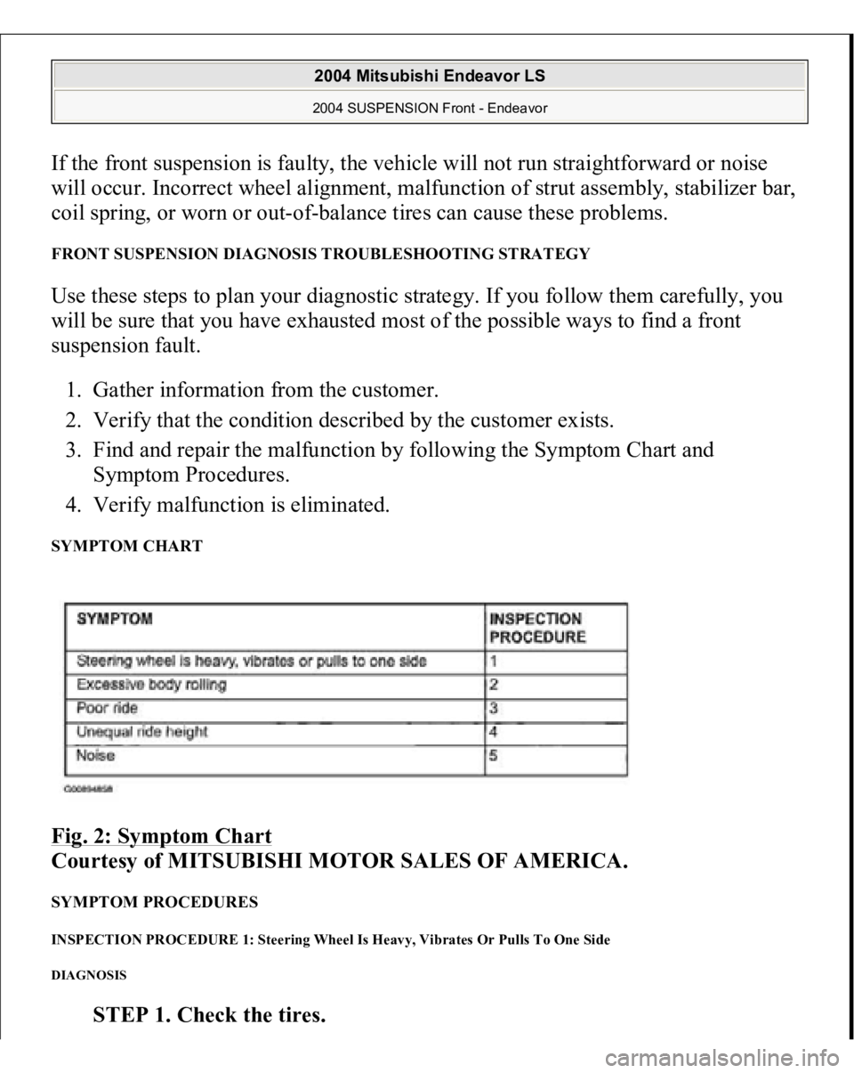
If the front suspension is faulty, the vehicle will not run straightforward or noise
will occur. Incorrect wheel alignment, malfunction of strut assembly, stabilizer bar,
coil spring, or worn or out-of-balance tires can cause these problems. FRONT SUSPENSION DIAGNOSIS TROUBLESHOOTING STRATEGY Use these steps to plan your diagnostic strategy. If you follow them carefully, you
will be sure that you have exhausted most of the possible ways to find a front
suspension fault.
1. Gather information from the customer.
2. Verify that the condition described by the customer exists.
3. Find and repair the malfunction by following the Symptom Chart and
Symptom Procedures.
4. Verify malfunction is eliminated. SYMPTOM CHART Fig. 2: Symptom Chart
Courtesy of MITSUBISHI MOTOR SALES OF AMERICA.
SYMPTOM PROCEDURES INSPECTION PROCEDURE 1: Steering Wheel Is Heavy, Vibrates Or Pulls To One Side DIAGNOSIS
STEP 1. Check the tires.
2004 Mitsubishi Endeavor LS 2004 SUSPENSION Front - Endeavor
Page 1940 of 3870
Q: Are the tires in normal condition?
YES: Go to Step 2.
NO: If out of balance, balance the tires as necessary. If excessively worn,
replace the tires as necessary and go to Step 5 .
STEP 2. Check the wheel alignment.
Refer to ON
-VEHICLE SERVICE
.
Q: Is the wheel alignment correct?
YES: Go to Step 3.
NO: Adjust it, then go to Step 5 .
STEP 3. Check the lower arm ball joint.
Q: Is the ball joint in good condition?
YES: Go to Step 4.
NO: Replace the lower arm assembly, then go to Step 5 .
STEP 4. Check the coil spring.
Q: Is the coil spring in good condition?
YES: Go to Step 5.
NO: Replace it, then go to Step 5.
STEP 5. Retest the system.
Q: Is the malfunction eliminated?
YES: The procedure is complete.
NO: Return to Step 1 .
INSPECTION PROCEDURE 2: Excessive Body Rolling DIAGNOSIS
STEP 1. Check for broken or deteriorated stabilizer bar
.
2004 Mitsubishi Endeavor LS 2004 SUSPENSION Front - Endeavor
Page 1945 of 3870
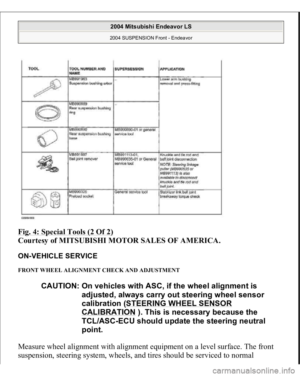
Fig. 4: Special Tools (2 Of 2)
Courtesy of MITSUBISHI MOTOR SALES OF AMERICA.
ON-VEHICLE SERVICE FRONT WHEEL ALIGNMENT CHECK AND ADJUSTMENT Measure wheel alignment with alignment equipment on a level surface. The front
sus
pension, steerin
g system, wheels, and tires should be serviced to normal
CAUTION: On vehicles with ASC, if the wheel alignment is
adjusted, always carry out steering wheel sensor
calibration (STEERING WHEEL SENSOR
CALIBRATION
). This is necessary because the
TCL/ASC-ECU should update the steering neutral
point.
2004 Mitsubishi Endeavor LS 2004 SUSPENSION Front - Endeavor
Page 2834 of 3870
NO: The procedure is complete.
INSPECTION PROCEDURE 9: VIBRATION DIAGNOSIS
STEP 1. Check the tires for out-of-balance.
Q: Is the check result OK?
YES: Go to Step 2.
NO: Balance the tires (Refer to WHEEL BALANCE ACCURACY
).
Then go to Step 4 .
STEP 2. Check the fluid level.
1. Park the vehicle on a flat, level surface, and then start the engine.
2. Turn the steering wheel several times to raise the temperature of the fluid
to approximately 50 - 60°C (122 - 140°F).
3. With the engine running, turn the wheel all the way to the left and right
several times.
4. Check the fluid in the oil reservoir for foaming or milkiness. Check the
difference of the fluid level when the engine is stopped, and while it is
running.
Q: Is the check result OK?
YES: Go to Step 3.
NO: Bleed the air (Refer to POWER STEERING SYSTEM AIR
BLEEDING
). Then go to Step 4 .
NOTE: A slight vibration may be felt when the stationary steering
effort is made due to the condition of the road surface. To
check whether the vibration actually exists or not, test-drive
the vehicle on a dry concrete or asphalt surface. A very
slight amount of vibration is not a malfunction.
2004 Mitsubishi Endeavor LS
2004 STEERING Power Steering - Endeavor