Page 1045 of 3870
Courtesy of MITSUBISHI MOTOR SALES OF AMERICA
.
>>B<< LOWER SASH INSTALLATION Securely insert the lower sash into the window rear sash. INSPECTION FRONT DOOR LATCH CHECK The illustration shows when the door lock actuator is viewed from inside the door. DOOR LOCK ACTUATOR INCORPORATED IN DOOR LATCH CHECK < LEFT SIDE> FRONT DOOR LATCH CHECK SPECIFICATION LEVER POSITION
BATTERY
CONNECTION
LEVER OPERATION
At the "UNLOCK"
position
Connect terminal No.
4 and the negative
battery terminal. Connect terminal No.
6 and the positive
battery terminal.
The lever moves from
the "UNLOCK" position
to the "LOCK" position.
At the "LOCK" position
Connect terminal No.
6 and the negative
battery terminal. Connect terminal No.
4 and the positive
battery terminal.
The lever moves from
the "LOCK" position to
the "UNLOCK"
position.
2004 Mitsubishi Endeavor LS
2004 BODY & ACCESSORIES Door - Endeavor
Page 1048 of 3870
REAR DOOR LOCK ACTUATOR CHECK The illustration shows when the door lock actuator is viewed from outside the door. DOOR LOCK ACTUATOR INCORPORATED IN DOOR LATCH CHECK < LEFT SIDE> DOOR LOCK ACTUATOR LATCH CHECK At the "UNLOCK"
position
2-3
Less than 2 ohms
LEVER POSITION
BATTERY
CONNECTION
LEVER OPERATION
At the "LOCK" position
Connect terminal No.
4 and the negative
battery terminal. Connect terminal No.
6 and the positive
battery terminal.
The lever moves from
the "LOCK" position to
the "UNLOCK"
position.
At the "UNLOCK"
position
Connect terminal No.
6 and the negative
battery terminal. Connect terminal No.
4 and the positive
battery terminal.
The lever moves from
the "UNLOCK" position
to the "LOCK" position.
2004 Mitsubishi Endeavor LS
2004 BODY & ACCESSORIES Door - Endeavor
Page 1050 of 3870
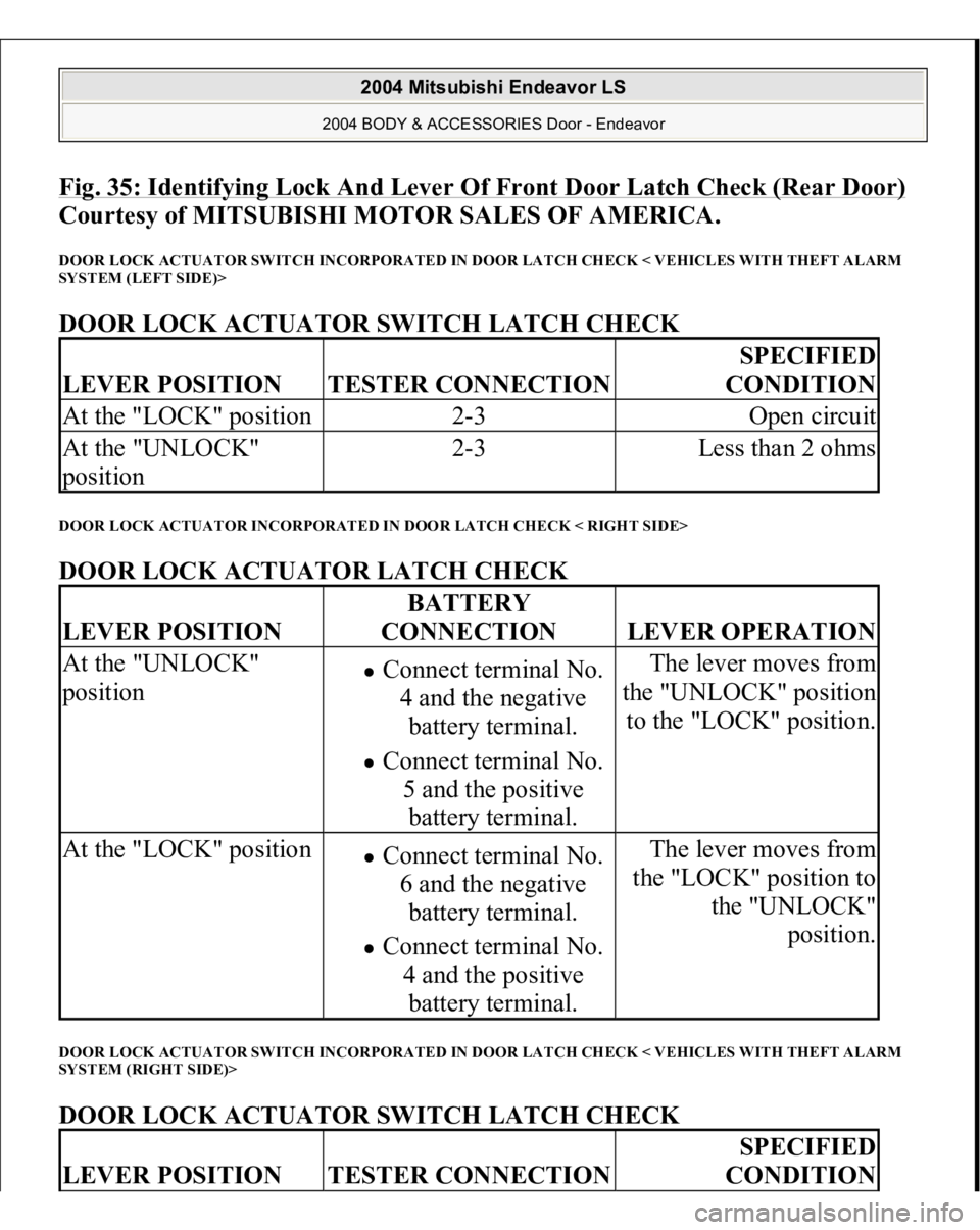
Fig. 35: Identifying Lock And Lever Of Front Door Latch Check (Rear Door)
Courtesy of MITSUBISHI MOTOR SALES OF AMERICA.
DOOR LOCK ACTUATOR SWITCH INCORPORATED IN DOOR LATCH CHECK < VEHICLES WITH THEFT ALARM
SYSTEM (LEFT SIDE)> DOOR LOCK ACTUATOR SWITCH LATCH CHECK DOOR LOCK ACTUATOR INCORPORATED IN DOOR LATCH CHECK < RIGHT SIDE> DOOR LOCK ACTUATOR LATCH CHECK DOOR LOCK ACTUATOR SWITCH INCORPORATED IN DOOR LATCH CHECK < VEHICLES WITH THEFT ALARM
SYSTEM (RIGHT SIDE)> DOOR LOCK ACTUATOR SWITCH LATCH CHECK LEVER POSITION
TESTER CONNECTION
SPECIFIED
CONDITION
At the "LOCK" position
2-3
Open circuit
At the "UNLOCK"
position
2-3
Less than 2 ohms
LEVER POSITION
BATTERY
CONNECTION
LEVER OPERATION
At the "UNLOCK"
position
Connect terminal No.
4 and the negative
battery terminal. Connect terminal No.
5 and the positive
battery terminal.
The lever moves from
the "UNLOCK" position
to the "LOCK" position.
At the "LOCK" position
Connect terminal No.
6 and the negative
battery terminal. Connect terminal No.
4 and the positive
battery terminal.
The lever moves from
the "LOCK" position to
the "UNLOCK"
position.
LEVER POSITION
TESTER CONNECTION
SPECIFIED
CONDITION
2004 Mitsubishi Endeavor LS
2004 BODY & ACCESSORIES Door - Endeavor
Page 1059 of 3870
Fig. 43: Locating Double
-Sided Tape Position (Rear Door)
Courtesy of MITSUBISHI MOTOR SALES OF AMERICA.
INSTALLATION SERVICE POINTS >>A<< WEATHER PROOF FILM INSTALLATION Install the weather
proof film in the order shown.
2004 Mitsubishi Endeavor LS
2004 BODY & ACCESSORIES Door - Endeavor
Page 1068 of 3870
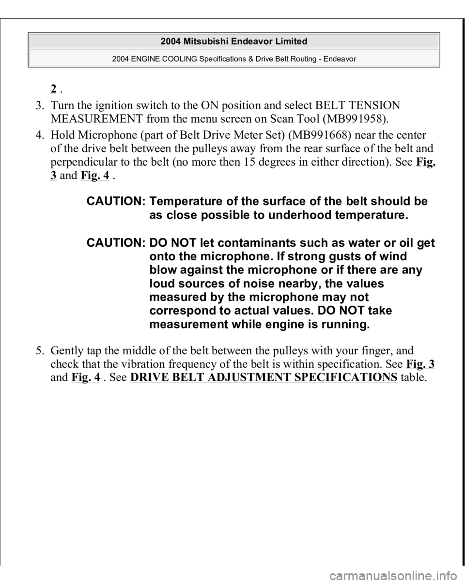
2 .
3. Turn the ignition switch to the ON position and select BELT TENSION
MEASUREMENT from the menu screen on Scan Tool (MB991958).
4. Hold Microphone (part of Belt Drive Meter Set) (MB991668) near the center
of the drive belt between the pulleys away from the rear surface of the belt and
perpendicular to the belt (no more then 15 degrees in either direction). See Fi
g.
3 and Fig. 4
.
5. Gently tap the middle of the belt between the pulleys with your finger, and
check that the vibration frequency of the belt is within specification. See Fig. 3
and Fig. 4
. See DRIVE BELT ADJUSTMENT SPECIFICATIONS
table.
CAUTION: Temperature of the surface of the belt should be
as close possible to underhood temperature.
CAUTION: DO NOT let contaminants such as water or oil get
onto the microphone. If strong gusts of wind
blow against the microphone or if there are any
loud sources of noise nearby, the values
measured by the microphone may not
correspond to actual values. DO NOT take
measurement while engine is running.
2004 Mitsubishi Endeavor Limited
2004 ENGINE COOLING Specifications & Drive Belt Routing - Endeavor
Page 1093 of 3870
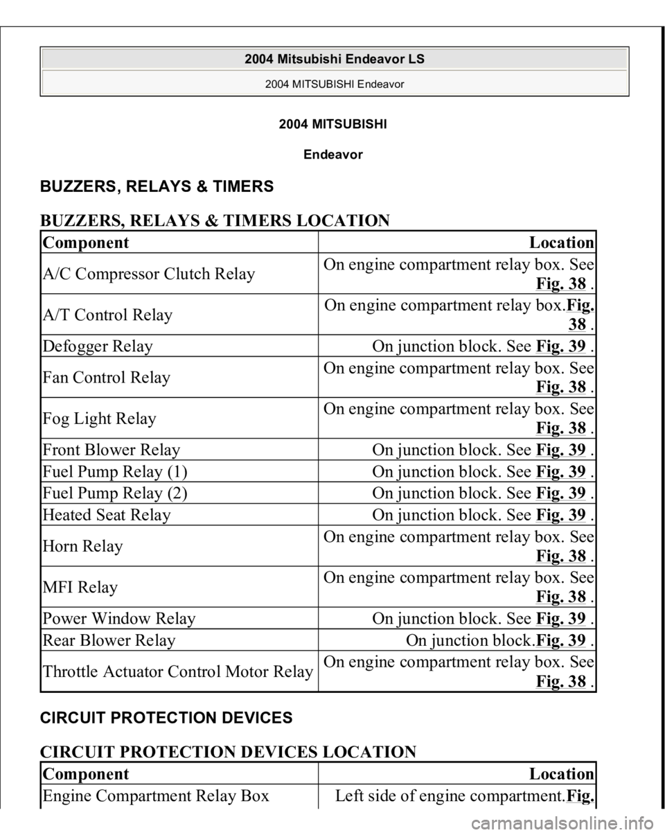
2004 MITSUBISH
I
Endeavor
BUZZERS, RELAYS & TIMERS BUZZERS, RELAYS & TIMERS LOCATION CIRCUIT PROTECTION DEVICES CIRCUIT PROTECTION DEVICES LOCATION Component
Location
A/C Compressor Clutch Relay
On engine compartment relay box. See
Fig. 38
.
A/T Control Relay
On engine compartment relay box.Fig.
38 .
Defogger Relay
On junction block. See Fig. 39
.
Fan Control Relay
On engine compartment relay box. See
Fig. 38
.
Fog Light Relay
On engine compartment relay box. See
Fig. 38
.
Front Blower Relay
On junction block. See Fig. 39
.
Fuel Pump Relay (1)
On junction block. See Fig. 39
.
Fuel Pump Relay (2)
On junction block. See Fig. 39
.
Heated Seat Relay
On junction block. See Fig. 39
.
Horn Relay
On engine compartment relay box. See
Fig. 38
.
MFI Relay
On engine compartment relay box. See
Fig. 38
.
Power Window Relay
On junction block. See Fig. 39
.
Rear Blower Relay
On junction block.Fig. 39
.
Throttle Actuator Control Motor Relay
On engine compartment relay box. See
Fig. 38
.
Component
Location
Engine Compartment Relay Box
Left side of engine compartment.Fi
g.
2004 Mitsubishi Endeavor LS
2004 MITSUBISHI Endeavor
2004 Mitsubishi Endeavor LS
2004 MITSUBISHI Endeavor
Page 1094 of 3870
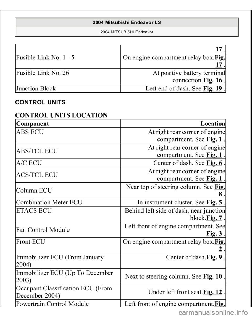
CONTROL UNITS CONTROL UNITS LOCATION
17 .
Fusible Link No. 1 - 5
On engine compartment relay box.Fi
g.
17 .
Fusible Link No. 26
At positive battery terminal
connection.Fig. 16
.
Junction Block
Left end of dash. See Fig. 19
.
Component
Location
ABS ECU
At right rear corner of engine
compartment. See Fig. 1
.
ABS/TCL ECU
At right rear corner of engine
compartment. See Fig. 1
.
A/C ECU
Center of dash. See Fig. 6
.
ACS/TCL ECU
At right rear corner of engine
compartment. See Fig. 1
.
Column ECU
Near top of steering column. See Fi
g. 8 .
Combination Meter ECU
In instrument cluster. See Fig. 5
.
ETACS ECU
Behind left side of dash, near junction
block.Fig. 7
.
Fan Control Module
Left front of engine compartment. See
Fig. 3
.
Front ECU
On engine compartment relay box.Fi
g. 2 .
Immobilizer ECU (From January
2004)
Center of dash.Fig. 9
.
Immobilizer ECU (Up To December
2003)
Next to steering column. See Fig. 10
.
Occupant Classification ECU (From
December 2004)
Under left front seat.Fig. 12
.
Powertrain Control Modul
e
Left front of en
gine com
partment.Fi
g.
2004 Mitsubishi Endeavor LS
2004 MITSUBISHI Endeavor
Page 1095 of 3870
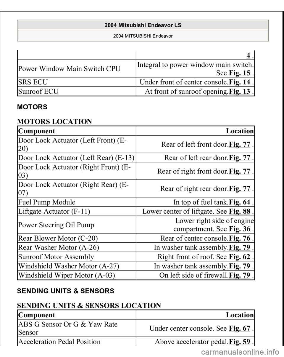
MOTORS MOTORS LOCATION SENDING UNITS & SENSORS SENDING UNITS & SENSORS LOCATION
4 .
Power Window Main Switch CPU
Integral to power window main switch.
See Fig. 15
.
SRS ECU
Under front of center console.Fig. 14
.
Sunroof ECU
At front of sunroof opening.Fig. 13
.
Component
Location
Door Lock Actuator (Left Front) (E-
20)
Rear of left front door.Fig. 77
.
Door Lock Actuator (Left Rear) (E-13)
Rear of left rear door.Fig. 77
.
Door Lock Actuator (Right Front) (E-
03)
Rear of right front door.Fig. 77
.
Door Lock Actuator (Right Rear) (E-
07)
Rear of right rear door.Fig. 77
.
Fuel Pump Module
In top of fuel tank.Fig. 64
.
Liftgate Actuator (F-11)
Lower center of liftgate. See Fig. 88
.
Power Steering Oil Pump
Lower right side of engine
compartment. See Fig. 36
.
Rear Blower Motor (C-20)
Rear of center console.Fig. 76
.
Rear Washer Motor (A-26)
In washer tank assembly.Fig. 79
.
Sunroof Motor Assembly
Right front of roof. See Fig. 62
.
Windshield Washer Motor (A-27)
In washer tank assembly.Fig. 79
.
Windshield Wiper Motor (A-03)
On left side of firewall.Fig. 79
.
Component
Location
ABS G Sensor Or G & Yaw Rate
Sensor
Under center console. See Fig. 67
.
Acceleration Pedal Position
Above accelerator pedal.Fig. 59
.
2004 Mitsubishi Endeavor LS
2004 MITSUBISHI Endeavor