2004 MITSUBISHI ENDEAVOR USB port
[x] Cancel search: USB portPage 21 of 3870

The amount of voltage generated at each wheel is determined by the clearance
between the ABS rotor teeth and the ABS sensor, and by the speed of rotation. Sends alternating current signals at frequencies which are proportional to the
rotation speeds of each wheel to the ABS electronic control unit (ABS-ECU). The ABS hydraulic unit modulates the amount of braking force individually
applied to each wheel cylinder.
ABS DTC SET CONDITIONS The ABS-ECU monitors voltage fluctuation in each ABS sensor circuit. If the ECU
detects short or open circuit in the circuit, it will set a diagnostic trouble code. TROUBLESHOOTING HINTS (THE MOST LIKELY CAUSES FOR THESE DTCS ARE TO SET ARE:)
Current trouble
Malfunction of the ABS sensor Damaged wiring harness or connector Malfunction of the hydraulic unit (integrated with ABS-ECU)
Past trouble
Carry out diagnosis with particular emphasis o connector(s) or wiring harness
in ABS sensor circuit. For diagnosis procedures, refer to HOW TO USE TROUBLESHOOTING/ INSPECTION SERVIC
).
DIAGNOSIS Required Special Tools:
MB991958: Scan Tool (MUT-III Sub Assembly)
MB991824: Vehicle Communication Interface (V.C.I.) MB991827: MUT-III USB Cable MB991910: MUT-III Main Harness A
MB991970: ABS Check Harness
STEP 1. Using scan tool MB991958, diagnose the CAN bus line.
2004 Mitsubishi Endeavor LS
2004 BRAKES Anti-Lock Braking System (ABS) - Endeavor
Page 253 of 3870
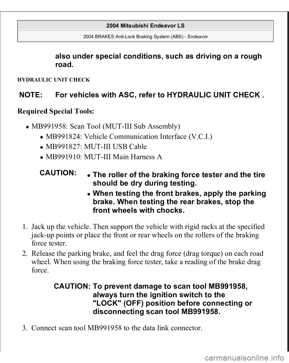
HYDRAULIC UNIT CHECK Required Special Tools:
MB991958: Scan Tool (MUT-III Sub Assembly)
MB991824: Vehicle Communication Interface (V.C.I.) MB991827: MUT-III USB Cable MB991910: MUT-III Main Harness A
1. Jack up the vehicle. Then support the vehicle with rigid racks at the specified
jack-up points or place the front or rear wheels on the rollers of the braking
force tester.
2. Release the parking brake, and feel the drag force (drag torque) on each road
wheel. When using the braking force tester, take a reading of the brake drag
force.
3. Connect scan tool MB991958 to the data link connec
tor. also under special conditions, such as driving on a rough
road.
NOTE: For vehicles with ASC, refer to HYDRAULIC UNIT CHECK
.
CAUTION:
The roller of the braking force tester and the tire
should be dry during testing. When testing the front brakes, apply the parking
brake. When testing the rear brakes, stop the
front wheels with chocks.
CAUTION: To prevent damage to scan tool MB991958,
always turn the ignition switch to the
"LOCK" (OFF) position before connecting or
disconnecting scan tool MB991958.
2004 Mitsubishi Endeavor LS
2004 BRAKES Anti-Lock Braking System (ABS) - Endeavor
Page 1521 of 3870
Courtesy of MITSUBISHI MOTOR SALES OF AMERICA
.
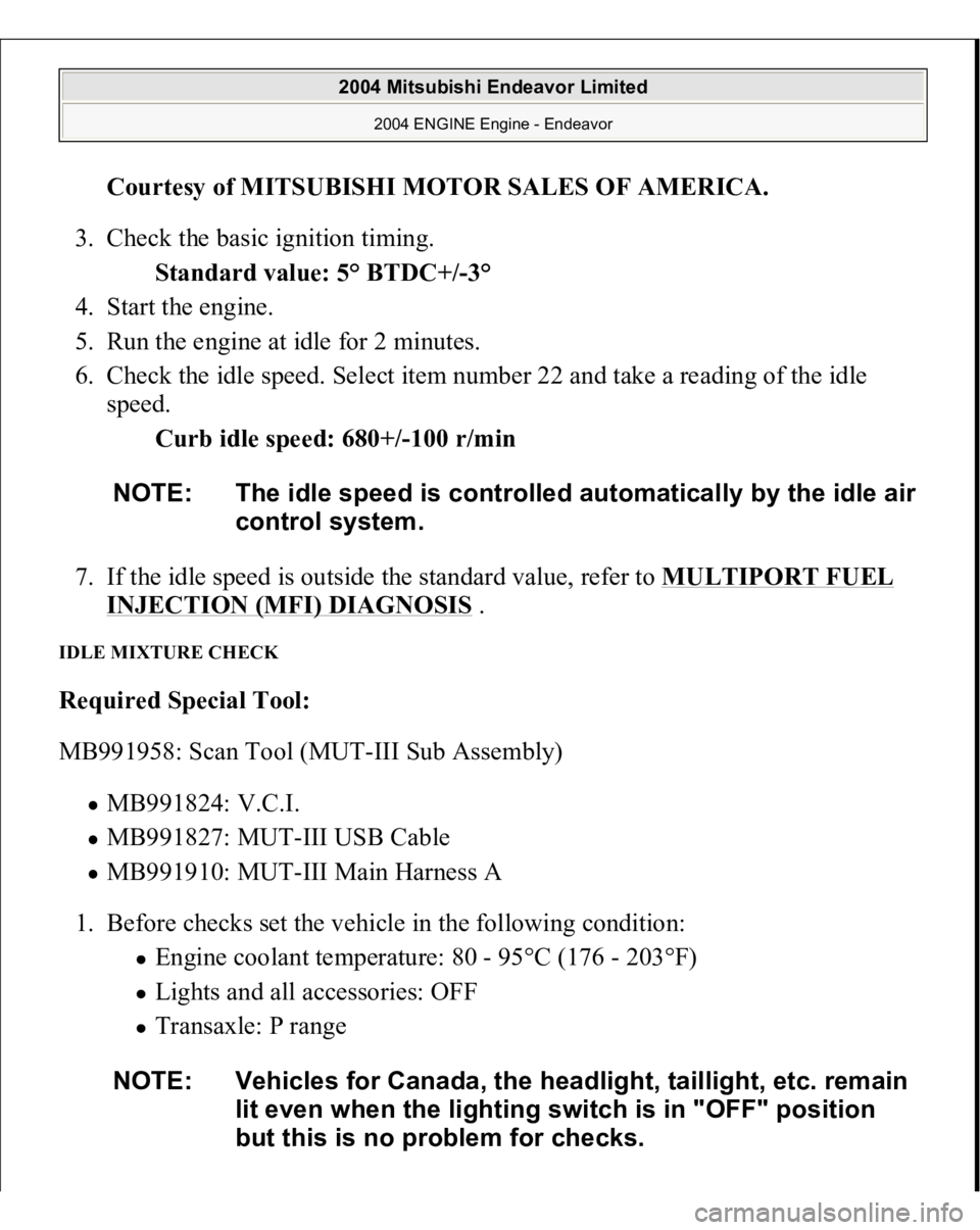
3. Check the basic ignition timing.
Standard value: 5° BTDC+/-3°
4. Start the engine.
5. Run the engine at idle for 2 minutes.
6. Check the idle speed. Select item number 22 and take a reading of the idle
speed.
Curb idle speed: 680+/-100 r/min
7. If the idle speed is outside the standard value, refer to MULTIPORT FUEL
INJECTION (MFI) DIAGNOSIS
.
IDLE MIXTURE CHECK Required Special Tool:
MB991958: Scan Tool (MUT-III Sub Assembly)
MB991824: V.C.I. MB991827: MUT-III USB Cable MB991910: MUT-III Main Harness A
1. Before checks set the vehicle in the following condition:
Engine coolant temperature: 80 - 95°C (176 - 203°F) Lights and all accessories: OFF Transaxle: P range
NOTE: The idle speed is controlled automaticall
y by the idle air
control system.
NOTE: Vehicles for Canada, the headlight, taillight, etc. remain
lit even when the lighting switch is in "OFF" position
but this is no problem for checks.
2004 Mitsubishi Endeavor Limited
2004 ENGINE Engine - Endeavor
Page 2002 of 3870
INTRODUCTION TO HEATER, AIR CONDITIONING AND VENTILATION DIAGNOSISAir is drawn into the heater assembly from either the outside, or from the inside of
the passenger cabin if DEFROST, maximum cooling or RECIRCULATION are
selected. The air is then forced through the evaporator where heat is removed,
cooling and de-humidifying the air. Depending on the temperature selected, a
portion of this air is then forced through the heater core to achieve the selected
discharge temperature.
If the system does not cool properly, look for a problem with the refrigerant, blower
or air distribution systems. If the system does not heat properly, look for a problem
with the coolant, blower or air distribution systems. In either case all system fuses,
circuit breaker and relays should be checked. HEATER, AIR CONDITIONING AND VENTILATION DIAGNOSTIC TROUBLESHOOTING
STRATEGY Use these steps to plan your diagnostic strategy. If you follow them carefully, you
will be sure that you have exhausted most of the possible ways to find a heater, air
conditioning and ventilation fault.
1. Gather information from the customer.
2. Verify that the condition described by the customer exists.
3. Find the malfunction by following
SYMPTOM CHART
4. Verify that the malfunction is eliminated.
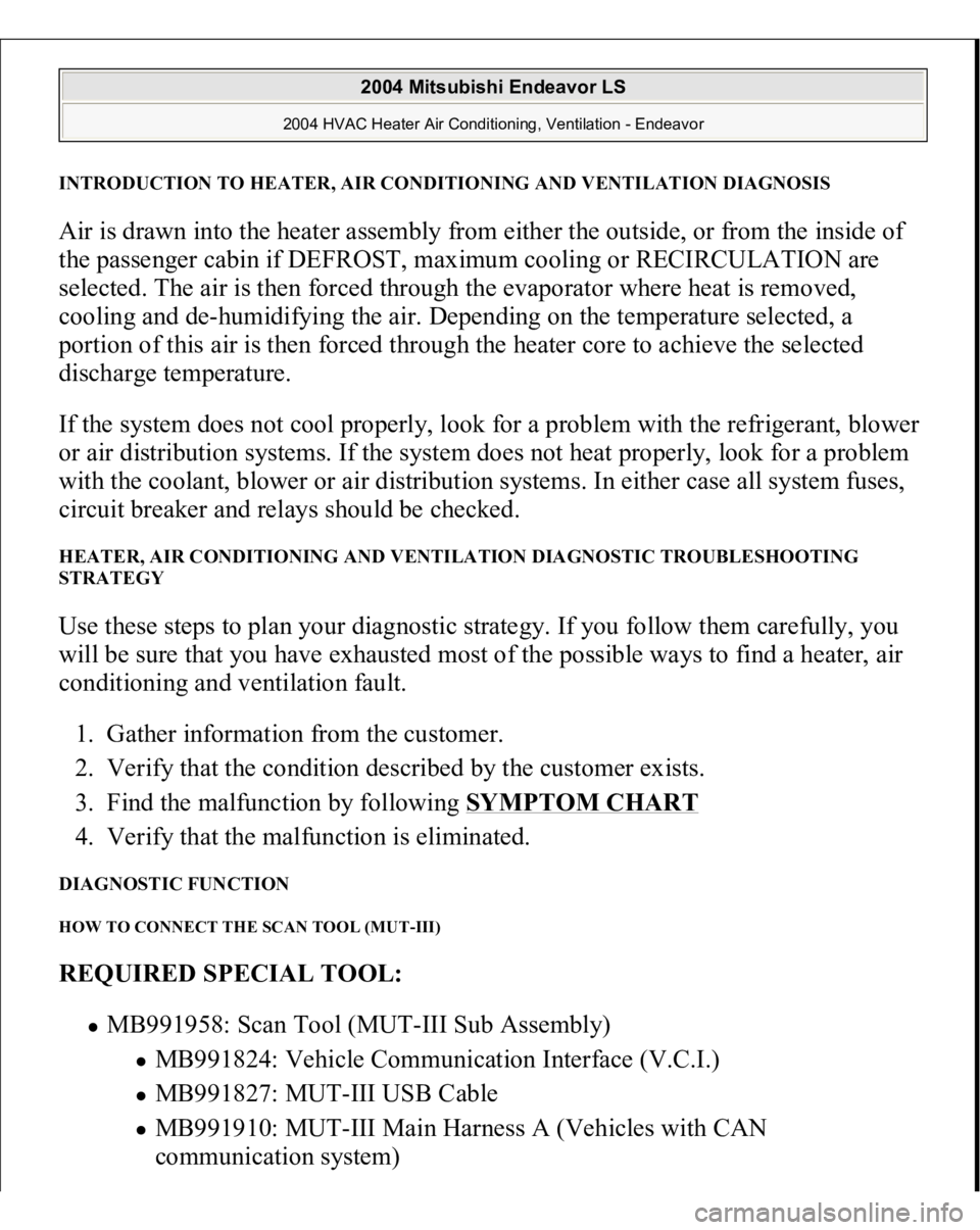
DIAGNOSTIC FUNCTION HOW TO CONNECT THE SCAN TOOL (MUT-III) REQUIRED SPECIAL TOOL:
MB991958: Scan Tool (MUT-III Sub Assembly)
MB991824: Vehicle Communication Interface (V.C.I.) MB991827: MUT-III USB Cable MB991910: MUT-III Main Harness A (Vehicles with CAN
communication system)
2004 Mitsubishi Endeavor LS
2004 HVAC Heater Air Conditioning, Ventilation - Endeavor
Page 3156 of 3870
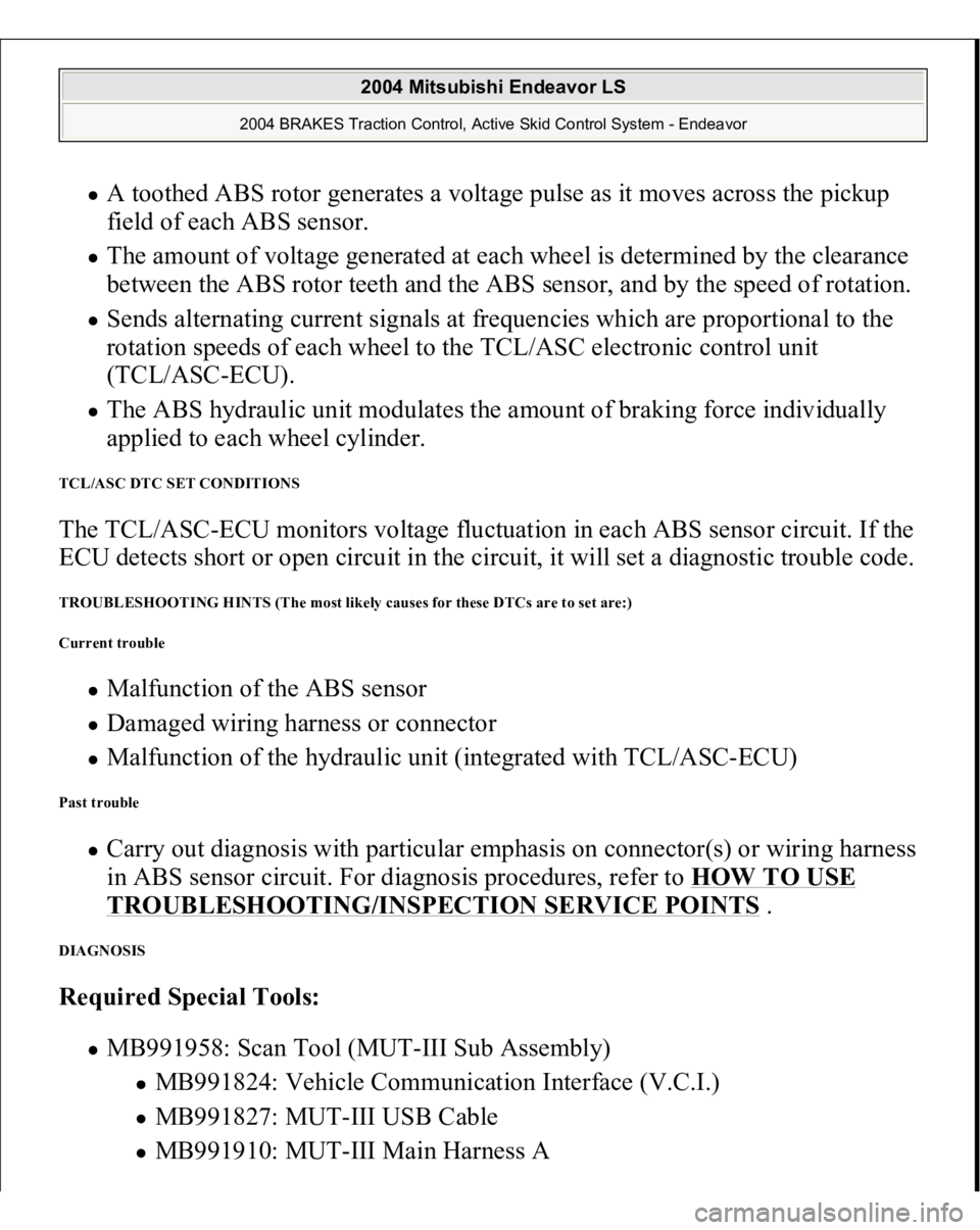
A toothed ABS rotor generates a voltage pulse as it moves across the pickup
field of each ABS sensor. The amount of voltage generated at each wheel is determined by the clearance
between the ABS rotor teeth and the ABS sensor, and by the speed of rotation. Sends alternating current signals at frequencies which are proportional to the
rotation speeds of each wheel to the TCL/ASC electronic control unit
(TCL/ASC-ECU). The ABS hydraulic unit modulates the amount of braking force individually
applied to each wheel cylinder.
TCL/ASC DTC SET CONDITIONS The TCL/ASC-ECU monitors voltage fluctuation in each ABS sensor circuit. If the
ECU detects short or open circuit in the circuit, it will set a diagnostic trouble code. TROUBLESHOOTING HINTS (The most likely causes for these DTCs are to set are:)
Current trouble
Malfunction of the ABS sensor Damaged wiring harness or connector Malfunction of the hydraulic unit (integrated with TCL/ASC-ECU)
Past trouble
Carry out diagnosis with particular emphasis on connector(s) or wiring harness
in ABS sensor circuit. For diagnosis procedures, refer to HOW TO USE TROUBLESHOOTING/INSPECTION SERVICE POINTS
.
DIAGNOSIS Required Special Tools:
MB991958: Scan Tool (MUT-III Sub Assembly)
MB991824: Vehicle Communication Interface (V.C.I.) MB991827: MUT-III USB Cable MB991910: MUT-III Main Harness A
2004 Mitsubishi Endeavor LS
2004 BRAKES Traction Control, Active Skid Control System - Endeavor
Page 3196 of 3870
between the ABS rotor teeth and the ABS sensor, and by the speed of rotation. Sends alternating current signals at frequencies which are proportional to the
rotation speeds of each wheel to the TCL/ASC electronic control unit
(TCL/ASC-ECU). The ABS hydraulic unit modulates the amount of braking force individually
applied to each wheel cylinder.
ABS DTC SET CONDITIONS The TCL/ASC-ECU monitors the signals from each ABS sensor while the vehicle
is being driven. If any faults below are found in these sensor signals, the ECU will
set the relevant diagnostic trouble code.
Missing sensor signal Sensor signal, which will not be created under normal operation Significant difference among the ABS sensor signals
TROUBLESHOOTING HINTS (The most likely causes for these DTCs are to set are:)
Current trouble
Malfunction of the ABS sensor or ABS rotor Damaged wiring harness or connector Malfunction of the hydraulic unit (integrated with TCL/ASC-ECU)
Past trouble
Carry out diagnosis with particular emphasis on connector(s) or wiring harness
in ABS sensor circuit. For diagnosis procedures, refer to "HOW TO USE TROUBLESHOOTING/INSPECTION SERVICE POINTS
.
DIAGNOSIS Required Special Tools:
MB991958: Scan Tool (MUT-III Sub Assembly)
MB991824: Vehicle Communication Interface (V.C.I.) MB991827: MUT-III USB Cable
2004 Mitsubishi Endeavor LS
2004 BRAKES Traction Control, Active Skid Control System - Endeavor