2004 MITSUBISHI ENDEAVOR ad blue
[x] Cancel search: ad bluePage 309 of 3870
DIAGNOSTIC TESTS INSPECTION PROCEDURE 1 No communication between scan tool and all systems is most likely in power
supply or ground circuits to Data Link Connector (DLC). Check wire harness and
connectors for damage and loose connections. See WIRING DIAGRAMS
.
INSPECTION PROCEDURE 2 1. Before proceeding, see AIR BAG SAFETY PRECAUTIONS
. Disconnect
SRS ECU connector C-26. See SRS ELECTRONIC CONTROL UNIT
(SRS ECU)
under REMOVAL & INSTALLATION. See Fig. 19
. Measure
resistance between SRS ECU connector C-26, terminal No. 20 (Orange/Blue
wire) and Data Link Connector (DLC), terminal No. 7 (Orange/Blue wire). See
Fig. 20
& Fig. 21
. If resistance is more than 2 ohms, go to next step. If
resistance is 2 ohms or less, go to step 4 .
2. Measure resistance between SRS ECU connector C-26, terminal No. 15 (Black
wire) and ground. If resistance is less than 2 ohms, go to next step. If resistance
is 2 ohms or more, go to step 5 .
3. Connect negative battery cable. Turn ignition on. Measure voltage between
ground and SRS ECU connector C-26, terminals No. 13 (Black/White wire)
and No. 16 (Black/Yellow wire). If voltage is less than 9 volts at either
terminal, go to step 6 . If voltage at both terminals is 9 volts or more, recheck
trouble s
ymptom. If s
ymptom still exists, re
place SRS ECU. Go to ste
p 7 .
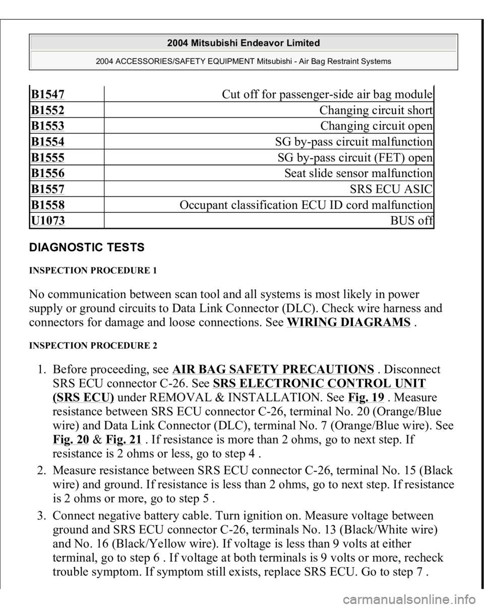
B1547
Cut off for passenger-side air bag module
B1552
Changing circuit short
B1553
Changing circuit open
B1554
SG by-pass circuit malfunction
B1555
SG by-pass circuit (FET) open
B1556
Seat slide sensor malfunction
B1557
SRS ECU ASIC
B1558
Occupant classification ECU ID cord malfunction
U1073
BUS of
f
2004 Mitsubishi Endeavor Limited
2004 ACCESSORIES/SAFETY EQUIPMENT Mitsubishi - Air Bag Restraint Systems
Page 310 of 3870
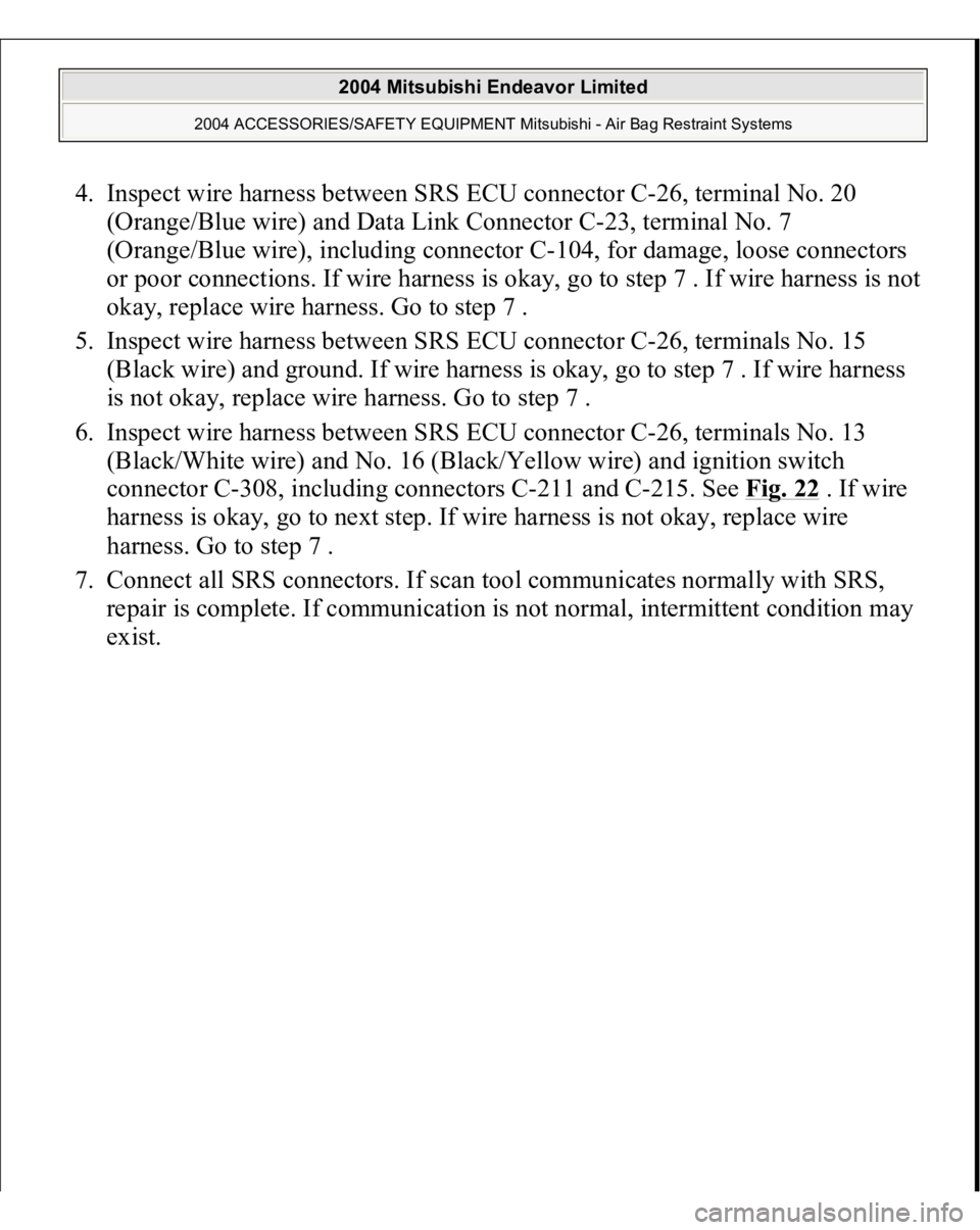
4. Inspect wire harness between SRS ECU connector C-26, terminal No. 20
(Orange/Blue wire) and Data Link Connector C-23, terminal No. 7
(Orange/Blue wire), including connector C-104, for damage, loose connectors
or poor connections. If wire harness is okay, go to step 7 . If wire harness is not
okay, replace wire harness. Go to step 7 .
5. Inspect wire harness between SRS ECU connector C-26, terminals No. 15
(Black wire) and ground. If wire harness is okay, go to step 7 . If wire harness
is not okay, replace wire harness. Go to step 7 .
6. Inspect wire harness between SRS ECU connector C-26, terminals No. 13
(Black/White wire) and No. 16 (Black/Yellow wire) and ignition switch
connector C-308, including connectors C-211 and C-215. See Fig. 22
. If wire
harness is okay, go to next step. If wire harness is not okay, replace wire
harness. Go to step 7 .
7. Connect all SRS connectors. If scan tool communicates normally with SRS,
repair is complete. If communication is not normal, intermittent condition may
exist.
2004 Mitsubishi Endeavor Limited
2004 ACCESSORIES/SAFETY EQUIPMENT Mitsubishi - Air Bag Restraint Systems
Page 313 of 3870
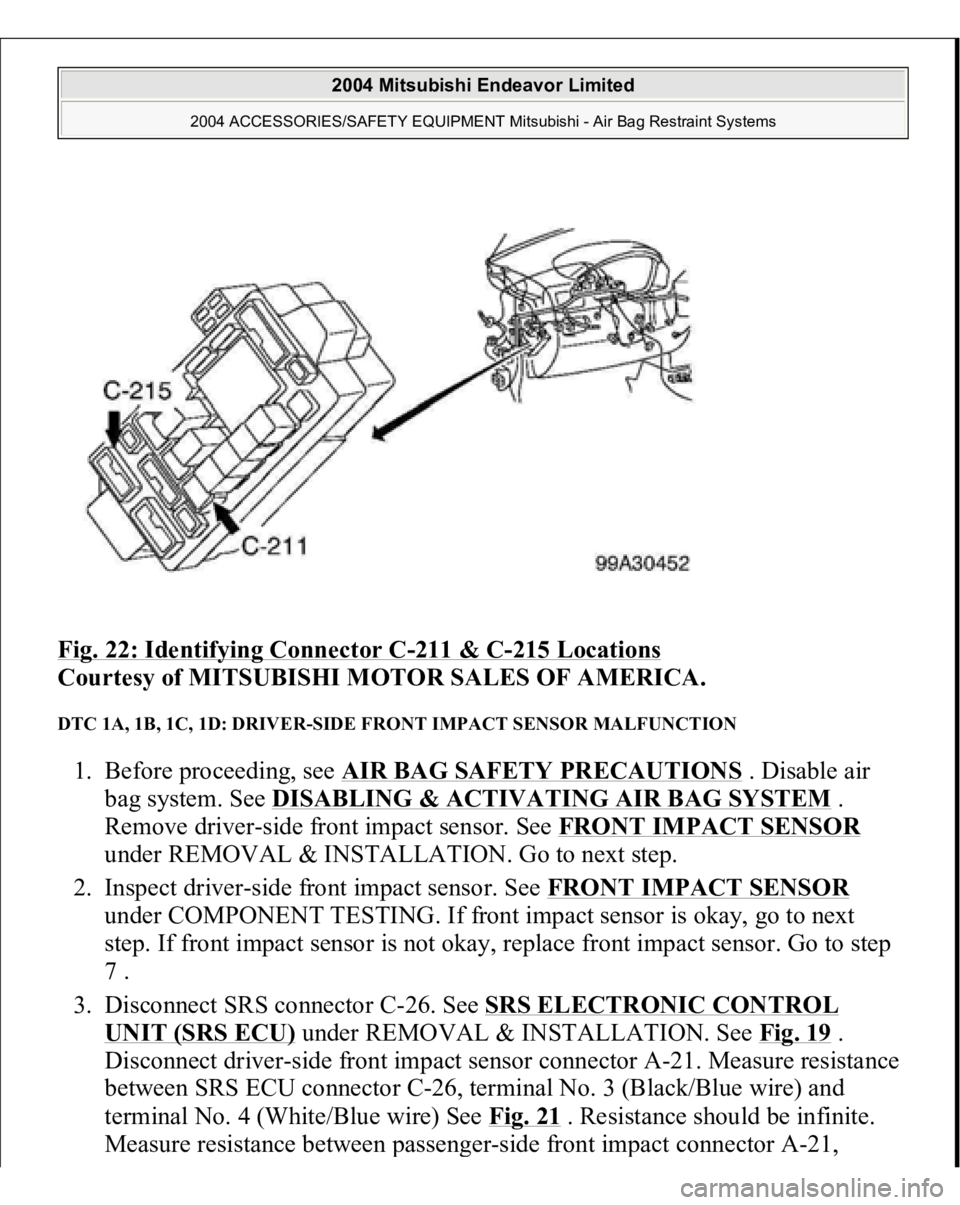
Fig. 22: Identifying Connector C
-211 & C
-215 Locations
Courtesy of MITSUBISHI MOTOR SALES OF AMERICA.
DTC 1A, 1B, 1C, 1D: DRIVER-SIDE FRONT IMPACT SENSOR MALFUNCTION 1. Before proceeding, see AIR BAG SAFETY PRECAUTIONS
. Disable air
bag system. See DISABLING & ACTIVATING AIR BAG SYSTEM
.
Remove driver-side front impact sensor. See FRONT IMPACT SENSOR
under REMOVAL & INSTALLATION. Go to next step.
2. Inspect driver-side front impact sensor. See FRONT IMPACT SENSOR
under COMPONENT TESTING. If front impact sensor is okay, go to next
step. If front impact sensor is not okay, replace front impact sensor. Go to step
7 .
3. Disconnect SRS connector C-26. See SRS ELECTRONIC CONTROL
UNIT (SRS ECU)
under REMOVAL & INSTALLATION. See Fig. 19
.
Disconnect driver-side front impact sensor connector A-21. Measure resistance
between SRS ECU connector C-26, terminal No. 3 (Black/Blue wire) and
terminal No. 4 (White/Blue wire) See Fig. 21
. Resistance should be infinite.
Measure resistance between
passen
ger-side front im
pact connector
A-21,
2004 Mitsubishi Endeavor Limited
2004 ACCESSORIES/SAFETY EQUIPMENT Mitsubishi - Air Bag Restraint Systems
Page 316 of 3870
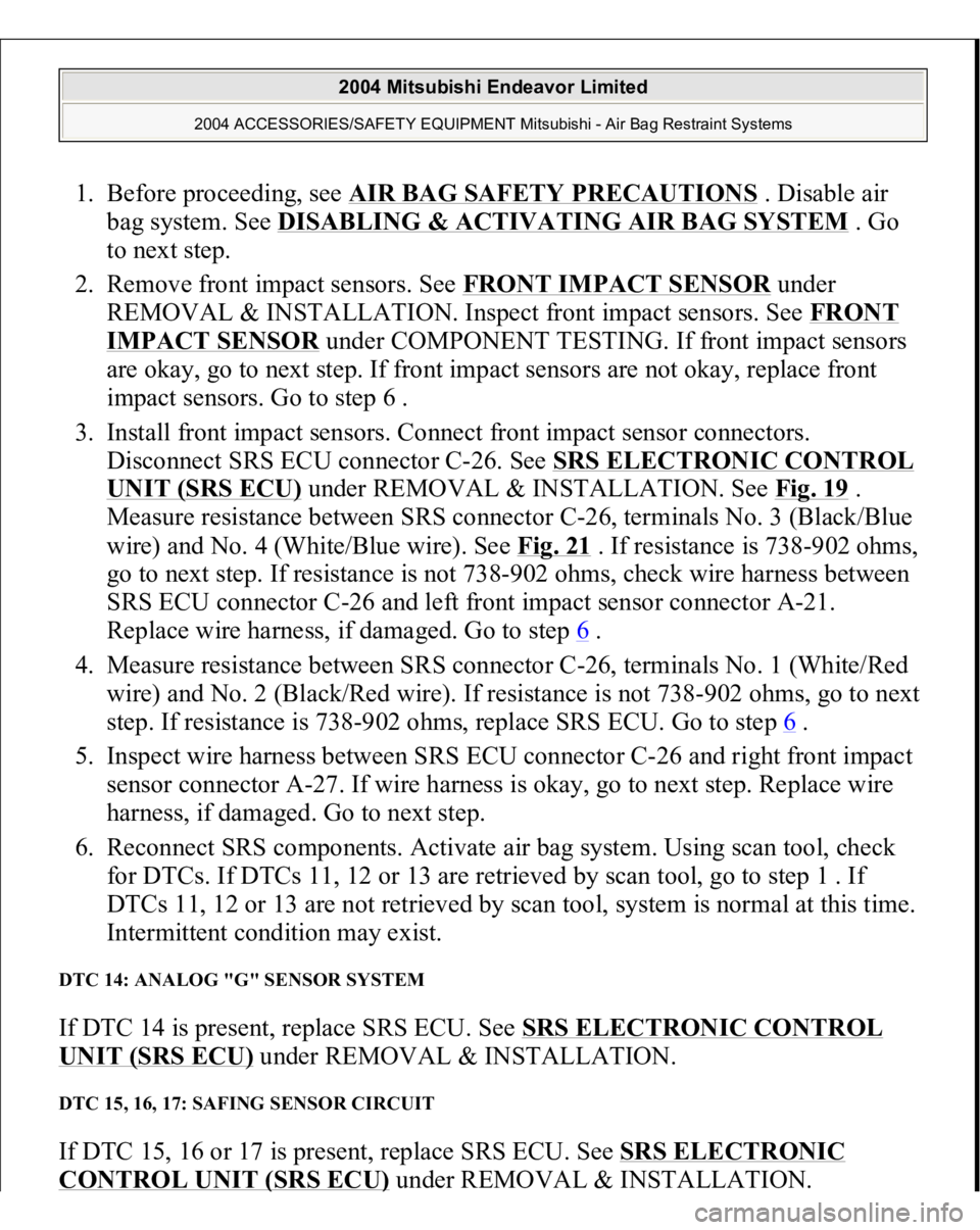
1. Before proceeding, see AIR BAG SAFETY PRECAUTIONS
. Disable air
bag system. See DISABLING & ACTIVATING AIR BAG SYSTEM
. Go
to next step.
2. Remove front impact sensors. See FRONT IMPACT SENSOR
under
REMOVAL & INSTALLATION. Inspect front impact sensors. See FRONT
IMPACT SENSOR
under COMPONENT TESTING. If front impact sensors
are okay, go to next step. If front impact sensors are not okay, replace front
impact sensors. Go to step 6 .
3. Install front impact sensors. Connect front impact sensor connectors.
Disconnect SRS ECU connector C-26. See SRS ELECTRONIC CONTROL
UNIT (SRS ECU)
under REMOVAL & INSTALLATION. See Fig. 19
.
Measure resistance between SRS connector C-26, terminals No. 3 (Black/Blue
wire) and No. 4 (White/Blue wire). See Fig. 21
. If resistance is 738-902 ohms,
go to next step. If resistance is not 738-902 ohms, check wire harness between
SRS ECU connector C-26 and left front impact sensor connector A-21.
Replace wire harness, if damaged. Go to step 6 .
4. Measure resistance between SRS connector C-26, terminals No. 1 (White/Red
wire) and No. 2 (Black/Red wire). If resistance is not 738-902 ohms, go to next
step. If resistance is 738-902 ohms, replace SRS ECU. Go to step 6
.
5. Inspect wire harness between SRS ECU connector C-26 and right front impact
sensor connector A-27. If wire harness is okay, go to next step. Replace wire
harness, if damaged. Go to next step.
6. Reconnect SRS components. Activate air bag system. Using scan tool, check
for DTCs. If DTCs 11, 12 or 13 are retrieved by scan tool, go to step 1 . If
DTCs 11, 12 or 13 are not retrieved by scan tool, system is normal at this time.
Intermittent condition may exist.
DTC 14: ANALOG "G" SENSOR SYSTEM If DTC 14 is present, replace SRS ECU. See SRS ELECTRONIC CONTROL UNIT (SRS ECU)
under REMOVAL & INSTALLATION.
DTC 15, 16, 17: SAFING SENSOR CIRCUIT If DTC 15, 16 or 17 is present, replace SRS ECU. See SRS ELECTRONIC CONTROL UNIT
(SRS ECU
)under REMOVAL & INSTALLATION.
2004 Mitsubishi Endeavor Limited
2004 ACCESSORIES/SAFETY EQUIPMENT Mitsubishi - Air Bag Restraint Systems
Page 321 of 3870
ohms in each wire, go to next step. If resistance is more than 2 ohms in either
wire, replace wire harness. Go to next step.
4. Reconnect all SRS components. Activate air bag system. Using scan tool, erase
then retrieve DTCs. If DTC 25 is retrieved, go to step 1 . If DTC 25 is not
retrieved, system is normal at this time. Intermittent condition may exist.
DTC 26: DRIVER-SIDE SEAT BELT PRETENSIONER SHORT CIRCUIT 1. Before proceeding, see AIR BAG SAFETY PRECAUTIONS
. Disable SRS.
See DISABLING & ACTIVATING AIR BAG SYSTEM
. If DTC 34 is
retrieved, go to next step. If DTC 34 is not retrieved, go to step 3 .
2. Inspect SRS ECU connector C-25. See SRS ELECTRONIC CONTROL
UNIT (SRS ECU)
under REMOVAL & INSTALLATION. See Fig. 19
. If
connector is connected properly, go to next step. If connector is not connected
properly, connect properly and go to step 7 .
3. Disconnect negative battery cable. Disconnect, then reconnect SRS ECU
connector C-25 and driver-side seat belt pretensioner connector D-24. See
SEAT BELT PRETENSIONER
under REMOVAL & INSTALLATION.
Connect negative battery cable. Using scan tool, check for DTCs. If DTC 26 is
retrieved, go to next step. If DTC 26 is not retrieved, system is normal at this
time.
4. Disconnect negative battery cable. Connect Load Resistor (MB991865) to
Resistor Harness (MB991884). Connect resistor harness to driver-side seat belt
pretensioner connector D-24. Connect negative battery cable. Using scan tool,
check for DTCs. If DTC 26 is retrieved, go to next step. If DTC 26 is not
retrieved, replace driver-side seat belt pretensioner.
5. Disconnect SRS ECU connector C-25 and driver-side seat belt connector D-24.
Insert a cable tie or similar insulator between terminals No. 29 (Red/Blue wire)
and No. 30 (Red/Yellow wire) of SRS ECU connector to release shorting bar.
See Fig. 21
. If continuity exists between terminals No. 29 and 30, go to next
ste
p. If continuit
y does not exist, between terminals No. 29 and 30, erase, then
NOTE: Ensure shorting bar in SRS ECU connector is released by
using a cable tie or similar non conducting item to release
shorting bar before performing electrical measurements.
2004 Mitsubishi Endeavor Limited
2004 ACCESSORIES/SAFETY EQUIPMENT Mitsubishi - Air Bag Restraint Systems
Page 323 of 3870
2. Disconnect driver-side seat belt pretensioner connector D-24. See SEAT
BELT PRETENSIONER
under REMOVAL & INSTALLATION. See Fig.
19 . Connect Load Resistor (MB991865) to Resistor Harness (MB991884).
Connect resistor harness to driver-side seat belt pretensioner connector.
Connect negative battery cable. Using scan tool, check for DTCs. If DTC 27 is
retrieved, go to next step. If DTC 27 is not retrieved, replace driver-side seat
belt pretensioner.
3. Disconnect SRS ECU connector C-25. See SRS ELECTRONIC CONTROL UNIT (SRS ECU)
under REMOVAL & INSTALLATION. Measure
resistance of Red/Blue wire between SRS ECU connector C-25, terminal No.
29 and driver-side seat belt pretensioner connector D-26, terminal No. 1. See
Fig. 21
& Fig. 25
. Measure resistance of Red/Yellow wire between SRS ECU
connector terminal No. 30 and driver-side seat belt pretensioner connector D-
26, terminal No. 2. If resistance is 2 ohms or less in both wires, erase, then
retrieve DTCs using scan tool. If DTC 27 is retrieved, replace SRS ECU. Go to
next step. If resistance is more than 2 ohms in either wire, replace wire harness
between SRS ECU and seat belt pretensioner. Go to next step.
4. Reconnect all SRS components. Activate air bag system. Using scan tool, erase
then retrieve DTCs. If DTC 27 is retrieved, go to step 1 . If DTC 27 is not
retrieved, system is normal at this time. Intermittent condition may exist.
DTC 28: PASSENGER-SIDE SEAT BELT PRETENSIONER SHORT CIRCUIT 1. Before proceeding, see AIR BAG SAFETY PRECAUTIONS
. Disable SRS.
See DISABLING & ACTIVATING AIR BAG SYSTEM
. If DTC 34 is
retrieved, go to next step. If DTC 34 is not retrieved, go to step 3 .
2. Inspect SRS ECU connector C-25. See SRS ELECTRONIC CONTROL
UNIT (SRS ECU)
under REMOVAL & INSTALLATION. See Fig. 19
. If
connector is connected properly, go to next step. If connector is not connected
properly, connect properly. Go to step 7 .
3. Disconnect ne
gative batter
y cable. Disconnect SRS ECU connector
C-25 and
NOTE: Ensure shorting bar in SRS ECU connector is released by
using a cable tie or similar non conducting item to release
shorting bar before performing electrical measurements.
2004 Mitsubishi Endeavor Limited
2004 ACCESSORIES/SAFETY EQUIPMENT Mitsubishi - Air Bag Restraint Systems
Page 334 of 3870
3. Reconnect all SRS components. Activate air bag system. Using scan tool, erase
then retrieve DTCs. If DTC 65 is retrieved, go to step 1 . If DTC 65 is not
retrieved, system is normal at this time. Intermittent condition may exist. DTC 66: DRIVER-SIDE SEAT BELT PRETENSIONER SHORT TO VOLTAGE 1. Before proceeding, see AIR BAG SAFETY PRECAUTIONS
. Disable air
bag system. See DISABLING & ACTIVATING AIR BAG SYSTEM
. Go
to next step.
2. Disconnect driver-side seat belt pretensioner connector D-24. See SEAT
BELT PRETENSIONER
under REMOVAL & INSTALLATION. See Fig.
19 . Connect Load Resistor (MB991865) to Load Resistor Harness
(MB991884). Connect load resistor harness to connector D-24. Connect
negative battery cable. Using scan tool, erase then retrieve DTCs. If DTC 66 is
retrieved, go to next step. If DTC 66 is not retrieved, replace driver-side seat
belt pretensioner. Go to step 4 .
3. Turn ignition off. Disconnect SRS ECU connector C-25. See SRS ELECTRONIC CONTROL UNIT (SRS ECU)
under REMOVAL &
INSTALLATION. Remove load resistor harness from driver-side seat belt
pretensioner connector D-24. Turn ignition on. Measure voltage between
ground and SRS ECU connector C-25, terminal No. 29 (Red/Blue wire) and
No. 30 (Red/Yellow wire). If voltage is measured at either terminal, replace
wire harness between SRS ECU and seat belt pretensioner. Go to next step. If
voltage is not measured at either terminal, reconnect SRS components. Using
scan tool, erase then retrieve DTCs. If DTC 66 is retrieved, replace SRS ECU.
Go to next step.
4. Reconnect all SRS components. Using scan tool, check for DTCs. If DTC 66 is
retrieved, go to step 1 . If DTC 66 is not retrieved, system is normal at this
time. Intermittent condition may exist.
DTC 67: DRIVER-SIDE SEAT BELT PRETENSIONER SHORT TO GROUND 1. Before proceeding, see AIR BAG SAFETY PRECAUTIONS
. Disable air
bag system. See DISABLING & ACTIVATING AIR BAG SYSTEM
. Go
to next step.
2. Disconnect drive
r-side seat belt
pretensioner connector D-24. See SEAT
2004 Mitsubishi Endeavor Limited
2004 ACCESSORIES/SAFETY EQUIPMENT Mitsubishi - Air Bag Restraint Systems
Page 335 of 3870
BELT PRETENSIONE
R under REMOVAL & INSTALLATION. See Fig.
18 . Connect Load Resistor (MB991866) to Load Resistor Harness
(MB991884). Connect Load Resistor Harness to connector D-24. Connect
negative battery cable. Using scan tool, erase then retrieve DTCs. If DTC 67 is
retrieved, go to next step. If DTC 67 is not retrieved, replace driver-side seat
belt pretensioner. Go to step 4 .
3. Disconnect SRS ECU connector C-25. See SRS ELECTRONIC CONTROL UNIT (SRS ECU)
under REMOVAL & INSTALLATION. Remove load
resistor harness from driver-side seat belt pretensioner connector D-24.
Measure continuity between ground and SRS ECU connector C-25, terminal
No. 29 (Red/Blue wire) and No. 30 (Red/Yellow wire). If continuity is not
found in either circuit, erase then retrieve DTCs. If DTC 67 is retrieved,
replace SRS ECU. Go to next step. If continuity is found in either circuit,
replace wire harness between SRS ECU and driver-side seat belt pretensioner.
Go to next step.
4. Reconnect all SRS components. Using scan tool, check for DTCs. If DTC 67 is
retrieved, go to step 1 . If DTC 67 is not retrieved, system is normal at this
time. Intermittent condition may exist.
DTC 68: PASSENGER-SIDE SEAT BELT PRETENSIONER SHORT TO VOLTAGE 1. Before proceeding, see AIR BAG SAFETY PRECAUTIONS
. Disable air
bag system. See DISABLING & ACTIVATING AIR BAG SYSTEM
. Go
to next step.
2. Disconnect passenger-side seat belt pretensioner connector D-32. See SEAT
BELT PRETENSIONER
under REMOVAL & INSTALLATION. See Fig.
16 . Connect Load Resistor (MB991865) to Load Resistor Harness
(MB991884). Connect load resistor harness to connector D-32. Connect
negative battery cable. Using scan tool, erase then retrieve DTCs. If DTC 68 is
retrieved, go to next step. If DTC 68 is not retrieved, replace passenger-side
seat belt pretensioner. Go to step 4 .
3. Disconnect SRS ECU connector C-25. See SRS ELECTRONIC CONTROL UNIT (SRS ECU)
under REMOVAL & INSTALLATION. Remove load
resistor harness from connector D-32. Turn ignition on. Measure voltage
between ground and SRS ECU connector
C-25, terminal No. 27 (Red wire)
2004 Mitsubishi Endeavor Limited
2004 ACCESSORIES/SAFETY EQUIPMENT Mitsubishi - Air Bag Restraint Systems