Page 950 of 3502
BRC-90
[VDC/TCS/ABS]
G SENSOR
G SENSORPFP:47930
Removal and InstallationBFS000ET
REMOVAL
CAUTION:
�Do not drop or strike G sensor, because it has little endurance to impact.
�Do not power tool etc., because G sensor is weak for the impact.
1. Remove center console. Refer to IP-14, "
(J) Center Console" , “INSTRUMENT PANEL ASSEMBLY”.
2. Disconnect G sensor harness connector.
3. Remove G sensor mounting bolts. Then remove yaw rate/side/
decel G sensor.
INSTALLATION
Installation is the reverse order of the removal.
CAUTION:
Do not drop or strike G sensor, because it has little endurance to impact.
SFIA2108E
Page 951 of 3502
STEERING ANGLE SENSOR
BRC-91
[VDC/TCS/ABS]
C
D
E
G
H
I
J
K
L
MA
B
BRC
STEERING ANGLE SENSORPFP:25554
Removal and InstallationBFS000EU
REMOVAL
1. Remove spiral cable assembly. Refer to SRS-37, "SPIRAL CABLE" .
2. Remove screws, and then remove steering angle sensor from
spiral cable assembly.
INSTALLATION
Installation is the reverse order of the removal.
CAUTION:
Adjust the neutral position of steering angle sensor after installing. Refer to BRC-40, "
Adjustment of
Steering Angle Sensor Neutral Position" .
SFIA1404E
Page 966 of 3502
![NISSAN TEANA 2003 Service Manual CO-14
[QR]
RADIATOR
6. Remove radiator hoses (upper and lower) and reservoir tank hose.
7. Remove reservoir tank.
8. Remove battery and battery tray, and move fuse and fusible link block to aside. R](/manual-img/5/57392/w960_57392-965.png "NISSAN TEANA 2003 Service Manual CO-14
[QR]
RADIATOR
6. Remove radiator hoses (upper and lower) and reservoir tank hose.
7. Remove reservoir tank.
8. Remove battery and battery tray, and move fuse and fusible link block to aside. R")
CO-14
[QR]
RADIATOR
6. Remove radiator hoses (upper and lower) and reservoir tank hose.
7. Remove reservoir tank.
8. Remove battery and battery tray, and move fuse and fusible link block to aside. Refer to SC-4, "
BAT-
TERY" .
9. Remove mounting brackets to lift up and remove radiator and radiator cooling fan assembly.
CAUTION:
Do not damage or scratch A/C condenser and radiator core when removing.
10. Remove radiator cooling fan assembly from radiator.
INSTALLATION
Installation is the reverse order of removal.
INSPECTION AFTER INSTALLATION
�Check for leaks of engine coolant using radiator cap tester adapter [SST: EG17650301] and a radiator cap
tester (commercial service tool). Refer to CO-10, "
LEAK CHECK" .
�Start and warm up engine. Visually check if there is no leaks of engine coolant and A/T fluid.
Checking Radiator CapBBS005A5
�Check valve seat of radiator cap.
–Check if valve seat is swollen to the extent that the edge of the
plunger cannot be seen when watching it vertically from the top.
–Check if valve seat has no soil and damage.
�Pull negative-pressure valve to open it, and make sure that it is
completely closed when released.
–Make sure that there is no dirt or damage on the valve seat of
radiator cap negative-pressure valve.
–Make sure that there are no unusualness in the opening and
closing conditions of negative-pressure valve.
�Check radiator cap relief pressure.
–When connecting radiator cap to the radiator cap tester (com-
mercial service tool) and the radiator cap tester adapter (SST),
apply engine coolant to the cap seal surface.
�Replace radiator cap if there is an unusualness related to the above three.
PBIC2816E
SMA967B
Standard:
78 - 98 kPa (0.78 - 0.98bar, 0.8 - 1.0 kg/cm
2 , 11 - 14 psi)
Limit:
59 kPa (0.59bar, 0.6 kg/cm
2 , 9 psi)
SLC755AC
Page 972 of 3502
![NISSAN TEANA 2003 Service Manual CO-20
[QR]
COOLING FAN
COOLING FANPFP:21140
Removal and InstallationBBS005A8
REMOVAL
1. Drain engine coolant from radiator. Refer to CO-10, "Changing Engine Coolant" .
CAUTION:
�Perform this step w](/manual-img/5/57392/w960_57392-971.png "NISSAN TEANA 2003 Service Manual CO-20
[QR]
COOLING FAN
COOLING FANPFP:21140
Removal and InstallationBBS005A8
REMOVAL
1. Drain engine coolant from radiator. Refer to CO-10, \"Changing Engine Coolant\" .
CAUTION:
�Perform this step w")
CO-20
[QR]
COOLING FAN
COOLING FANPFP:21140
Removal and InstallationBBS005A8
REMOVAL
1. Drain engine coolant from radiator. Refer to CO-10, "Changing Engine Coolant" .
CAUTION:
�Perform this step when engine is cold.
�Do not spill engine coolant on drive belt.
2. Remove air duct (inlet). Refer to EM-17, "
AIR CLEANER AND AIR DUCT" .
3. Disconnect radiator hose (upper) at radiator side. Refer to CO-13, "
RADIATOR" .
4. Disconnect harness connector from fan motors, and move harness to aside.
5. Remove battery and battery tray, and move fuse and fusible link block to aside. Refer to SC-4, "
BAT-
TERY" .
6. Remove mounting bolts to lift up and remove radiator cooling fan assembly.
CAUTION:
Be careful not to damage or scratch on radiator core.
INSTALLATION
Installation is the reverse order of removal.
INSPECTION AFTER INSTALLATION
Make sure that fan motors operate normally.
NOTE:
Cooling fans are controlled by ECM. For details, refer to EC-218, "
DTC P1217 ENGINE OVER TEMPERA-
TURE" .
1. Cooling fan (RH) 2. Cooling fan (LH) 3. Fan shroud
4. Fan motor
PBIC2514E
Page 973 of 3502
COOLING FAN
CO-21
[QR]
C
D
E
F
G
H
I
J
K
L
MA
CO
Disassembly and Assembly BBS005A9
DISASSEMBLY
1. Remove cooling fans (RH and LH) from fan motors.
2. Remove fan motors from fan shroud.
INSPECTION AFTER DISASSEMBLY
Cooling Fan
Inspect cooling fan for crack or unusual bend.
�If anything is found, replace cooling fan.
ASSEMBLY
Assembly is the reverse order of disassembly.
CAUTION:
Cooling fans are different between RH and LH. Be careful not to misassemble them.
Page 975 of 3502
WATER PUMP
CO-23
[QR]
C
D
E
F
G
H
I
J
K
L
MA
CO
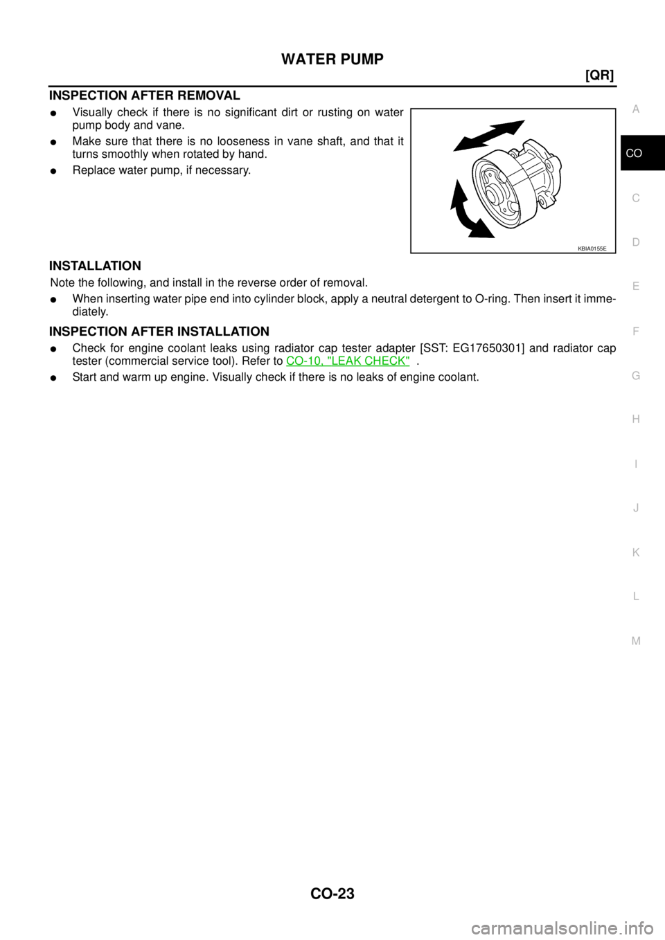
INSPECTION AFTER REMOVAL
�Visually check if there is no significant dirt or rusting on water
pump body and vane.
�Make sure that there is no looseness in vane shaft, and that it
turns smoothly when rotated by hand.
�Replace water pump, if necessary.
INSTALLATION
Note the following, and install in the reverse order of removal.
�When inserting water pipe end into cylinder block, apply a neutral detergent to O-ring. Then insert it imme-
diately.
INSPECTION AFTER INSTALLATION
�Check for engine coolant leaks using radiator cap tester adapter [SST: EG17650301] and radiator cap
tester (commercial service tool). Refer to CO-10, "
LEAK CHECK" .
�Start and warm up engine. Visually check if there is no leaks of engine coolant.
KBIA0155E
Page 977 of 3502
![NISSAN TEANA 2003 Service Manual THERMOSTAT AND WATER CONTROL VALVE
CO-25
[QR]
C
D
E
F
G
H
I
J
K
L
MA
CO
INSPECTION AFTER REMOVAL
�Place a string so that it is caught in the valves of thermostat and
water control valve. Immerse ful](/manual-img/5/57392/w960_57392-976.png "NISSAN TEANA 2003 Service Manual THERMOSTAT AND WATER CONTROL VALVE
CO-25
[QR]
C
D
E
F
G
H
I
J
K
L
MA
CO
INSPECTION AFTER REMOVAL
�Place a string so that it is caught in the valves of thermostat and
water control valve. Immerse ful")
THERMOSTAT AND WATER CONTROL VALVE
CO-25
[QR]
C
D
E
F
G
H
I
J
K
L
MA
CO
INSPECTION AFTER REMOVAL
�Place a string so that it is caught in the valves of thermostat and
water control valve. Immerse fully in a container filled with water.
Heat while stirring. (The example in the figure shows thermo-
stat.)
�The valve opening temperature is the temperature at which the
valve opens and falls from the thread.
�Continue heating. Check the maximum valve lift amount.
NOTE:
The maximum valve lift amount standard temperature for water
control valve is the reference value.
�After checking the maximum valve lift amount, lower the water
temperature and check the valve closing temperature.
Standard:
�If out of the standard, replace either or both thermostat and water control valve.
INSTALLATION
Note the following, and install in the reverse order of removal.
Thermostat and Water Control Valve
�Install thermostat with making rubber ring groove fit to thermo-
stat flange with the whole circumference. (The example in the
figure shows thermostat.)
NOTE:
Same procedure is applied for installation of water control valve.
�Install thermostat with jiggle valve facing upwards. (The position
deviation may be within the range of 20 degrees as shown in the
figure.)
�Install water control valve with the arrow facing up and the frame
center part facing upwards. (The position deviation may be
within the range of 20 degrees as shown in the figure.)
Heater Pipe Installation
Apply a neutral detergent to O-ring, then quickly insert the insertion part of heater pipe into cylinder block.
INSPECTION AFTER INSTALLATION
�Check for leaks of engine coolant using radiator cap tester adapter [SST: EG17650301] and a radiator cap
tester (commercial service tool). Refer to CO-10, "
LEAK CHECK" .
�Start and warm up engine. Visually check if there is no leaks of engine coolant and A/T fluid.
SLC252B
Items Thermostat Water control valve
Valve opening temperature 80.5 - 83.5°C (177 - 182°F) 93.5 - 96.5°C (200 - 206°F)
Maximum valve lift 8 mm/ 95°C (0.315 in/ 203°F) 8 mm/ 108°C (0.315 in/ 226°F)
Valve closing temperature 77°C (171°F) 90°C (194°F)
PBIC0157E
PBIC0158E
Page 990 of 3502
![NISSAN TEANA 2003 Service Manual CO-38
[VQ]
RADIATOR
5. Disconnect A/T fluid cooler hoses (VQ23DE), or CVT fluid cooler hoses (VQ35DE).
�Install plug to avoid leakage of A/T fluid or CVT fluid.
6. Remove radiator hoses (upper and l](/manual-img/5/57392/w960_57392-989.png "NISSAN TEANA 2003 Service Manual CO-38
[VQ]
RADIATOR
5. Disconnect A/T fluid cooler hoses (VQ23DE), or CVT fluid cooler hoses (VQ35DE).
�Install plug to avoid leakage of A/T fluid or CVT fluid.
6. Remove radiator hoses (upper and l")
CO-38
[VQ]
RADIATOR
5. Disconnect A/T fluid cooler hoses (VQ23DE), or CVT fluid cooler hoses (VQ35DE).
�Install plug to avoid leakage of A/T fluid or CVT fluid.
6. Remove radiator hoses (upper and lower) and reservoir tank hose.
7. Remove reservoir tank.
8. Remove battery and battery tray, and move fuse and fusible link block to aside. Refer to SC-4, "
BAT-
TERY" .
9. Remove mounting brackets to lift up and remove radiator and radiator cooling fan assembly.
CAUTION:
Do not damage or scratch A/C condenser and radiator core when removing.
10. Remove radiator cooling fan assembly from radiator.
INSTALLATION
Installation is the reverse order of removal.
INSPECTION AFTER INSTALLATION
�Check for leaks of engine coolant using radiator cap tester adapter [SST: EG17650301] and radiator cap
tester (commercial service tool). Refer to CO-34, "
LEAK CHECK" .
�Start and warm up engine. Visually check if there is no leaks of engine coolant and A/T fluid.
Checking Radiator CapBBS005AW
�Check valve seat of radiator cap.
–Check if valve seat is swollen to the extent that the edge of the
plunger cannot be seen when watching it vertically from the top.
–Check if valve seat has no soil and damage.
�Pull negative-pressure valve to open it, and make sure that it is
completely closed when released.
–Make sure that there is no dirt or damage on the valve seat of
radiator cap negative-pressure valve.
–Make sure that there are no unusualness in the opening and
closing conditions of negative-pressure valve.
�Check radiator cap relief pressure.
–When connecting radiator cap to the radiator cap tester (com-
mercial service tool) and the radiator cap tester adapter (SST),
apply engine coolant to the cap seal surface.
�Replace radiator cap if there is an unusualness related to the above three.
PBIC2816E
SMA967B
Standard:
78 - 98 kPa (0.78 - 0.98bar, 0.8 - 1.0 kg/cm
2 , 11 - 14 psi)
Limit:
59 kPa (0.59bar, 0.6 kg/cm
2 , 9 psi)
SLC755AC

![NISSAN TEANA 2003 Service Manual STEERING ANGLE SENSOR
BRC-91
[VDC/TCS/ABS]
C
D
E
G
H
I
J
K
L
MA
B
BRC
STEERING ANGLE SENSORPFP:25554
Removal and InstallationBFS000EU
REMOVAL
1. Remove spiral cable assembly. Refer to SRS-37, "SPIRA](/manual-img/5/57392/w960_57392-950.png "NISSAN TEANA 2003 Service Manual STEERING ANGLE SENSOR
BRC-91
[VDC/TCS/ABS]
C
D
E
G
H
I
J
K
L
MA
B
BRC
STEERING ANGLE SENSORPFP:25554
Removal and InstallationBFS000EU
REMOVAL
1. Remove spiral cable assembly. Refer to SRS-37, \"SPIRA")
![NISSAN TEANA 2003 Service Manual COOLING FAN
CO-21
[QR]
C
D
E
F
G
H
I
J
K
L
MA
CO
Disassembly and Assembly BBS005A9
DISASSEMBLY
1. Remove cooling fans (RH and LH) from fan motors.
2. Remove fan motors from fan shroud.
INSPECTION AF](/manual-img/5/57392/w960_57392-972.png "NISSAN TEANA 2003 Service Manual COOLING FAN
CO-21
[QR]
C
D
E
F
G
H
I
J
K
L
MA
CO
Disassembly and Assembly BBS005A9
DISASSEMBLY
1. Remove cooling fans (RH and LH) from fan motors.
2. Remove fan motors from fan shroud.
INSPECTION AF")