Page 1033 of 3502

TROUBLE DIAGNOSIS
CVT-27
D
E
F
G
H
I
J
K
L
MA
B
CVT
DIAGNOSTIC WORKSHEET
Information from Customer
KEY POINTS
�WHAT..... Vehicle & CVT model
�WHEN..... Date, Frequencies
�WHERE..... Road conditions
�HOW..... Operating conditions, Symptoms
Diagnostic Worksheet Chart
Customer name MR/MS Model & Year VIN
Trans. Model Engine Mileage
Malfunction Date Manuf. Date In Service Date
Frequency❏ Continuous❏ Intermittent ( times a day)
Symptoms❏ Vehicle does not move. (❏ Any position❏ Particular position)
❏ No shift
❏ Lock-up malfunction
❏ Shift shock or slip (❏ N → D❏ N → R❏ Lock-up❏ Any drive position)
❏ Noise or vibration
❏ No pattern select
❏ Others
()
1❏ Read the item on cautions concerning fail-safe and understand the customer's complaintCVT-24
2❏ CVT fluid inspection
CVT-32❏ Leak (Repair leak location.)
❏ Sta te
❏ Amount
3❏ Stall test and line pressure test
CVT-32
,
CVT-33
❏ Sta ll tes t
❏ Torque converter one-way clutch
❏ Reverse brake
❏ Forward clutch
❏ Steel belt❏ Engine
❏ Line pressure low
❏ Primary pulley
❏ Secondary pulley
❏ Line pressure inspection - Suspected part:
Page 1039 of 3502

TROUBLE DIAGNOSIS
CVT-33
D
E
F
G
H
I
J
K
L
MA
B
CVT
CAUTION:
Run the engine at idle for at least 1 minute.
10. Repeat steps 6 through 9 with selector lever in “R” position.
Judgement Stall Test
O: Stall speed within standard value position.
H: Stall speed is higher than standard value.
L: Stall speed is lower than standard value.
LINE PRESSURE TEST
Line Pressure Test Port
Line Pressure Test Procedure
1. Inspect the amount of engine oil and replenish if necessary.
2. Drive the car for about 10 minutes to warm it up so that the CVT fluid reaches in the range of 50 to 80°C
(122 to 176°F), then inspect the amount of CVT fluid and replenish if necessary.
NOTE:
The CVT fluid temperature rises in the range of 50 to 80°C (122 to 176°F) during 10 minutes of driv-
ing.
3. After warming up CVT, remove the oil pressure detection plug and install the oil pressure gauge. (Special
service tool: ST2505S001)
CAUTION:
When using the oil pressure gauge, be sure to use the O-ring attached to the oil pressure detec-
tion plug.
4. Securely engage the parking brake so that the tires do not turn.
Selector lever position
Expected problem location
“D” “R”
Stall rotation HO
�Forward clutch
OH
�Reverse brake
LL
�Engine and torque converter one-way clutch
HH
�Line pressure low
�Primary pulley
�Secondary pulley
�Steel belt
SCIA1980E
SCIA7463E
Page 1153 of 3502

DTC P1740 LOCK-UP SELECT SOLENOID VALVE CIRCUIT
CVT-147
D
E
F
G
H
I
J
K
L
MA
B
CVT
DTC P1740 LOCK-UP SELECT SOLENOID VALVE CIRCUITPFP:31941
DescriptionBCS001LF
�Lock-up select solenoid valve controls lock-up clutch pressure or forward clutch pressure (reverse brake
pressure).
�When controlling lock-up clutch, the valve is turned OFF. When controlling forward clutch, it is turned ON.
CONSULT-II Reference ValueBCS001LG
On Board Diagnosis LogicBCS001LH
Diagnostic trouble code “P1740 LU-SLCT SOL/CIRC” with CONSULT-II is detected under the following condi-
tions.
�When TCM compares target value with monitor value and detects an irregularity.
Possible CauseBCS001LI
�Lock-up select solenoid valve
�Harness or connectors
(Solenoid circuit is open or shorted.)
DTC Confirmation ProcedureBCS001LJ
CAUTION:
Always drive vehicle at a safe speed.
NOTE:
If “DTC Confirmation Procedure” has been previously performed, always turn ignition switch OFF and
wait at least 10 seconds before performing the next test.
After the repair, touch “ERASE” on “SELF-DIAG RESULTS” and then perform the following procedure to con-
firm the malfunction is eliminated.
WITH CONSULT-II
1. Turn ignition switch ON. (Do not start engine.)
2. Select “DATA MONITOR” mode for “TRANSMISSION” with
CONSULT-II.
3. Start engine and maintain the following conditions for at least 5
consecutive seconds.
RANGE: “D” position and “N” position
(At each time, wait for 5 seconds.)
4. If DTC is detected, go to CVT-149, "
Diagnostic Procedure" .
Item name Condition Display value
LUSEL SOL OUTSelector lever in “P”, “N” positions ON
Wait at least for 5 seconds with the selector
lever in “R”, “D” positionsOFF
BCIA0031E
Page 1181 of 3502
TRANSMISSION CONTROL MODULE
CVT-175
D
E
F
G
H
I
J
K
L
MA
B
CVT
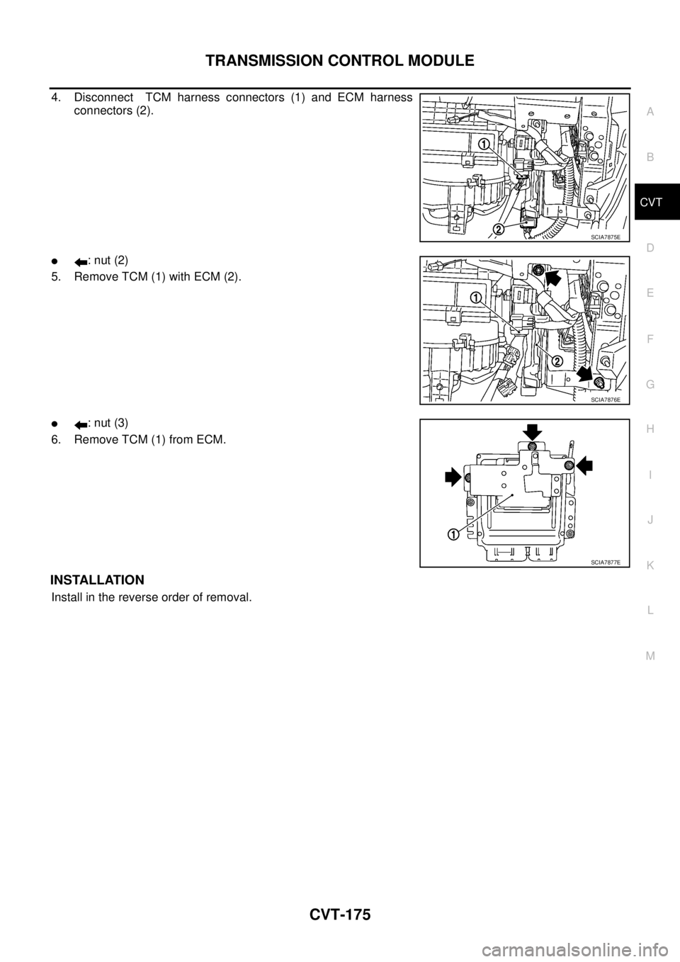
4. Disconnect TCM harness connectors (1) and ECM harness
connectors (2).
�: nut (2)
5. Remove TCM (1) with ECM (2).
�: nut (3)
6. Remove TCM (1) from ECM.
INSTALLATION
Install in the reverse order of removal.
SCIA7875E
SCIA7876E
SCIA7877E
Page 1184 of 3502

CVT-178
SHIFT CONTROL SYSTEM
8. Remove control device assembly.
INSTALLATION
Note the following, and install in the reverse order of removal.
�The knurled surface of rib should be upward when installing the
control cable to the control device assembly. And insert the con-
trol cable securely.
�After installation is completed, adjust and check CVT position.
Refer to CVT-178, "
Adjustment of CVT Position" and CVT-179,
"Checking of CVT Position" .
Adjustment of CVT PositionBCS001MN
1. Place selector lever in “P” position.
2. Loosen control cable nut and place manual lever in “P” position.
CAUTION:
Turn wheels more than 1/4 rotations and apply the park
lock.
3. Hold the control cable at the end. Push and pull it twice or three
times, and then push it with a load of 9.8N (approximately 1 kg,
2.2 lb). Temporarily tighten the lock nut with the control cable
loose.
4. Connect control cable on manual lever.
CAUTION:
No application of a force to the manual lever.
5. Tighten control cable nut.
CAUTION:
Fix the manual lever when tightening.
SCIA5964E
SCIA5990E
: 12.7 N·m (1.3 kg-m, 9 ft-lb)
SCIA2001E
Page 1192 of 3502
CVT-186
AIR BREATHER HOSE
AIR BREATHER HOSEPFP:31098
Removal and InstallationBCS001MV
COMPONENTS
REMOVAL
Refer to the figure for air breather hose removal procedure.
INSTALLATION
Note the following, and install in the reverse order of removal.
�Install air breather hose (1) to air breather tube (2) so that the
paint mark (A) faces leftward. Also make sure air breather hose
end laps with air breather tube 17 mm (0.67 in) or more.
�When installing air breather hose (1) to air duct assembly, make
sure to fully insert the hose with clip (2).
1. Air duct assembly 2. Transmission assembly 3. Air breather tube
4. Air breather hose
SCIA7895E
SCIA7896E
SCIA7897E
Page 1198 of 3502

CVT-192
CVT FLUID COOLER SYSTEM
INSTALLATION
Note the following, and install in the reverse order of removal.
�After completing installation, check for engine coolant leakage, engine coolant level, and the positions of
CVT. Refer to CO-34, "
Inspection" and CVT-179, "Checking of CVT Position" .
CAUTION:
�Install hose clamp with tabs aligned with markings of CVT fluid cooler valve assembly and each
hose.
�Do not reuse CVT fluid cooler inlet tube assembly and CVT fluid cooler outlet tube assembly.
�Apply LLC around O-ring when installing CVT fluid cooler inlet tube and CVT fluid cooler outlet
tube assembly to CVT fluid cooler valve assembly.
COMPONENT INSPECTION
1. Make sure that CVT fluid cooler valve is fully opened at room
temperature.
2. Put CVT fluid cooler valve into a water-filled container, and then
heat it up to 82°C (180°F) or more for 10 minutes or more.
3. Make sure that CVT fluid cooler valve is fully closed.Standard
Dimension A from CVT fluid cooler valve port end
to tip of valve shaft
(At room temperature):
Approx 72.0 mm (2.835 in) or more
SCIA7399E
SCIA2710E
Standard
Dimension A from CVT fluid cooler valve port end
to tip of valve shaft
[When heating to 82°C (180°F) or more for 10 min-
utes or more]:
Approx 66.5 mm (2.618 in) or less
SCIA7399E
Page 1202 of 3502
CVT-196
TRANSAXLE ASSEMBLY
INSPECTION
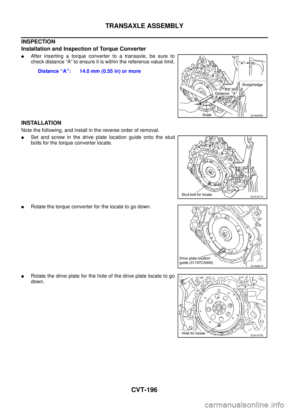
Installation and Inspection of Torque Converter
�After inserting a torque converter to a transaxle, be sure to
check distance “A” to ensure it is within the reference value limit.
INSTALLATION
Note the following, and install in the reverse order of removal.
�Set and screw in the drive plate location guide onto the stud
bolts for the torque converter locate.
�Rotate the torque converter for the locate to go down.
�Rotate the drive plate for the hole of the drive plate locate to go
down.Distance “A”: 14.0 mm (0.55 in) or more
SCIA6858E
SCIA1871E
SCIA6881E
SCIA1872E