Page 23 of 3502
A/T FLUID
AT-15
D
E
F
G
H
I
J
K
L
MA
B
AT
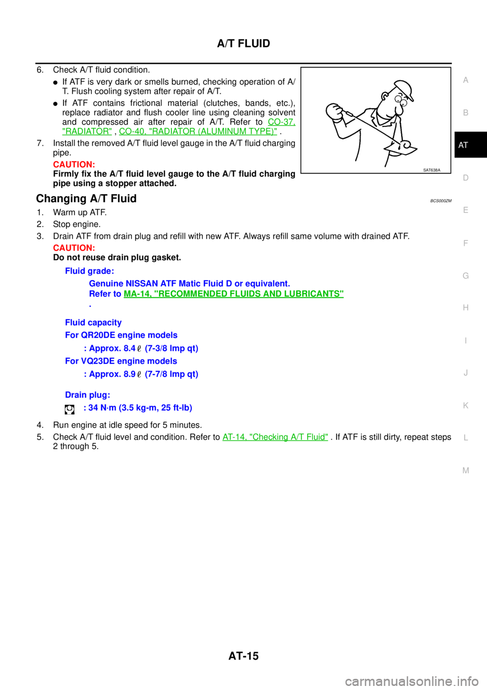
6. Check A/T fluid condition.
�If ATF is very dark or smells burned, checking operation of A/
T. Flush cooling system after repair of A/T.
�If ATF contains frictional material (clutches, bands, etc.),
replace radiator and flush cooler line using cleaning solvent
and compressed air after repair of A/T. Refer to CO-37,
"RADIATOR" , CO-40, "RADIATOR (ALUMINUM TYPE)" .
7. Install the removed A/T fluid level gauge in the A/T fluid charging
pipe.
CAUTION:
Firmly fix the A/T fluid level gauge to the A/T fluid charging
pipe using a stopper attached.
Changing A/T FluidBCS000ZM
1. Warm up ATF.
2. Stop engine.
3. Drain ATF from drain plug and refill with new ATF. Always refill same volume with drained ATF.
CAUTION:
Do not reuse drain plug gasket.
4. Run engine at idle speed for 5 minutes.
5. Check A/T fluid level and condition. Refer to AT- 1 4 , "
Checking A/T Fluid" . If ATF is still dirty, repeat steps
2 through 5.
SAT638A
Fluid grade:
Genuine NISSAN ATF Matic Fluid D or equivalent.
Refer to MA-14, "
RECOMMENDED FLUIDS AND LUBRICANTS"
.
Fluid capacity
For QR20DE engine models
: Approx. 8.4 (7-3/8 lmp qt)
For VQ23DE engine models
: Approx. 8.9 (7-7/8 lmp qt)
Drain plug:
: 34 N·m (3.5 kg-m, 25 ft-lb)
Page 234 of 3502
AT-226
ON-VEHICLE SERVICE
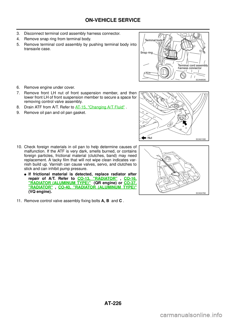
3. Disconnect terminal cord assembly harness connector.
4. Remove snap ring from terminal body.
5. Remove terminal cord assembly by pushing terminal body into
transaxle case.
6. Remove engine under cover.
7. Remove front LH nut of front suspension member, and then
lower front LH of front suspension member to secure a space for
removing control valve assembly.
8. Drain ATF from A/T. Refer to AT- 1 5 , "
Changing A/T Fluid" .
9. Remove oil pan and oil pan gasket.
10. Check foreign materials in oil pan to help determine causes of
malfunction. If the ATF is very dark, smells burned, or contains
foreign particles, frictional material (clutches, band) may need
replacement. A tacky film that will not wipe clean indicates var-
nish build up. Varnish can cause valves, servo, and clutches to
stick and can inhibit pump pressure.
�If frictional material is detected, replace radiator after
repair of A/T. Refer to CO-13, "
RADIATOR" , CO-16,
"RADIATOR (ALUMINUM TYPE)" (QR engine) or CO-37,
"RADIATOR" , CO-40, "RADIATOR (ALUMINUM TYPE)"
(VQ engine).
11. Remove control valve assembly fixing bolts A, B and C .
SCIA4853E
SCIA3153E
SCIA3476E
Page 264 of 3502

AT-256
DISASSEMBLY
5. Set manual shaft to “P” position.
6. Remove PNP switch.
7. Remove bracket from transaxle case.
8. Remove revolution sensor from transaxle case.
9. Remove O-ring from revolution sensor.
10. Remove turbine revolution sensor (power train revolution sen-
sor) from transaxle case.
11. Remove O-ring from turbine revolution sensor (power train revo-
lution sensor).
12. Remove oil pan fitting bolts.
13. Remove oil pan and oil pan gasket.
14. Check foreign materials in oil pan to help determine causes of
malfunction. If the ATF is very dark, smells burned, or contains
foreign particles, frictional material (clutches, band) may need
replacement. A tacky film that will not wipe clean indicates var-
nish build up. Varnish can cause valves, servo, and clutches to
stick and can inhibit pump pressure.
�If frictional material is detected, replace radiator after
repair of A/T.
15. Remove magnets from oil pan.
16. Remove control valve assembly according to the following procedures.
a. Remove snap ring from terminal body.
CAUTION:
Do not expand snap ring excessively.
b. Push terminal body into transaxle case and draw out terminal
cord assembly.
SCIA3154E
SCIA3476E
SCIA4866E
SCIA0801E
Page 469 of 3502
TROUBLE DIAGNOSIS
ATC-91
C
D
E
F
G
H
I
K
L
MA
B
AT C
Insufficient HeatingBJS000G8
SYMPTOM: Insufficient heating
INSPECTION FLOW
*1ATC-54, "Operational Check"*2ATC-66, "Air Mix Door Motor Circuit"*3AT C - 4 7 , "FUNCTION CONFIRMA-
TION PROCEDURE", see No. 2 to
6.
*4ATC-47, "
FUNCTION CONFIRMA-
TION PROCEDURE", see No. 13.*5ATC-59, "
LAN System Circuit"*6AT C - 7 2 , "Blower Motor Circuit"
*7EC-131, "DTC P0117, P0118 ECT
SENSOR" (QR engine) or EC-474,
"DTC P0117, P0118 ECT SEN-
SOR" (VQ engine)*8CO-10, "
Changing Engine Coolant"
(QR engine) or CO-34, "
Changing
Engine Coolant" (VQ engine)*9CO-14, "
Checking Radiator Cap"
(QR engine) or CO-38, "
Checking
Radiator Cap" (VQ engine)
RJIA3273E
Page 498 of 3502
ATC-120
HEATER & COOLING UNIT ASSEMBLY
10. Remove mounting bolts from heater & cooling unit.
11. Remove steering column mounting nuts.
12. Remove steering member mounting bolts.
13. Remove steering member, and then remove heater & cooling unit.
INSTALLATION
Installation is basically the reverse order of removal.
CAUTION:
�Replace O-rings of A/C piping with new ones, and then apply compressor oil to it when installing
it.
�Female-side piping connection is thin and easy to deform. Slowly insert the male-side piping
straight in axial direction.
�Insert piping securely until a click is heard.
�After piping connection is completed, pull male-side piping by hand to make sure that connection
does not come loose.
�When recharging refrigerant, check for leaks.
NOTE:
�When filling radiator with coolant, refer to CO-10, "Changing Engine Coolant" (QR engine) or CO-34,
"Changing Engine Coolant" (VQ engine).
�Recharge the refrigerant.
RJIA3303E
RJIA3304E
Page 517 of 3502
REFRIGERANT LINES
ATC-139
C
D
E
F
G
H
I
K
L
MA
B
AT C
Removal and Installation of High-pressure Pipe 1 (Engine Compartment)BJS000HT
REMOVAL
1. Use a refrigerant collecting equipment (for HFC-134a) to discharge the refrigerant.
2. Remove extension cowl top lower panel. Refer to EI-21, "
COWL TOP" .
3. Remove low-pressure flexible hose and low-pressure pipe 1 (VQ engine). Refer to ATC-137, "
Removal
and Installation of Low-pressure Flexible Hose and Low-pressure Pipe 1" .
4. Remove radiator reservoir tank. Refer to CO-13, "
RADIATOR" (QR engine) or CO-37, "RADIATOR" (VQ
engine).
5. Remove IPDM E/R. Refer to PG-28, "
Removal and Installation of IPDM E/R" .
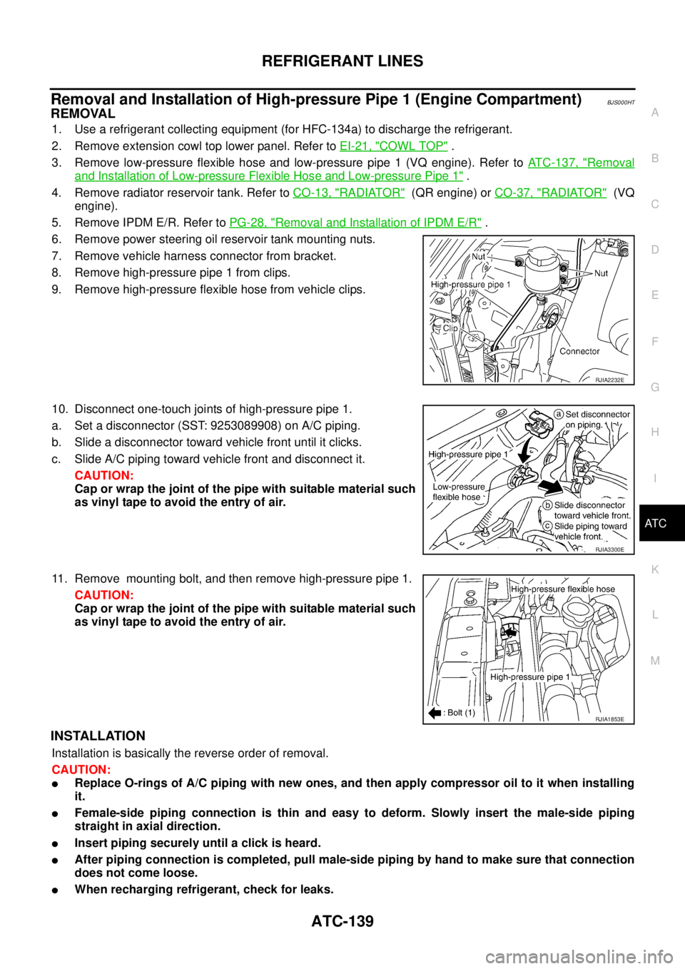
6. Remove power steering oil reservoir tank mounting nuts.
7. Remove vehicle harness connector from bracket.
8. Remove high-pressure pipe 1 from clips.
9. Remove high-pressure flexible hose from vehicle clips.
10. Disconnect one-touch joints of high-pressure pipe 1.
a. Set a disconnector (SST: 9253089908) on A/C piping.
b. Slide a disconnector toward vehicle front until it clicks.
c. Slide A/C piping toward vehicle front and disconnect it.
CAUTION:
Cap or wrap the joint of the pipe with suitable material such
as vinyl tape to avoid the entry of air.
11. Remove mounting bolt, and then remove high-pressure pipe 1.
CAUTION:
Cap or wrap the joint of the pipe with suitable material such
as vinyl tape to avoid the entry of air.
INSTALLATION
Installation is basically the reverse order of removal.
CAUTION:
�Replace O-rings of A/C piping with new ones, and then apply compressor oil to it when installing
it.
�Female-side piping connection is thin and easy to deform. Slowly insert the male-side piping
straight in axial direction.
�Insert piping securely until a click is heard.
�After piping connection is completed, pull male-side piping by hand to make sure that connection
does not come loose.
�When recharging refrigerant, check for leaks.
RJIA2232E
RJIA3300E
RJIA1853E
Page 520 of 3502
ATC-142
REFRIGERANT LINES
Removal and Installation of CondenserBJS000HV
REMOVAL
1. Use a refrigerant collecting equipment (for HFC-134a) to discharge the refrigerant.
2. Remove air duct (inlet). Refer to EM-17, "
AIR CLEANER AND AIR DUCT" (QR engine) or EM-131, "AIR
CLEANER AND AIR DUCT" (VQ engine).
3. Remove front grille. Refer to EI-20, "
FRONT GRILLE" .
4. Remove battery. Refer to SC-4, "
BATTERY" .
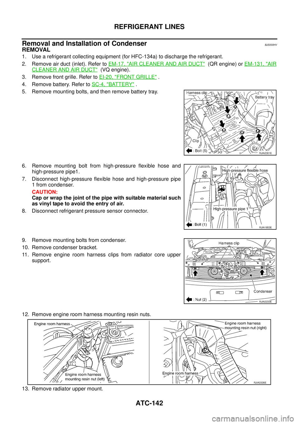
5. Remove mounting bolts, and then remove battery tray.
6. Remove mounting bolt from high-pressure flexible hose and
high-pressure pipe1.
7. Disconnect high-pressure flexible hose and high-pressure pipe
1 from condenser.
CAUTION:
Cap or wrap the joint of the pipe with suitable material such
as vinyl tape to avoid the entry of air.
8. Disconnect refrigerant pressure sensor connector.
9. Remove mounting bolts from condenser.
10. Remove condenser bracket.
11. Remove engine room harness clips from radiator core upper
support.
12. Remove engine room harness mounting resin nuts.
13. Remove radiator upper mount.
RJIA2301E
RJIA1853E
RJIA2233E
RJIA3326E
Page 521 of 3502
REFRIGERANT LINES
ATC-143
C
D
E
F
G
H
I
K
L
MA
B
AT C
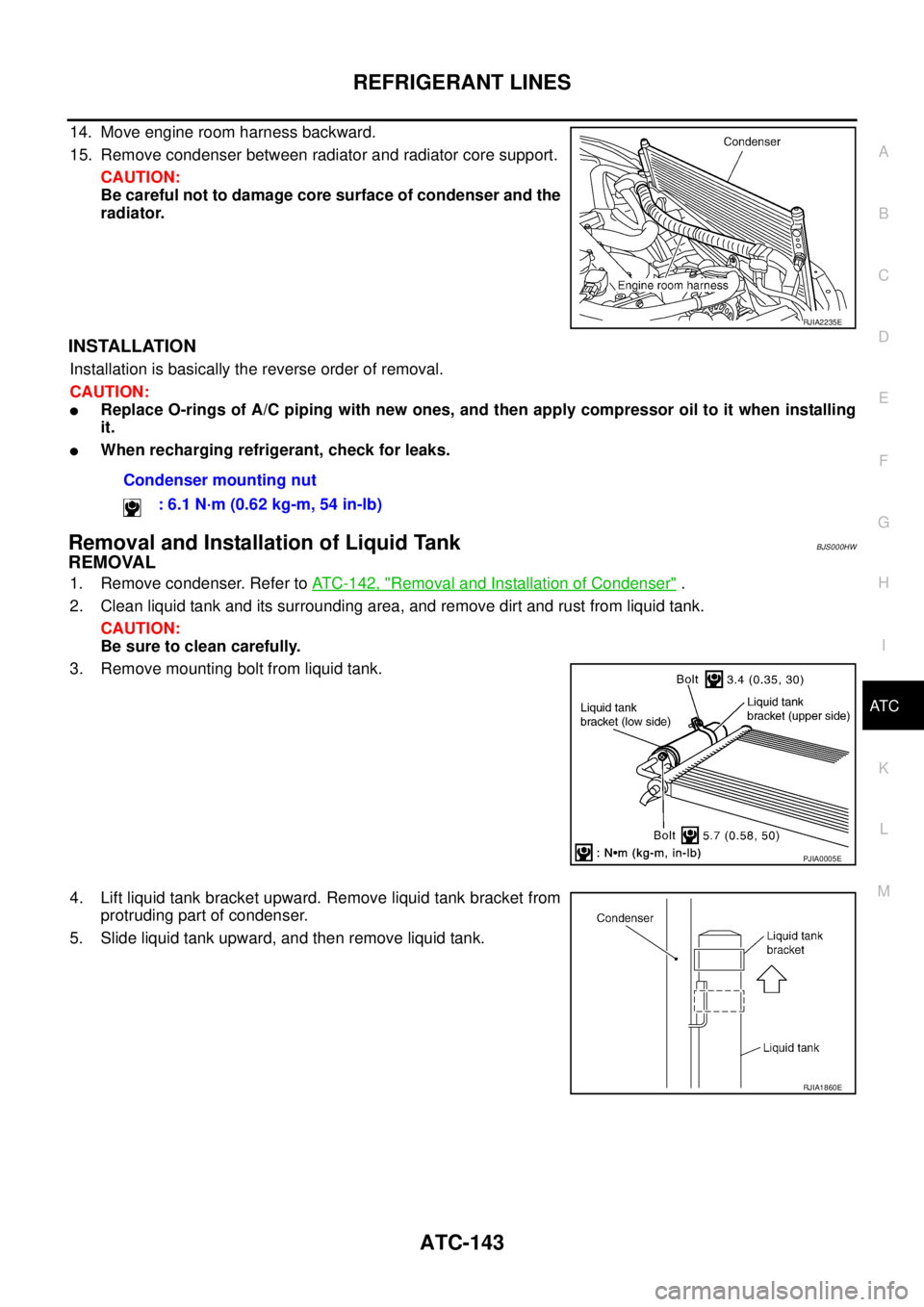
14. Move engine room harness backward.
15. Remove condenser between radiator and radiator core support.
CAUTION:
Be careful not to damage core surface of condenser and the
radiator.
INSTALLATION
Installation is basically the reverse order of removal.
CAUTION:
�Replace O-rings of A/C piping with new ones, and then apply compressor oil to it when installing
it.
�When recharging refrigerant, check for leaks.
Removal and Installation of Liquid TankBJS000HW
REMOVAL
1. Remove condenser. Refer to ATC-142, "Removal and Installation of Condenser" .
2. Clean liquid tank and its surrounding area, and remove dirt and rust from liquid tank.
CAUTION:
Be sure to clean carefully.
3. Remove mounting bolt from liquid tank.
4. Lift liquid tank bracket upward. Remove liquid tank bracket from
protruding part of condenser.
5. Slide liquid tank upward, and then remove liquid tank.
RJIA2235E
Condenser mounting nut
: 6.1 N·m (0.62 kg-m, 54 in-lb)
PJIA0005E
RJIA1860E