Page 240 of 3502
AT-232
ON-VEHICLE SERVICE
3. Remove differential side oil seals using a flat-bladed screw-
driver.
CAUTION:
Be careful not to scratch transaxle case and converter
housing.
Installation
1. Drive differential side oil seals using the drift below into case
until it become flush. Refer to dimensions “A” and “B”.
Unit: mm (in)
NOTE:
Differential side oil seal pulling direction is used as the refer-
ence.
Drift to be used:
CAUTION:
�Do not reuse differential side oil seals.
�Apply ATF to differential side oil seals.
2. Reinstall any part removed.
CAUTION:
If lubricant leak has occurred, after finishing work, check A/T fluid level. Refer to AT- 1 4 , "
Checking
A/T Fluid" .
SCIA4857E
Dimensions “A”, “B” 0± 0.5 (0±0.020)
SCIA4858E
Location Tool number
Transaxle case side (left) ST33400001
Converter housing side (right) ST33400001
SCIA4739E
Page 347 of 3502
ASSEMBLY
AT-339
D
E
F
G
H
I
J
K
L
MA
B
AT
ASSEMBLYPFP:00000
Assembly (1)BCS001OW
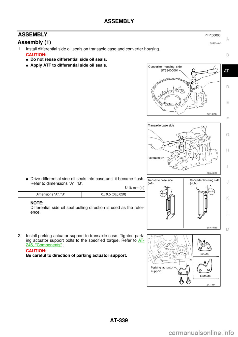
1. Install differential side oil seals on transaxle case and converter housing.
CAUTION:
�Do not reuse differential side oil seals.
�Apply ATF to differential side oil seals.
�Drive differential side oil seals into case until it became flush.
Refer to dimensions “A”, “B”.
Unit: mm (in)
NOTE:
Differential side oil seal pulling direction is used as the refer-
ence.
2. Install parking actuator support to transaxle case. Tighten park-
ing actuator support bolts to the specified torque. Refer to AT-
246, "Components" .
CAUTION:
Be careful to direction of parking actuator support.
SAT181FC
SCIA4913E
Dimensions “A”, “B” 0± 0.5 (0±0.020)
SCIA4858E
SAT183F
Page 350 of 3502

AT-342
ASSEMBLY
b. Place idler gear bearing on transaxle case.
c. Measure dimensions “B”, “C” and “D” and calculate dimension
“A”.
�Measure dimension “B” between the end of reduction pinion
gear and the surface of transaxle case.
�Measure dimension “B” in at least two places.
�Measure dimension “C” between the surface of idler gear
bearing inner race and the surface of transaxle case.
�Measure dimension “C” in at least two places.
�Measure dimension “D” between the end of reduction pinion
gear and the adjusting shim mating surface of reduction pin-
ion gear.
�Measure dimension “D” in at least two places.
�Calculate dimension “A”.
d. Measure dimension “E” between the end of idler gear and idler
gear bearing inner race mating surface of idler gear.
�Measure dimension “E” in at least two places.
e. Select proper thickness of reduction pinion gear bearing adjust-
ing shim. Refer to “Parts Information” for reduction pinion gear
bearing adjusting shims selection.A = D − (B + C)
“A”: Distance between the surface of idler gear
bearing inner race and the adjusting shim
mating surface of reduction pinion gear.
SCIA3624E
SCIA3625E
SCIA3626E
A = D − (B + C)
SAT336DA
Proper shim thickness = A − E − 0.05 mm (0.0020 in)*
(*: Bearing preload)
SAT337D
Page 353 of 3502

ASSEMBLY
AT-345
D
E
F
G
H
I
J
K
L
MA
B
AT
4. Measure dimensions “1 ” and “2 ” at side cover and then cal-
culate dimension “A”.
�Measure dimension “ 1” and “ 2” in at least two places.
5. Measure dimensions “
2 ” and “3 ” and then calculate dimen-
sion “B”.
�Measure dimension “ 2” and “ 3” in at least two places.
6. Select proper thickness of output shaft adjusting shim so that
output shaft end play (clearance between side cover and output
shaft bearing) is within specifications. Refer to “Parts Informa-
tion” for output shaft adjusting shim selection.
7. Install output shaft adjusting shim on output shaft bearing.
Assembly (2)BCS001OY
1. Apply locking sealant (Loctite # 518) to transaxle case as shown
in figure.
CAUTION:
Completely remove all moisture, oil and old sealant, etc.
from the transaxle case and side cover mounting surfaces.
2. Fit mounting part of output shaft bearing on side cover to output
shaft bearing, and after adjusting knock pin position, install it
with light taps of a soft hammer and things like that.
CAUTION:
When installing, to avoid getting damaged and deformed,
set mounting part straight to parallel with the mounting sur-
face.“A”: Distance between transaxle case fitting sur-
face and adjusting shim mating surface.
A =
1 − 2
2
: Height of gauge
SAT374F
“B”: Distance between the end of output shaft
bearing outer race and the side cover fitting
surface of transaxle case.
B =
2 − 3
2
: Height of gauge
SAT375F
Output shaft end play (A − B):
Refer to AT- 3 6 8 , "
Output Shaft" .
SCIA4918E
SCIA4919E
SAT442D
Page 360 of 3502
AT-352
ASSEMBLY
18. Install reverse clutch assembly on input shaft assembly (high
clutch drum).
Adjustment (2)BCS001OZ
When any parts listed below are replaced, adjust total end play and reverse clutch end play.
TOTAL END PLAY
�Measure clearance between reverse clutch drum and needle
bearing for oil pump cover.
�Select proper thickness of bearing race so that end play is within
specifications.
1. Measure dimensions “K” and “L” and then calculate dimension
“J”.
SCIA4461E
Part name Total end play Reverse clutch end play
transaxle case��
Overrun clutch hub��
Rear internal gear��
Rear planetary carrier��
Rear sun gear��
Front planetary carrier��
Front sun gear��
High clutch hub��
Input shaft assembly (high clutch drum)��
Oil pump cover��
Reverse clutch drum —�
SCIA3661E
SCIA3662E
Page 362 of 3502
AT-354
ASSEMBLY
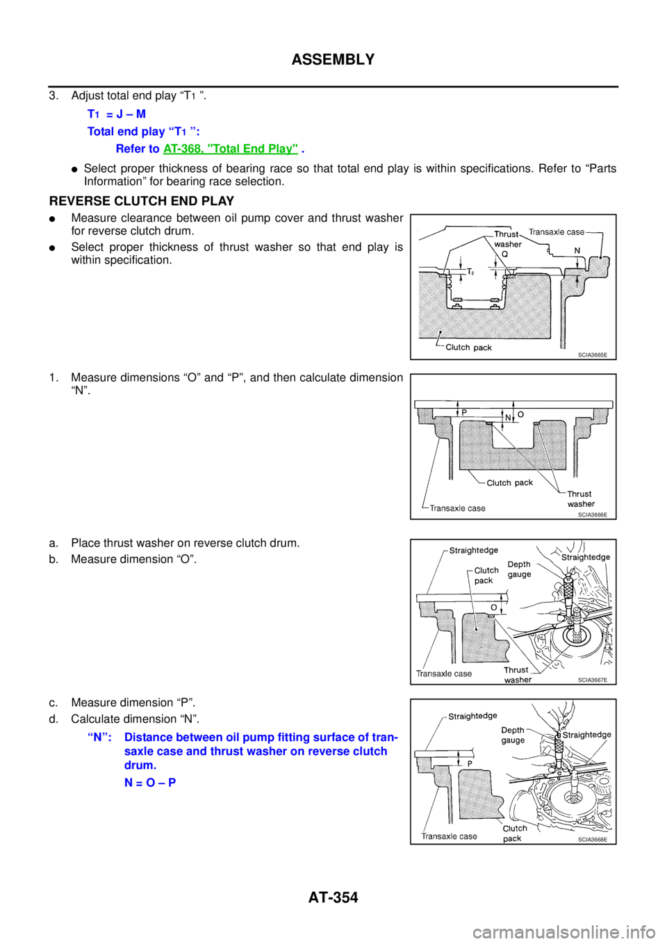
3. Adjust total end play “T1 ”.
�Select proper thickness of bearing race so that total end play is within specifications. Refer to “Parts
Information” for bearing race selection.
REVERSE CLUTCH END PLAY
�Measure clearance between oil pump cover and thrust washer
for reverse clutch drum.
�Select proper thickness of thrust washer so that end play is
within specification.
1. Measure dimensions “O” and “P”, and then calculate dimension
“N”.
a. Place thrust washer on reverse clutch drum.
b. Measure dimension “O”.
c. Measure dimension “P”.
d. Calculate dimension “N”.T
1 = J – M
Total end play “T
1 ”:
Refer to AT- 3 6 8 , "
Total End Play" .
SCIA3665E
SCIA3666E
SCIA3667E
“N”: Distance between oil pump fitting surface of tran-
saxle case and thrust washer on reverse clutch
drum.
N = O – P
SCIA3668E
Page 363 of 3502
ASSEMBLY
AT-355
D
E
F
G
H
I
J
K
L
MA
B
AT
2. Measure dimensions “R” and “S”, and then calculate dimension
“Q”.
a. Measure dimension “R”.
b. Measure dimension “S”.
c. Calculate dimension “Q”.
3. Adjust reverse clutch end play “T
2 ”.
�Select proper thickness of thrust washer so that reverse clutch end play is within specifications. Refer
to “Parts Information” for thrust washer selection.
Assembly (3)BCS001P0
1. Install anchor end pin and lock nut on transaxle case.
CAUTION:
Do not reuse anchor end pin.
2. Place brake band and strut on outside of reverse clutch drum.
Tighten anchor end pin just enough so that brake band is evenly
fitted on reverse clutch drum.
SAT384D
SAT385D
“Q”: Distance between transaxle case fitting sur-
face and thrust washer mating surface.
Q = R – S
SAT386D
T2 = N – Q
Reverse clutch end play:
Refer to AT- 3 6 8 , "
Reverse Clutch End Play" .
SAT196F
Page 955 of 3502
![NISSAN TEANA 2003 Service Manual PRECAUTIONS
CO-3
[QR]
C
D
E
F
G
H
I
J
K
L
MA
CO
[QR]PRECAUTIONSPFP:00001
Precautions for Supplemental Restraint System (SRS) “AIR BAG” and “SEAT
BELT PRE-TENSIONER”
BBS0059V
The Supplementa](/manual-img/5/57392/w960_57392-954.png "NISSAN TEANA 2003 Service Manual PRECAUTIONS
CO-3
[QR]
C
D
E
F
G
H
I
J
K
L
MA
CO
[QR]PRECAUTIONSPFP:00001
Precautions for Supplemental Restraint System (SRS) “AIR BAG” and “SEAT
BELT PRE-TENSIONER”
BBS0059V
The Supplementa")
PRECAUTIONS
CO-3
[QR]
C
D
E
F
G
H
I
J
K
L
MA
CO
[QR]PRECAUTIONSPFP:00001
Precautions for Supplemental Restraint System (SRS) “AIR BAG” and “SEAT
BELT PRE-TENSIONER”
BBS0059V
The Supplemental Restraint System such as “AIR BAG” and “SEAT BELT PRE-TENSIONER”, used along
with a front seat belt, helps to reduce the risk or severity of injury to the driver and front passenger for certain
types of collision. Information necessary to service the system safely is included in the SRS and SB section of
this Service Manual.
WARNING:
�To avoid rendering the SRS inoperative, which could increase the risk of personal injury or death
in the event of a collision which would result in air bag inflation, all maintenance must be per-
formed by an authorized NISSAN/INFINITI dealer.
�Improper maintenance, including incorrect removal and installation of the SRS, can lead to per-
sonal injury caused by unintentional activation of the system. For removal of Spiral Cable and Air
Bag Module, see the SRS section.
�Do not use electrical test equipment on any circuit related to the SRS unless instructed to in this
Service Manual. SRS wiring harnesses can be identified by yellow and/or orange harnesses or
harness connectors.
Precautions for Liquid GasketBBS005AV
REMOVAL OF LIQUID GASKET SEALING
�After removing mounting nuts and bolts, separate the mating
surface using seal cutter (SST) and remove old liquid gasket
sealing.
CAUTION:
Be careful not to damage the mating surfaces.
�Tap seal cutter to insert it, and then slide it by tapping on the
side as shown in the figure.
�In areas where seal cutter (SST) is difficult to use, use plastic
hammer to lightly tap the parts, to remove it.
CAUTION:
If for some unavoidable reason tool such as screwdriver is
used, be careful not to damage the mating surfaces.
LIQUID GASKET APPLICATION PROCEDURE
1. Using scraper, remove old liquid gasket adhering to the liquid
gasket application surface and the mating surface.
�Remove liquid gasket completely from the groove of the liquid
gasket application surface, mounting bolts, and bolt holes.
2. Wipe the liquid gasket application surface and the mating sur-
face with white gasoline (lighting and heating use) to remove
adhering moisture, grease and foreign materials.
3. Attach liquid gasket tube to tube presser (SST).
Use Genuine Liquid Gasket or equivalent.
4. Apply liquid gasket without breaks to the specified location with
the specified dimensions.
�If there is a groove for the liquid gasket application, apply liq-
uid gasket to the groove.
PBIC0275E
PBIC0003E
PBIC2160E

.
Adjustment (2)BCS001OZ
When any parts listed below are replaced, adjust total end play and reverse clu")