Page 84 of 3502

AT-76
TROUBLE DIAGNOSIS
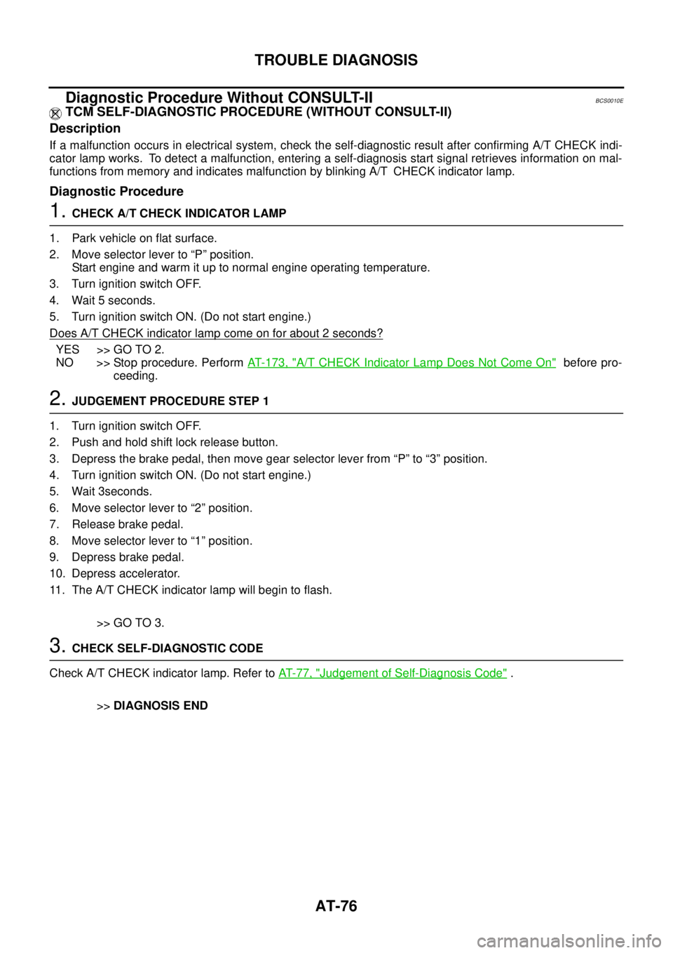
Diagnostic Procedure Without CONSULT-IIBCS0010E
TCM SELF-DIAGNOSTIC PROCEDURE (WITHOUT CONSULT-II)
Description
If a malfunction occurs in electrical system, check the self-diagnostic result after confirming A/T CHECK indi-
cator lamp works. To detect a malfunction, entering a self-diagnosis start signal retrieves information on mal-
functions from memory and indicates malfunction by blinking A/T CHECK indicator lamp.
Diagnostic Procedure
1. CHECK A/T CHECK INDICATOR LAMP
1. Park vehicle on flat surface.
2. Move selector lever to “P” position.
Start engine and warm it up to normal engine operating temperature.
3. Turn ignition switch OFF.
4. Wait 5 seconds.
5. Turn ignition switch ON. (Do not start engine.)
Does A/T CHECK indicator lamp come on for about 2 seconds?
YES >> GO TO 2.
NO >> Stop procedure. Perform AT- 1 7 3 , "
A/T CHECK Indicator Lamp Does Not Come On" before pro-
ceeding.
2. JUDGEMENT PROCEDURE STEP 1
1. Turn ignition switch OFF.
2. Push and hold shift lock release button.
3. Depress the brake pedal, then move gear selector lever from “P” to “3” position.
4. Turn ignition switch ON. (Do not start engine.)
5. Wait 3seconds.
6. Move selector lever to “2” position.
7. Release brake pedal.
8. Move selector lever to “1” position.
9. Depress brake pedal.
10. Depress accelerator.
11. The A/T CHECK indicator lamp will begin to flash.
>> GO TO 3.
3. CHECK SELF-DIAGNOSTIC CODE
Check A/T CHECK indicator lamp. Refer to AT- 7 7 , "
Judgement of Self-Diagnosis Code" .
>>DIAGNOSIS END
Page 751 of 3502

INTELLIGENT KEY SYSTEM
BL-93
C
D
E
F
G
H
J
K
L
MA
B
BL
CONSULT-II Functions (INTELLIGENT KEY)BIS001TD
CONSULT-II can display each diagnostic item using the diagnostic test modes as shown below.
CONSULT-II Inspection ProcedureBIS001TE
CAUTION:
If CONSULT-II is used with no connection CONSULT-II CONVERTER, malfunctions might be detected
in self-diagnosis depending on control unit which performs CAN Communication.
BASIC OPERATION
Refer to GI-34, "CONSULT-II Start Procedure" .
CONSULT-II Application ItemsBIS001TF
SELF-DIAGNOSTIC RESULTS
*: It is possible to display it only with the program card for engine immobilizer system.
DATA MONITOR
Part to be diagnosed Test item, Diagnosis mode Description
Intelligent KeyWORK SUPPORT Changes settings for each function.
SELF-DIAG RESULTS Intelligent Key unit performs CAN communication diagnosis.
DATA MONITOR Displays Intelligent Key unit input data in real time.
CAN DIAGNOSTIC SUPPORT
MONITORThe results of transmit/receive diagnosis of CAN Communication can
be read.
ACTIVE TESTOperation of electrical loads can be checked by sending driving signal
to then.
ECU PART NUMBER Displays Intelligent Key unit part No.
DTC Self-diag results Description Diagnosis procedureReference
page
U1000 CAN COMM CIRCUITMalfunction is detected in CAN communica-
tion.Check CAN communica-
tion system.BL-100
U1010 CONTROL UNIT (CAN) Intelligent Key unit internal malfunctionCheck CAN communica-
tion system.BL-100
B2013*STRG COMM CIRCUITMalfunction is detected in communication of
Intelligent Key unit and steering lock unit.Check steering lock unit.BL-115
B2552*INTELLIGENT KEY Intelligent Key unit internal malfunctionReplace Intelligent Key
unit.BL-117
B2590*DISCORD BCM - I-KEY Malfunction is detected in immobilizer system. Check NATS.BL-139
Monitor item Content
PUSH SW Indicates [ON/OFF] condition of ignition knob switch.
KEY SW Indicates [ON/OFF] condition of key switch.
DR REQ SW Indicates [ON/OFF] condition of door request switch (driver side).
AS REQ SW Indicates [ON/OFF] condition of door request switch (passenger side).
BD/TR REQ SW Indicates [ON/OFF] condition of trunk opener request switch.
IGN SW Indicates [ON/OFF] condition of ignition switch in ON position.
ACC SW Indicates [ON/OFF] condition of ignition switch in ACC position.
DOOR STAT SW Indicates [ON/OFF] condition of stop lamp switch.
STOP LAMP SW Indicates [ON/OFF] condition of door unlock sensor.
P RANGE SW* Indicates [ON/OFF] condition of park position switch.
DOOR LOCK SIG* Indicates [ON/OFF] condition of door lock signal from Intelligent Key remote controller button.
DOOR UNLOCK SIG* Indicates [ON/OFF] condition of door unlock signal from Intelligent Key remote controller button.
KEYLESS TRUNK* Indicates [ON/OFF] condition of trunk open signal from Intelligent Key remote controller button.
Page 3268 of 3502

SE-12
AUTOMATIC DRIVE POSITIONER
AUTOMATIC DRIVE POSITIONERPFP:28491
System Description BIS0012G
�The system automatically moves the driver seat to facilitate entry/exit to/from the vehicle. The automatic
drive positioner control unit can also store the optimum driving positions (driver seat) for 2 people. If the
driver is changes, one-touch operation allows changing to the other driving position.
�Using CONSULT-II, the seat slide amount at entry/exit setting can be changed.
MANUAL OPERATION
The driving position (seat position) can be adjusted with the power seat switch.
NOTE:
The seat can be manually operated with the ignition switch OFF.
A U T O M AT I C O P E R AT I O N
NOTE:
�Disconnecting the battery erases the stored memory.
�After connecting the battery, insert the key into the ignition cylinder and turn the driver door switch ON (open)→OFF (close)→ON
(open), the Entry/ Exiting operation becomes possible.
�After exiting operation is carried out, entry operation can be operated.
NOTE:
During automatic operation, if the ignition switch is turned ON→START, the automatic operation is suspended. When the ignition switch
returns to ON, it resumes.Function Description
Memory switch operation The seat move to the stored driving position by pushing memory switch (1 or 2).
Entry/Exiting functionExiting operation At exit, the seat moves backward.
Entry operation At entry, the seat returns from the exiting position to the previous driving position.
Keyfob interlock operation Perform memory operation and exiting operation by pressing keyfob unlock button.
Auto operation temporary stop
conditions.When ignition switch turned to START during memory switch operation and return opera-
tion, memory switch operation and entry operation is stopped.
Auto operation stop conditions.
�When the vehicle speed becomes 7 km/h (4 MPH) or higher.
�When the setting switch, memory switch 1, or 2 are pressed.
�When A/T or CVT selector lever is in any position other than P.
�When power seat switch turned ON.
�When driver seat sliding Entry/Exiting setting is OFF (only entry/exiting operation).