Page 465 of 3502

TROUBLE DIAGNOSIS
ATC-87
C
D
E
F
G
H
I
K
L
MA
B
AT C
PERFORMANCE CHART
Test Condition
Testing must be performed as follows:
Test Reading
Recirculating-to-discharge Air Temperature Table
Ambient Air Temperature-to-operating Pressure Table
Vehicle condition Indoors or in the shade (in a well-ventilated place)
Doors Closed
Door windows Open
Hood Open
TEMP. Max. COLD
Mode switch
(Ventilation) set
Intake switch
(Recirculation) set
Fan (blower) speedMax. speed set
Engine speed Idle speed
Operate the air conditioning system for 10 minutes before taking measurements.
Inside air (Recirculating air) at blower assembly inlet
Discharge air temperature at center ventilator
°C (°F) Relative humidity
%Air temperature
°C (°F)
50 - 6020 (68) 8.9 - 10.6 (48 - 51)
25 (77) 12.8 - 15.4 (55 - 60)
30 (86) 16.8 - 20.1 (62 - 68)
60 - 7020 (68) 10.6 - 12.2 (51 - 54)
25 (77) 15.4 - 17.9 (60 - 64)
30 (86) 20.1 - 23.4 (68 - 74)
Ambient air
High-pressure (Discharge side)
kPa (bar, kg/cm
2 , psi)Low-pressure (Suction side)
kPa (bar, kg/cm2 , psi) Relative humidity
%Air temperature
°C (°F)
50 - 7020 (68)780 - 970
(7.80 - 9.70, 7.96 - 9.89, 113.1 - 140.7)150 - 180
(1.50 - 1.80, 1.53 - 1.84, 21.8 - 26.1)
25 (77)920 - 1,140
(9.20 - 11.40, 9.38 - 11.63, 133.4 - 165.3)170 - 200
(1.70 - 2.00, 1.73 - 2.04, 24.7 - 29.1)
30 (86)950 - 1,190
(9.50 - 11.90, 9.69 - 12.14, 137.8 - 172.6)185 - 235
(1.85 - 2.35, 1.89 - 2.40, 26.8 - 34.1)
35 (95)1,080 - 1,350
(10.80 - 13.50, 11.02 - 13.77, 156.6 - 195.8)222 - 275
(2.22 - 2.75, 2.26 - 2.81, 32.2 - 39.9)
40 (104)1,250 - 1,550
(12.50 - 15.50, 12.75 - 15.81, 181.3 - 224.8)253 - 325
(2.53 - 3.25, 2.58 - 3.32, 36.7 - 47.1)
Page 474 of 3502

ATC-96
TROUBLE DIAGNOSIS
Ambient Sensor CircuitBJS000GC
COMPONENT DESCRIPTION
Ambient Sensor
The ambient sensor is attached on the hood lock stay. It detects
ambient temperature and converts it into a resistance value which is
then input into the unified meter and A/C amp.
AMBIENT TEMPERATURE INPUT PROCESS
The unified meter and A/C amp. includes a processing circuit for the ambient sensor input. However, when the
temperature detected by the ambient sensor increases quickly, the processing circuit retards the unified meter
and A/C amp. function. It only allows the unified meter and A/C amp. to recognize an ambient temperature
increase of 0.33°C (0.6°F) per 100 seconds.
As an example, consider stopping for a few minutes after high speed driving. Although the actual ambient tem-
perature has not changed, the temperature detected by the ambient sensor will increase. This is because the
heat from the engine compartment can radiate to the front grille area, location of the ambient sensor.
DIAGNOSIS PROCEDURE FOR AMBIENT SENSOR
SYMPTOM: Ambient sensor circuit is open or shorted. (21 or − 21 is
indicated on unified meter and A/C amp. as a result of performing
self-diagnosis STEP-2.)
1. CHECK VOLTAGE BETWEEN AMBIENT SENSOR AND GROUND
1. Disconnect ambient sensor connector.
2. Turn ignition switch ON.
3. Check voltage between ambient sensor harness connector
E257 terminal 1 and ground.
OK or NG
OK >> GO TO 2.
NG >> GO TO 4.
RJIA2779E
RJIA1461E
1 – Ground : Approx. 5 V
RJIA2017E
Page 671 of 3502

HOOD
BL-13
C
D
E
F
G
H
J
K
L
MA
B
BL
HOODPFP:F5100
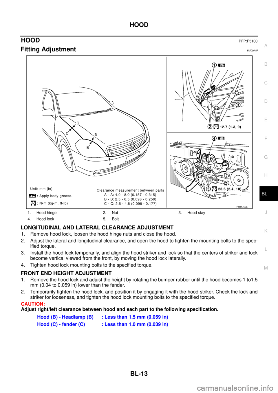
Fitting AdjustmentBIS000VP
LONGITUDINAL AND LATERAL CLEARANCE ADJUSTMENT
1. Remove hood lock, loosen the hood hinge nuts and close the hood.
2. Adjust the lateral and longitudinal clearance, and open the hood to tighten the mounting bolts to the spec-
ified torque.
3. Install the hood lock temporarily, and align the hood striker and lock so that the centers of striker and lock
become vertical viewed from the front, by moving the hood lock laterally.
4. Tighten hood lock mounting bolts to the specified torque.
FRONT END HEIGHT ADJUSTMENT
1. Remove the hood lock and adjust the height by rotating the bumper rubber until the hood becomes 1 to1.5
mm (0.04 to 0.059 in) lower than the fender.
2. Temporarily tighten the hood lock, and position it by engaging it with the hood striker. Check the lock and
striker for looseness, and tighten the hood lock mounting bolts to the specified torque.
CAUTION:
Adjust right/left clearance between hood and each part to the following specification.
1. Hood hinge 2. Nut 3. Hood stay
4. Hood lock 5. Bolt
PIIB1752E
Hood (B) - Headlamp (B) : Less than 1.5 mm (0.059 in)
Hood (C) - fender (C) : Less than 1.0 mm (0.039 in)
Page 672 of 3502

BL-14
HOOD
SURFACE HEIGHT ADJUSTMENT
1. Remove hood lock, and adjust the surface height difference of hood, fender and headlamp according to
the fitting standard dimension, by rotating RH and LH bumper rubbers.
2. Install hood lock temporarily, and move hood lock laterally until the centers of striker and lock become ver-
tical when viewed from the front.
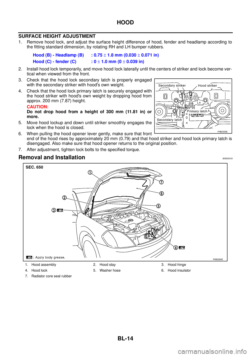
3. Check that the hood lock secondary latch is properly engaged
with the secondary striker with hood's own weight.
4. Check that the hood lock primary latch is securely engaged with
the hood striker with hood's own weight by dropping hood from
approx. 200 mm (7.87) height.
CAUTION:
Do not drop hood from a height of 300 mm (11.81 in) or
more.
5. Move hood lockup and down until striker smoothly engages the
lock when the hood is closed.
6. When pulling the hood opener lever gently, make sure that front
end of the hood rises by approximately 20 mm (0.79) and that hood striker and hood lock primary latch is
disengaged. Also make sure that hood opener returns to the original position.
7. After adjustment, tighten lock bolts to the specified torque.
Removal and InstallationBIS000VQ
Hood (B) - Headlamp (B) : 0.75 ± 1.8 mm (0.030 ± 0.071 in)
Hood (C) - fender (C) : 0 ± 1.0 mm (0 ± 0.039 in)
PIIB0259E
1. Hood assembly 2. Hood stay 3. Hood hinge
4. Hood lock 5. Washer hose 6. Hood insulator
7. Radiator core seal rubber
PIIB0260E
Page 673 of 3502
HOOD
BL-15
C
D
E
F
G
H
J
K
L
MA
B
BL
REMOVAL
Hood Assembly
1. Support the hood striker with a proper material to prevent it from
falling.
WARNING:
Body injury may occur if no supporting rod is holding the
hood open when removing the hood stay.
2. Disconnect washer hose at the connecting point.
3. Remove the hood stays from the stud balls on the body side.
4. Remove hinge nuts on hood and remove hood assembly.
CAUTION:
Operate with two workers, because of its heavy weight.
INSTALLATION
�Install in the reverse order of removal.
�Apply Anti-Corrosion or equivalent to the attaching portion of hood hinge, hood ledge, and hood assembly.
�After installing, perform hood fitting adjustment. Refer to BL-13, "Fitting Adjustment" .
PIIB0261E
: 12.7 N·m (1.3 kg-m, 9 ft-lb)
PIIB0262E
Page 674 of 3502

BL-16
HOOD
Removal and Installation of Hood Lock ControlBIS000VR
REMOVAL
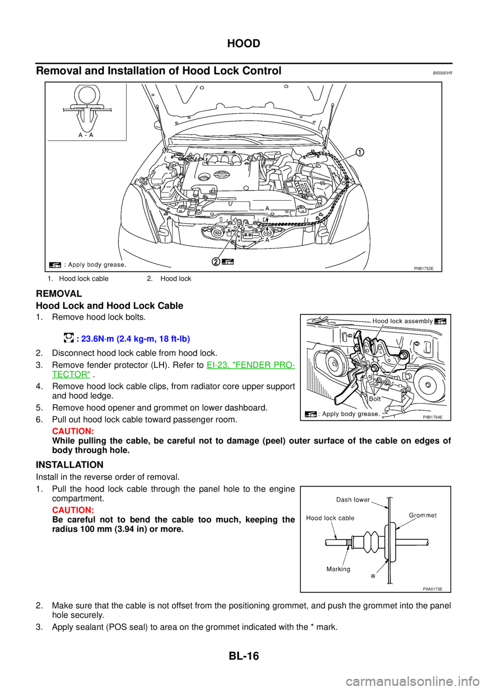
Hood Lock and Hood Lock Cable
1. Remove hood lock bolts.
2. Disconnect hood lock cable from hood lock.
3. Remove fender protector (LH). Refer to EI-23, "
FENDER PRO-
TECTOR" .
4. Remove hood lock cable clips, from radiator core upper support
and hood ledge.
5. Remove hood opener and grommet on lower dashboard.
6. Pull out hood lock cable toward passenger room.
CAUTION:
While pulling the cable, be careful not to damage (peel) outer surface of the cable on edges of
body through hole.
INSTALLATION
Install in the reverse order of removal.
1. Pull the hood lock cable through the panel hole to the engine
compartment.
CAUTION:
Be careful not to bend the cable too much, keeping the
radius 100 mm (3.94 in) or more.
2. Make sure that the cable is not offset from the positioning grommet, and push the grommet into the panel
hole securely.
3. Apply sealant (POS seal) to area on the grommet indicated with the * mark.
1. Hood lock cable 2. Hood lock
PIIB1753E
: 23.6N·m (2.4 kg-m, 18 ft-lb)
PIIB1754E
PIIA0173E
Page 675 of 3502

HOOD
BL-17
C
D
E
F
G
H
J
K
L
MA
B
BL
4. Install cable securely to the lock.
5. After installing, check hood lock adjustment and hood opener
operation.
6. After installing, perform hood fitting adjustment. Refer to BL-13,
"Fitting Adjustment" .
Hood Lock Control InspectionBIS000VS
CAUTION:
If the hood lock cable is bent or deformed, replace it.
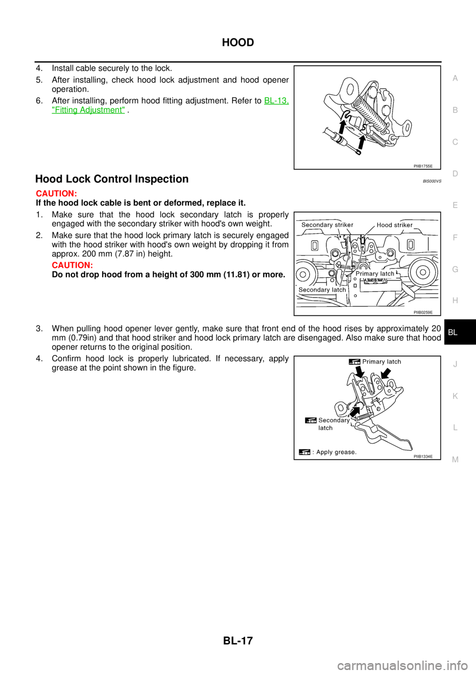
1. Make sure that the hood lock secondary latch is properly
engaged with the secondary striker with hood's own weight.
2. Make sure that the hood lock primary latch is securely engaged
with the hood striker with hood's own weight by dropping it from
approx. 200 mm (7.87 in) height.
CAUTION:
Do not drop hood from a height of 300 mm (11.81) or more.
3. When pulling hood opener lever gently, make sure that front end of the hood rises by approximately 20
mm (0.79in) and that hood striker and hood lock primary latch are disengaged. Also make sure that hood
opener returns to the original position.
4. Confirm hood lock is properly lubricated. If necessary, apply
grease at the point shown in the figure.
PIIB1755E
PIIB0259E
PIIB1334E
Page 677 of 3502
RADIATOR CORE SUPPORT
BL-19
C
D
E
F
G
H
J
K
L
MA
B
BL
12. Remove radiator core support upper, side, and center as a single piece. Remove mounting bolts and nuts
with power tool.
13. After removing radiator core support upper, side, and center as a single piece, separate the following
parts.
�Horns (High/Low)
�Air guides (LH/RH)
�Radiator core support side (LH/RH)
�Radiator core upper support
�Radiator core support center
INSTALLATION
Install in the reverse order of removal.
CAUTION:
After installing, check the hood adjustment and hood opener operation. Refer to BL-17, "
Hood Lock
Control Inspection" .