Page 1 of 3502

MODEL J31 SERIES
2006 NISSAN EUROPE S.A.S.
All rights reserved. No part of this Electronic Service Manual may be reproduced or stored in a retrieval system, or transmitted in any
form, or by any means, electronic, mechanical, photocopying, recording or otherwise, without the prior written permission of Nissan
Europe S.A.S., Paris, France.
A GENERAL INFORMATION
B ENGINE
C TRANSMISSION/TRANSAXLE
D DRIVELINE/AXLE
E SUSPENSION
F BRAKES
G STEERING H RESTRAINTS
I BODY
J AIR CONDITIONER
K ELECTRICAL
L MAINTENANCE
M INDEXGI General Information
EM Engine Mechanical
LU Engine Lubrication System
CO Engine Cooling System
EC Engine Control System
FL Fuel System
EX Exhaust System
ACC Accelerator Control System
AT Automatic Transmission
CVT CVT
FAX Front Axle
RAX Rear Axle
FSU Front Suspension
RSU Rear Suspension
WT Road Wheels & Tires
BR Brake System
PB Parking Brake System
BRC Brake Control System
PS Power Steering System
SB Seat Belts
SRS Supplemental Restraint System (SRS)
BL Body, Lock & Security System
GW Glasses, Window System & Mirrors
RF Roof
EI Exterior & Interior
IP Instrument Panel
SE Seat
ATC Automatic Air Conditioner
SC Starting & Charging System
LT Lighting System
DI Driver Information System
WW Wiper, Washer & Horn
BCS Body Control System
LAN LAN System
AV Audio, Visual & Telephone System
ACS Auto Cruise Control System
PG Power Supply, Ground & Circuit Elements
MA Maintenance
IDX Alphabetical Index
QUICK REFERENCE INDEX
A
B
C
D
E
F
G
H
I
J
K
L
M
Page 485 of 3502
A/C CONTROLLER
ATC-107
C
D
E
F
G
H
I
K
L
MA
B
AT C
A/C CONTROLLERPFP:27500
Removal and Installation of A/C and AV SwitchBJS000H4
REMOVAL
Refer to AV- 1 5 , "Removal and Installation of Audio Unit" (Integrated display system) or AV- 3 4 , "Removal and
Installation of Audio Unit" (Integrated color display system).
INSTALLATION
Installation is basically the reverse order of removal.
Page 486 of 3502
ATC-108
AUTO AMP
AUTO AMPPFP:27760
Removal and Installation of Unified Meter and A/C Amp.BJS000H6
REMOVAL
Refer to AV- 1 5 , "Removal and Installation of Audio Unit" (Integrated display system) or AV- 3 4 , "Removal and
Installation of Audio Unit" (Integrated color display system).
INSTALLATION
Installation is basically the reverse order of removal.
Page 529 of 3502

AV-1
AUDIO, VISUAL, NAVIGATION & TELEPHONE SYS-
TEM
K ELECTRICAL
CONTENTS
C
D
E
F
G
H
I
J
L
M
SECTION AV
A
B
AV
AUDIO, VISUAL, NAVIGATION & TELEPHONE SYSTEM
PRECAUTIONS .......................................................... 3
Precautions for Supplemental Restraint System
(SRS) “AIR BAG” and “SEAT BELT PRE-TEN-
SIONER” .................................................................. 3
AUDIO (WITH INTEGRATED DISPLAY SYSTEM) ..... 4
System Description .................................................. 4
AUDIO SYSTEM ................................................... 4
Component Parts Location ....................................... 5
Schematic ................................................................ 6
Wiring Diagram — AUDIO — ................................... 7
Terminals and Reference Value for Audio Unit ........ 11
Terminals and Reference Value for A/C and AV
Switch ..................................................................... 12
Terminals and Reference Value for Display Unit .... 12
A/C and AV Switch Self-Diagnosis Function .......... 13
STARTING THE SELF-DIAGNOSIS MODE ....... 13
DIAGNOSIS FUNCTION ..................................... 13
EXITING THE SELF-DIAGNOSIS MODE ........... 13
Symptom Chart ...................................................... 14
Removal and Installation of Audio Unit .................. 15
REMOVAL ........................................................... 15
INSTALLATION ................................................... 16
Removal and Installation of Front Door Speaker ... 16
REMOVAL ........................................................... 16
INSTALLATION ................................................... 16
Removal and Installation of Rear Door Speaker .... 17
REMOVAL ........................................................... 17
INSTALLATION ................................................... 17
Removal and Installation of Tweeter ...................... 17
REMOVAL ........................................................... 17
INSTALLATION ................................................... 17
AUDIO (WITH INTEGRATED COLOR DISPLAY
SYSTEM) .................................................................. 18
System Description ................................................ 18
AUDIO SYSTEM ................................................. 18
Component Parts Location ..................................... 19
Schematic .............................................................. 20
Wiring Diagram — AUDIO — ................................. 21
Terminals and Reference Value for Audio Unit ....... 28
Terminals and Reference Value for CD Auto Changer .................................................................. 30
Terminals and Reference Value for A/C and AV
Switch ..................................................................... 31
Terminals and Reference Value for Display Control
Unit ......................................................................... 31
A/C and AV Switch Self-Diagnosis Function .......... 32
STARTING THE SELF-DIAGNOSIS MODE ....... 32
DIAGNOSIS FUNCTION ..................................... 32
EXITING THE SELF-DIAGNOSIS MODE ........... 32
Symptom Chart ....................................................... 33
Removal and Installation of Audio Unit ................... 34
REMOVAL ........................................................... 34
INSTALLATION ................................................... 35
Removal and Installation of Rear Audio Control
Switch ..................................................................... 36
REMOVAL ........................................................... 36
INSTALLATION ................................................... 36
Removal and Installation of CD Auto Changer ....... 36
REMOVAL ........................................................... 36
INSTALLATION ................................................... 36
Removal and Installation of Front Door Speaker .... 37
REMOVAL ........................................................... 37
INSTALLATION ................................................... 37
Removal and Installation of Rear Door Speaker .... 37
REMOVAL ........................................................... 37
INSTALLATION ................................................... 37
Removal and Installation of Tweeter ...................... 37
REMOVAL ........................................................... 37
INSTALLATION ................................................... 37
AUDIO ANTENNA .................................................... 38
Wiring Diagram — W/ANT — ................................. 38
Location of Antenna ................................................ 39
Window Antenna Repair ......................................... 39
CHECK ELEMENT .............................................. 39
Removal and Installation of Antenna Amp. ............ 40
REMOVAL ........................................................... 40
INSTALLATION ................................................... 40
INTEGRATED DISPLAY SYSTEM ........................... 41
System Description ................................................. 41
INTEGRATED DISPLAY SYSTEM ...................... 41
Page 532 of 3502
AV-4
AUDIO (WITH INTEGRATED DISPLAY SYSTEM)
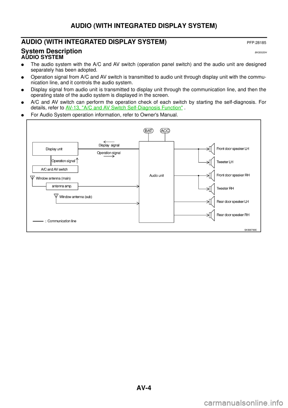
AUDIO (WITH INTEGRATED DISPLAY SYSTEM)PFP:28185
System DescriptionBKS0020H
AUDIO SYSTEM
�The audio system with the A/C and AV switch (operation panel switch) and the audio unit are designed
separately has been adopted.
�Operation signal from A/C and AV switch is transmitted to audio unit through display unit with the commu-
nication line, and it controls the audio system.
�Display signal from audio unit is transmitted to display unit through the communication line, and then the
operating state of the audio system is displayed in the screen.
�A/C and AV switch can perform the operation check of each switch by starting the self-diagnosis. For
details, refer to AV- 1 3 , "
A/C and AV Switch Self-Diagnosis Function" .
�For Audio System operation information, refer to Owner's Manual.
SKIB8799E
Page 533 of 3502
AUDIO (WITH INTEGRATED DISPLAY SYSTEM)
AV-5
C
D
E
F
G
H
I
J
L
MA
B
AV
Component Parts LocationBKS0020I
SKIB8800E
Page 534 of 3502
AV-6
AUDIO (WITH INTEGRATED DISPLAY SYSTEM)
SchematicBKS0020J
TKWM4654E
Page 535 of 3502
AUDIO (WITH INTEGRATED DISPLAY SYSTEM)
AV-7
C
D
E
F
G
H
I
J
L
MA
B
AV
Wiring Diagram — AUDIO —BKS0020K
TKWM4655E

 or")

AV-5
C
D
E
F
G
H
I
J
L
MA
B
AV
Component Parts LocationBKS0020I
SKIB8800E")

SchematicBKS0020J
TKWM4654E")

AV-7
C
D
E
F
G
H
I
J
L
MA
B
AV
Wiring Diagram — AUDIO —BKS0020K
TKWM4655E")