Page 788 of 3502
BL-130
REAR DOOR LOCK
9. While pulling outside handle, slide toward front of vehicle to
remove outside handle bracket.
10. Reach to separate outside handle cable connection.
11. Remove the TORX bolts (T30) of door lock assembly.
12. Disconnect the door lock actuator connector and remove door lock assembly.
INSTALLATION
Note the following, and install in the reverse order of removal.
CAUTION:
�To install each rod, be sure to rotate the rod holder until a click is felt.
�Before installing door lock assembly, apply Anti-Corrosion Wax M-97 Super or equivalent onto
mounting seat on the body.
�Place the outside handle bracket cable on the rear of door lock assembly before installing.
PIIB0580E
MIIB0134E
MIIB0132E
Page 791 of 3502

TRUNK LID
BL-133
C
D
E
F
G
H
J
K
L
MA
B
BL
3. Remove trunk lid stay.
WARNING:
Body injury may occur if no supporting rod is holding the
trunk lid open when removing the damper stay.
4. Remove the trunk lid hinge mounting bolts, and remove the
trunk lid assembly.
CAUTION:
Operate with two workers, because of its heavy weight.
INSTALLATION
Install in the reverse order of removal.
CAUTION:
�After installing, apply touch-up paint (the body color) onto the head of the hinge mounting bolts.
�After installing, check the trunk lid adjustment. Refer to BL-131, "Fitting Adjustment" .
Trunk Lid Stay Removal and InstallationBIS000Y2
REMOVAL
1. Insert flat-bladed screwdriver into the gap and remove holder.
2. Remove trunk lid stay on the trunk lid.
3. Remove the stud bolts, and trunk lid stay.
WARNING:
Body injury may occur if no supporting rod is holding the trunk
lid open when removing the damper stay.
INSTALLATION
1. Install in the reverse order of removal.
2. After installing, check the operation.
PIIB0290E
SIIA1561E
PIIB0290E
Page 792 of 3502

BL-134
TRUNK LID
Removal and Installation of Trunk Lid Lock BIS000Y3
REMOVAL
1. Remove the trunk lid finisher. Refer to EI-58, "TRUNK ROOM
TRIM & TRUNK LID FINISHER" .
2. Disconnect the emergency handle and trunk lid opener cable
from the clip.
3. After removing the harness connector, remove the mounting
bolts, and remove the trunk lid lock.
INSTALLATION
1. Install in the reverse order of removal.
2. After installing, close the trunk lid. Perform the lock and surface height adjustment. Refer to BL-131, "
Fit-
ting Adjustment" .
3. After installing, check the operation.
Trunk Lid Striker Removal and InstallationBIS000Y4
REMOVAL
1. Remove the trunk rear plate and trunk rear finisher. Refer to EI-
58, "Removal and Installation for Trunk Room Trim" .
2. Remove the mounting bolts, and remove the striker from the
trunk lock support.
INSTALLATION
1. Install in the reverse order of removal.
2. After installing, close the trunk lid. Perform the lock and surface height adjustment. Refer to BL-131, "
Fit-
ting Adjustment" .
3. After installing, check the operation. : 5.8 N·m (0.59 kg-m, 51 in-lb)
PIIB1228E
: 13.5 N·m (1.4 kg-m, 10 ft-lb)
PIIB1229E
Page 818 of 3502
BL-160
NATS(NISSAN ANTI-THEFT SYSTEM)
4. CHECK BCM FUNCTION
1. Connect security indicator lamp connector.
2. Disconnect BCM connector.
3. Check voltage between BCM connector M3 terminal 23 (L/B)
and ground.
OK or NG
OK >> BCM is malfunctioning.
�Replace BCM.
�Perform initialization with CONSULT-II.
�For initialization, refer to “CONSULT-II Operation
Manual NATS”.
NG >> Check the following.
�Harness for open or short between security indicator lamp and BCM.
�Indicator lamp condition
Removal and Installation NATS Antenna Amp.BIS000YT
REMOVAL
CAUTION:
Before servicing SRS, turn ignition switch OFF, disconnect both battery cables and wait at least 3 min-
utes.
1. Remove the steering column cover. Refer to IP-10, "
Component Parts Location" .
2. Disconnect the NATS antenna amp. connector, remove the
screw and NATS antenna amp.
INSTALLATION
Install in the reverse order of removal.23 (L/B) – Ground : Battery voltage
PIIA6150E
PIIA6064E
Page 826 of 3502
BR-8
BRAKE PEDAL
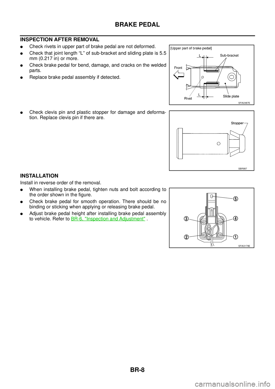
INSPECTION AFTER REMOVAL
�Check rivets in upper part of brake pedal are not deformed.
�Check that joint length “L” of sub-bracket and sliding plate is 5.5
mm (0.217 in) or more.
�Check brake pedal for bend, damage, and cracks on the welded
parts.
�Replace brake pedal assembly if detected.
�Check clevis pin and plastic stopper for damage and deforma-
tion. Replace clevis pin if there are.
INSTALLATION
Install in reverse order of the removal.
�When installing brake pedal, tighten nuts and bolt according to
the order shown in the figure.
�Check brake pedal for smooth operation. There should be no
binding or sticking when applying or releasing brake pedal.
�Adjust brake pedal height after installing brake pedal assembly
to vehicle. Refer to BR-6, "
Inspection and Adjustment" .
SFIA2487E
SBR997
SFIA3179E
Page 832 of 3502

BR-14
BRAKE MASTER CYLINDER
BRAKE MASTER CYLINDERPFP:46010
On-Board InspectionBFS000BP
LEAK INSPECTION
�Check for leaking in a master cylinder installation surface, a reservoir tank installation surface, and brake
tube connections.
Removal and InstallationBFS000BQ
CAUTION:
Be careful not to splash brake fluid on painted areas; it way cause paint damage. If brake fluid is
splashed on painted surfaces of body, immediately wipe it off and them wash it away with water imme-
diately.
REMOVAL
1. Drain brake fluid. Refer to BR-9, "Drain and Refill" .
2. Remove brake fluid level switch harness connector.
3. Using a flare nut wrench, remove brake tubes from master cylinder assembly.
4. Remove master cylinder mounting nuts, remove master cylinder assembly from vehicle.
INSTALLATION
CAUTION:
�Refill with new brake fluid “DOT 3 or DOT 4”.
�Do not reuse drained brake fluid.
1. Install in the reverse order of removal and tighten nuts to the specified torque. Refer to BR-22, "
COMPO-
NENTS" .
Models with VDC
�Apply silicon grease in inner kit to O-ring and it's surrounding
areas and to booster side inner wall.
CAUTION:
�Do not damage the sliding surface of primary piston rod
and do not allow foreign materials on it's surface.
�Do not reuse the O-ring.
2. Install brake tube to master cylinder assembly and temporarily
tighten flare nut by hand.
3. Tighten brake tube flare nut to the specified torque using a flare
nut torque wrench. Refer to BR-11, "
Hydraulic Circuit" .
4. Install brake fluid level switch harness connector.
5. Refill with new brake fluid and bleed air. Refer to BR-10, "
Bleeding Brake System" .
SFIA1302E
Page 896 of 3502
![NISSAN TEANA 2003 Service Manual BRC-36
[ABS]
ACTUATOR AND ELECTRIC UNIT (ASSEMBLY)
REMOVAL
1. Disconnect ABS actuator and electric unit (control unit) connector.
2. Loosen brake tube flare nuts, then remove brake tubes from ABS ac](/manual-img/5/57392/w960_57392-895.png "NISSAN TEANA 2003 Service Manual BRC-36
[ABS]
ACTUATOR AND ELECTRIC UNIT (ASSEMBLY)
REMOVAL
1. Disconnect ABS actuator and electric unit (control unit) connector.
2. Loosen brake tube flare nuts, then remove brake tubes from ABS ac")
BRC-36
[ABS]
ACTUATOR AND ELECTRIC UNIT (ASSEMBLY)
REMOVAL
1. Disconnect ABS actuator and electric unit (control unit) connector.
2. Loosen brake tube flare nuts, then remove brake tubes from ABS actuator and electric unit (control unit).
3. Remove ABS actuator and electric unit (control unit) mounting bolts.
4. Remove ABS actuator and electric unit (control unit) from vehicle.
CAUTION:
Be careful of the following when removing ABS actuator and electric unit (control unit).
�If the part number on the part number label (pasted on actuator upper surface) is the same, ABS
actuator and electric unit (control unit) cannot be used on another vehicle.
If it is used on another vehicle, ABS warning lamp, may turn ON or ABS may not operate normally.
When replacing ABS actuator and electric unit (control unit), must use new service parts.
�Before servicing, disconnect both battery cables.
�To remove brake tube, use a flare nut torque wrench to prevent flare nuts and brake tube from
being damaged. To install, use a flare nut torque wrench (commercial service tool) and tighten
with the specified torque.
�Do not apply excessive impact to actuator, such as dropping it.
�Do not remove and install ABS actuator and electric unit (control unit) by holding harness.
INSTALLATION
Install is in the reverse order of the removal.
CAUTION:
Be careful of the following when installing ABS actuator and electric unit (control unit).
�Tighten the mounting bolts and nuts with the specified torque.
�After the work, bleed air from brake piping. Refer to BR-10, "Bleeding Brake System" .
�After installing body harness connector in the actuator, make sure connector is securely locked.
Page 949 of 3502
![NISSAN TEANA 2003 Service Manual ACTUATOR AND ELECTRIC UNIT (ASSEMBLY)
BRC-89
[VDC/TCS/ABS]
C
D
E
G
H
I
J
K
L
MA
B
BRC
REMOVAL
1. Disconnect ABS actuator and electric unit (control unit) connector.
2. Loosen brake tube flare nuts,](/manual-img/5/57392/w960_57392-948.png "NISSAN TEANA 2003 Service Manual ACTUATOR AND ELECTRIC UNIT (ASSEMBLY)
BRC-89
[VDC/TCS/ABS]
C
D
E
G
H
I
J
K
L
MA
B
BRC
REMOVAL
1. Disconnect ABS actuator and electric unit (control unit) connector.
2. Loosen brake tube flare nuts,")
ACTUATOR AND ELECTRIC UNIT (ASSEMBLY)
BRC-89
[VDC/TCS/ABS]
C
D
E
G
H
I
J
K
L
MA
B
BRC
REMOVAL
1. Disconnect ABS actuator and electric unit (control unit) connector.
2. Loosen brake tube flare nuts, then remove brake tubes from ABS actuator and electric unit (control unit).
3. Remove ABS actuator and electric unit (control unit) mounting nuts.
4. Remove ABS actuator and electric unit (control unit) from vehicle.
CAUTION:
Be careful of the following when removing ABS actuator and electric unit (control unit).
�If the part number on the part number label (pasted on actuator upper surface) is the same, ABS
actuator and electric unit (control unit) cannot be used on another vehicle.
If it is used on another vehicle, ABS warning lamp, SLIP indicator lamp and VDC OFF indicator
lamp may turn ON or VDC/TCS/ABS may not operate normally.
When replacing ABS actuator and electric unit (control unit), must use new service parts.
�Before servicing, disconnect battery cables.
�To remove brake tube, use a flare nut torque wrench to prevent flare nuts and brake tube from
being damaged. To install, use a flare nut torque wrench (commercial service tool) and tighten
with the specified torque.
�Do not apply excessive impact to actuator, such as dropping it.
�Do not remove and install ABS actuator and electric unit (control unit) by holding harness.
INSTALLATION
Install is in the reverse order of the removal.
CAUTION:
Be careful of the following when installing ABS actuator and electric unit (control unit).
�Tighten the mounting bolts and nuts with the specified torque.
�After the work, bleed air from brake piping. Refer to BR-10, "Bleeding Brake System" .
�After installing body harness connector in the actuator, make sure connector is securely locked
�When replacing ABS actuator and electric unit (control unit), calibrate Steering angle sensor neu-
tral position. Refer to BRC-40, "
Adjustment of Steering Angle Sensor Neutral Position" .


4. CHECK BCM FUNCTION
1. Connect security indicator lamp connector.
2. Disconnect BCM connector.
3. Check voltage between BCM connector M3 terminal 23 (L/B)
and")