Page 568 of 3502
AV-40
AUDIO ANTENNA
2. If an element is broken, no continuity will exist.
3. To locate a break, move probe along element. Tester needle will
swing abruptly when probe passes the broken point.
Removal and Installation of Antenna Amp.BKS0021X
REMOVAL
1. Remove headlining. Refer to EI-54, "HEADLINING" .
2. Remove screw and disconnect antenna feeder clip and antenna
connector, and then remove antenna amp.
INSTALLATION
Installation is the reverse order of removal.
SEL252I
SEL253I
SKIA6302E
Page 588 of 3502
AV-60
INTEGRATED DISPLAY SYSTEM
Removal and Installation of Display UnitBKS0022K
REMOVAL
1. Remove cluster lid D. Refer to IP-10, "INSTRUMENT PANEL ASSEMBLY" .
2. Remove screws (4), and remove display unit.
3. Remove screws (4) and nylon washers (4), and then remove
display finisher.
4. Remove screws (4), and remove bracket.
INSTALLATION
Installation is the reverse order of removal.
Removal and Installation of A/C and AV SwitchBKS0022L
REMOVAL
Remove A/C and AV switch integral with audio unit. Refer to AV- 1 5 , "Removal and Installation of Audio Unit" .
INSTALLATION
Installation is the reverse order of removal.
SKIA6307E
SKIA6779E
Page 590 of 3502

AV-62
INTEGRATED COLOR DISPLAY SYSTEM
Component DescriptionBKS0027K
DISPLAY CONTROL UNIT
�Display control unit draws a status of the audio system and air
conditioner system, a TRIP screen, a FUEL ECONOMY screen,
etc., and transmits the image signals to the display screen.
�It receives operation signals of audio system and air conditioner
system from A/C and AV switch, and transmits the operation sig-
nal of audio system to the audio unit through the communication
line and transmits the operation signal of air conditioner system
to the unified meter and A/C amp. through CAN communication.
�Display signal from audio unit is transmitted to display control
unit through the communication line, and then the operating
state of the audio system is displayed in the screen.
�Display signal from unified meter and A/C amp. is transmitted to
display control unit through the CAN communication, and then the operating state of the air conditioner
system is displayed in the screen.
DISPLAY
�Images on the display include RGB image and rear view image
displayed when setting the select lever to R range.
�Display control unit controls images on the display.
A/C AND AV SWITCH
�A/C and AV switch, an integrated combination of audio system
and air conditioner system switches, are adopted.
�Operation signal of audio system is transmitted to the audio unit
through display control unit with the communication line.
�Operation signal of air conditioner system is transmitted to uni-
fied meter and A/C amp. through display control unit with CAN
communication.
REAR VIEW CAMERA
�Rear view camera transmits rear view image signals to the dis-
play screen through the rear view camera control unit, when
reverse signal is input.
�The rear view image is a mirror image reversed left and right
that is the same as seeing rear side with a room mirror.
SKIB0800E
SKIB8808E
SKIB8808E
SKIB0802E
Page 591 of 3502
INTEGRATED COLOR DISPLAY SYSTEM
AV-63
C
D
E
F
G
H
I
J
L
MA
B
AV
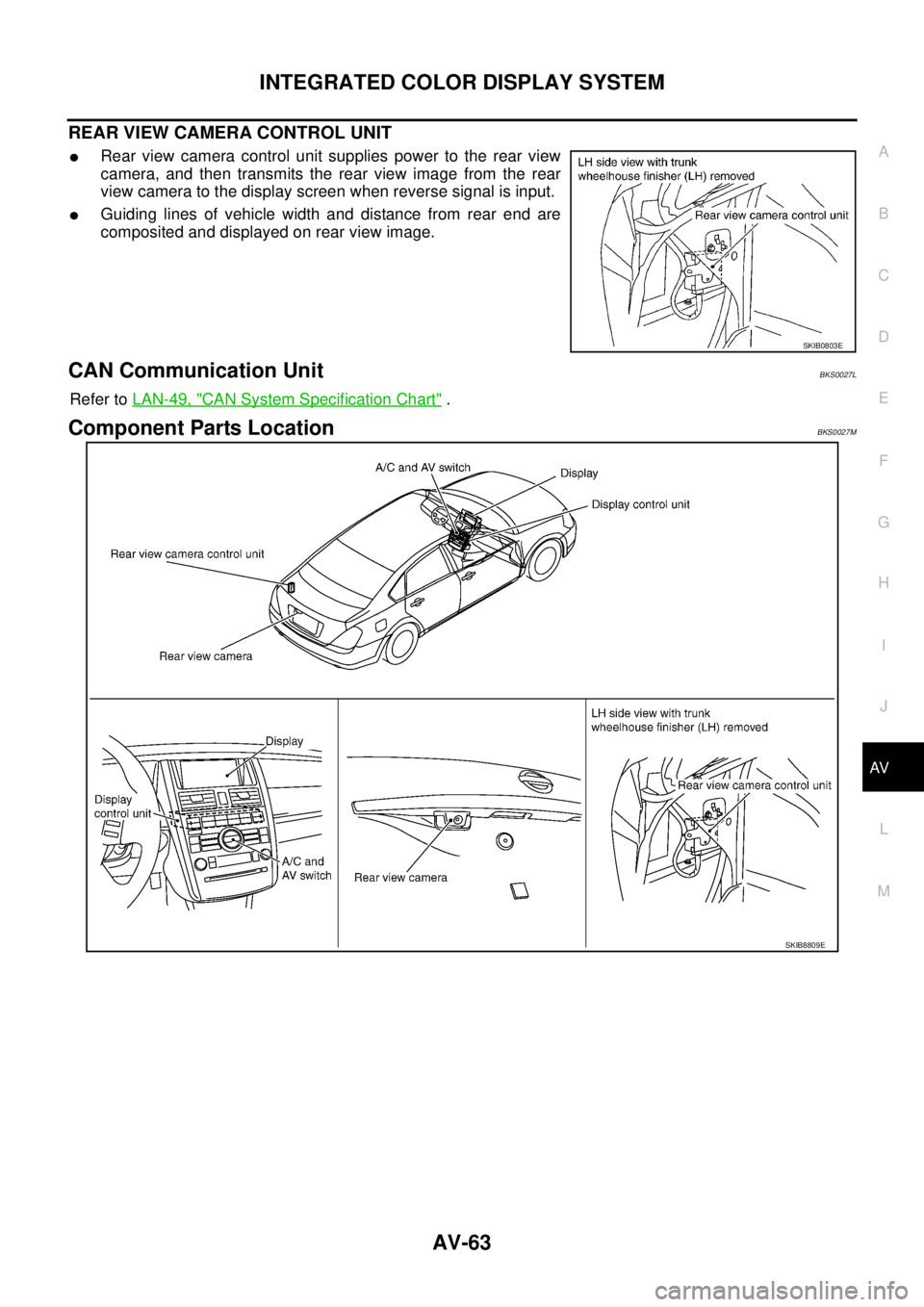
REAR VIEW CAMERA CONTROL UNIT
�Rear view camera control unit supplies power to the rear view
camera, and then transmits the rear view image from the rear
view camera to the display screen when reverse signal is input.
�Guiding lines of vehicle width and distance from rear end are
composited and displayed on rear view image.
CAN Communication UnitBKS0027L
Refer to LAN-49, "CAN System Specification Chart" .
Component Parts LocationBKS0027M
SKIB0803E
SKIB8809E
Page 605 of 3502

ItemSignal
input/
outputCondition
Reference valu")
INTEGRATED COLOR DISPLAY SYSTEM
AV-77
C
D
E
F
G
H
I
J
L
MA
B
AV
Terminals and Reference Value for Display Control UnitBKS0027R
Terminal
(Wire color)
ItemSignal
input/
outputCondition
Reference value
+–Ignition
switchOperation
1 (Y) Ground Battery power supply Input OFF — Battery voltage
2 (L/B) GroundPower supply
(Inverter) Output ON — Approx. 9 V
3 (B) Ground Ground — ON — Approx. 0 V
4 (L/Y) Ground Power supply (Signal) Output ON — Approx. 9 V
5 (P) Ground Ground (Inverter) — ON — Approx. 0 V
6 (G/W) Ground Reverse signal Input ONSelector lever in R position Approx. 12 V
Selector lever except in R
positionApprox. 0 V
7 (R/W) Ground Ground (Signal) — ON — Approx. 0 V
8 (BR/W) GroundCamera-connection
recognition signalInput ONConnected to rear view
camera control unit connec-
torApprox. 0 V
Not connected to rear view
camera control unit connec-
torApprox. 5 V
10 (V) Ground ACC power supply Input ACC — Battery voltage
12 (G) Ground Ignition signal Input ON — Battery voltage
14 (R/L) Ground Illumination signal Input ONLighting switch ON Approx. 12 V
Lighting switch OFF Approx. 0 V
16 (V/W) GroundVehicle speed signal
(8-pulse)Input ONWhen vehicle speed is
approx. 40 km/h (25 MPH)NOTE:
Maximum voltage may be 5 V
due to specifications (connected
units).
25 (L) — CAN-H — — — —
26 (P) — CAN-L — — — —
28 (BR) GroundCommunication
signal (+)Input/
OutputON —
29 — Shield — — — —
30 (Y) GroundCommunication
signal (–)Input/
OutputON —
PKIA1935E
SKIB7378E
SKIB7379E
Page 611 of 3502

ItemSignal
input/
outputCondition
Refer")
INTEGRATED COLOR DISPLAY SYSTEM
AV-83
C
D
E
F
G
H
I
J
L
MA
B
AV
Terminals and Reference Value for Rear View Camera Control UnitBKS0027U
Terminal
(Wire color)
ItemSignal
input/
outputCondition
Reference value
+–Ignition
switchOperation
1 (Y) Ground Battery power supply Input OFF — Battery voltage
2 (V) Ground ACC power supply Input ACC — Battery voltage
3 (B) Ground Ground — ON — Approx. 0 V
4 (G/W) Ground Reverse signal Input ONSelector lever in R position Approx. 12 V
Other than selector lever in
R positionApprox. 0 V
5 (BR/W) GroundCamera-connection
recognition signalOutput ON — Approx. 0 V
6 (O) —Data transmit/receive
signal—— — —
8 (P) Ground Camera power supply Output ONSet the selector lever in R
position, and then display
the rear view imageApprox. 6 V
9 — Shield — — — —
10 (W) GroundRear view image
signalInput ONSet the selector lever in R
position, and then display
the rear view image
11 — Shield — — — —
12 (BR) GroundRear view image
signalOutput ONSet the selector lever in R
position, and then display
the rear view image
SKIB3608E
SKIB3608E
Page 613 of 3502

INTEGRATED COLOR DISPLAY SYSTEM
AV-85
C
D
E
F
G
H
I
J
L
MA
B
AV
On Board Self-Diagnosis FunctionBKS0027W
DESCRIPTION
�Trouble diagnosis function of system has a self-diagnosis mode by automatic operation and a confirma-
tion mode by manual operation.
�Self-diagnosis mode checks for connections between the units constituting this system, analyzes each
individual unit at the same time, and displays the results on the display.
�Confirmation mode displays trouble diagnosis that require an operation and a judgment by a human
(auto-decision cannot be performed by the system), and an error history of system.
DIAGNOSIS ITEM
Mode Description
DCU Failure Diagnosis
�Display control unit diagnosis
�Analyzes connection between the display control unit and each unit, and operation of
each unit.
DCU
ConfirmationDCUDisplay DiagnosisColor tone and shading of the display control unit-generated image can be checked by
the display of a color bar and a gray scale.
Vehicle SignalDiagnosis of signals that are input to display control unit can be performed for speed sig-
nal, Light, IGN and Reverse.
History of ErrorMalfunctions that occurred in the past are displayed, along with the number of times each
has occurred.
Software Version Software version of each unit is displayed.
HVAC Self-diagnosis of air conditioner system is performed.
CAN Diagnosis The transmitting/receiving of CAN communication can be monitored.
Page 618 of 3502

AV-90
INTEGRATED COLOR DISPLAY SYSTEM
Vehicle Signal
A comparison check can be made of each actual vehicle signal and
the signals recognized by the display control unit.
History of Error
Diagnosis results of self-diagnosis depend on if any error occurred
during the time after selecting “DCU Failure Diagnosis” until self-
diagnosis results is displayed.
Meanwhile, when an error occurs before selecting “DCU Failure
Diagnosis”, and if an error does not occur until self-diagnosis results
is displayed, a diagnosis result is judged as normal.
Consequently, a diagnosis needs to be performed with “History of
Error” for the past error that is not available with self-diagnosis.
“History of Error” stores error occurrences up to 50, and errors after
the 51st are displayed as the 50th.
SKIB0835E
Diagnosis item Display Condition Remarks
Speed SignalON When vehicle speed is more than 0 km/h (0 MPH)
Changes in indication may be delayed.
This is normal. OFF When vehicle speed is 0 km/h (0 MPH)
— Ignition switch in ACC position
LightON Lighting switch ON
—
OFF Lighting switch OFF
IGNON Ignition switch ON
—
OFF Ignition switch ACC position
ReverseON Selector lever in R position
Changes in indication may be delayed.
This is normal. OFF Selector lever in any position other than R position
— Ignition switch in ACC position
SKIB8900E

, and remove displ")