Page 677 of 3502
RADIATOR CORE SUPPORT
BL-19
C
D
E
F
G
H
J
K
L
MA
B
BL
12. Remove radiator core support upper, side, and center as a single piece. Remove mounting bolts and nuts
with power tool.
13. After removing radiator core support upper, side, and center as a single piece, separate the following
parts.
�Horns (High/Low)
�Air guides (LH/RH)
�Radiator core support side (LH/RH)
�Radiator core upper support
�Radiator core support center
INSTALLATION
Install in the reverse order of removal.
CAUTION:
After installing, check the hood adjustment and hood opener operation. Refer to BL-17, "
Hood Lock
Control Inspection" .
Page 678 of 3502
BL-20
FRONT FENDER
FRONT FENDERPFP:63100
Removal and InstallationBIS000VU
REMOVAL
1. Remove the front bumper. Refer to EI-14, "FRONT BUMPER" .
2. Remove fender protector mounting clips and screws from out side. Refer to EI-23, "
FENDER PROTEC-
TOR" .
3. Remove center mud guard. Refer to EI-24, "
CENTER MUD GUARD" .
4. Remove bolts securing radiator core support side.
5. Remove hood hinge cover (rubber). Refer to EI-21, "
COWL TOP" .
6. Remove side turn signal lamp.
7. Remove bolts, and then remove front fender.
CAUTION:
While removing use a shop cloth to protect body from damaging.
INSTALLATION
Install in the reverse order of removal.
CAUTION:
�After installing, apply touch-up paint (the body color) onto the head of the front fender mounting
bolts.
�After installing, check front fender adjustment. Refer to BL-13, "Fitting Adjustment" and BL-119,
"Fitting Adjustment" .
1. Bolt 2. Front fender
PIIB0267E
Page 775 of 3502

INTELLIGENT KEY SYSTEM
BL-117
C
D
E
F
G
H
J
K
L
MA
B
BL
Check Headlamp FunctionBIS000XO
First perform the “SELF-DIAG RESULTS” in “BCM” with CONSULT-II, then perform the trouble diagnosis of
malfunction system indicated “SELF-DIAG RESULTS” of “BCM”. Refer to BCS-14, "
CAN Communication
Inspection Using CONSULT-II (Self-Diagnosis)" .
1. CHECK HEADLAMP OPERATION
Does headlamp come on when turning lighting switch “ON”?
YES or NO
YES >> Headlamp operation circuit is OK.
NO >> Check headlamp system. Refer to LT- 6 , "
HEADLAMP - XENON TYPE -" .
Removal and Installation of Intelligent Key UnitBIS001TH
REMOVAL
1. Remove the instrument driver lower panel. Refer to IP-10, "Component Parts Location" .
2. Disconnect Intelligent Key unit connector, remove screw and
Intelligent Key unit.
INSTALLATION
Install in the reverse order of removal.
Intelligent Key Battery ReplacementBIS001TI
DISASSEMBLY AND ASSEMBLY OF INTELLIGENT KEY
1. Release the lock knob at the back of the Intelligent Key and remove the mechanical key.
2. Insert a flat-blade screwdriver (A) wrapped with a close into the
slit of the corner and twist it to separate the upper part from the
lower part.
CAUTION:
�Be careful not to touch the circuit board or battery termi-
nal.
�The key fob is water-resistant. However, if it does get wet,
immediately wipe it dry.
3. Replace the battery with new one.
4. Align the tips of the upper and lower parts, and then push them
together until it is securely closed.
CAUTION:
�When replacing battery, be sure to keep dirt, grease, and
other foreign materials off the electrode contact area.
�After replacing the battery, check to make sure all Intelli-
gent Key functions work normally.
PIIB0276E
PIIB6221E
PIIB6222E
Page 778 of 3502

BL-120
DOOR
STRIKER ADJUSTMENT
Adjust the striker so that it becomes parallel with the lock insertion
direction.
Removal and Installation of Front DoorBIS000XS
CAUTION:
�When removing and installing the front door assembly, support the door with a jack and cloth to
protect the door and body.
�When removing and installing front door assembly, be sure to perform the fitting adjustment Refer
to BL-119, "
Fitting Adjustment" .
�Operate with two workers, because of its heavy weight.
�Check the hinge rotating part for poor lubrication. If necessary, apply “body grease”.
�After installing, check operation.
REMOVAL
1. Disconnect the front door harness connector.
2. Remove the mounting bolts of the check link on the vehicle.
3. Remove the door-side hinge mounting nuts, and remove the
door assembly.
INSTALLATION
Install in the reverse order of removal.
Removal and Installation of Rear DoorBIS000XT
CAUTION:
�When removing and installing the rear door assembly, support the door with a jack and cloth to
protect the door and body.
�When removing and installing rear door assembly, be sure to perform the fitting adjustment Refer
to BL-119, "
Fitting Adjustment" . : 16.7 N·m (1.7 kg-m, 12 ft-lb)
PIIB1226E
: 14.7 N·m (1.5 kg-m, 11 ft-lb)
PIIB1227E
: 24.5 N·m (2.5 kg-m, 18 ft-lb)
PIIB0279E
Page 779 of 3502
DOOR
BL-121
C
D
E
F
G
H
J
K
L
MA
B
BL
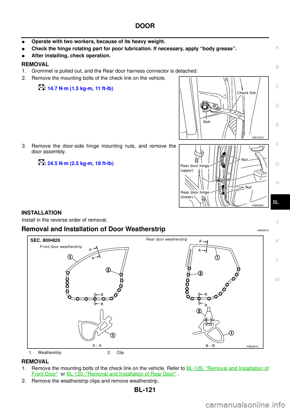
�Operate with two workers, because of its heavy weight.
�Check the hinge rotating part for poor lubrication. If necessary, apply “body grease”.
�After installing, check operation.
REMOVAL
1. Grommet is pulled out, and the Rear door harness connector is detached.
2. Remove the mounting bolts of the check link on the vehicle.
3. Remove the door-side hinge mounting nuts, and remove the
door assembly.
INSTALLATION
Install in the reverse order of removal.
Removal and Installation of Door WeatherstripBIS000XU
REMOVAL
1. Remove the mounting bolts of the check link on the vehicle. Refer to BL-120, "Removal and Installation of
Front Door" or BL-120, "Removal and Installation of Rear Door" .
2. Remove the weatherstrip clips and remove weatherstrip.: 14.7 N·m (1.5 kg-m, 11 ft-lb)
PIIB1227E
: 24.5 N·m (2.5 kg-m, 18 ft-lb)
PIIB0280E
1. Weatherstrip 2. Clip
PIIB0281E
Page 780 of 3502
BL-122
DOOR
INSTALLATION
Install in the reverse order of removal.
Page 784 of 3502
BL-126
FRONT DOOR LOCK
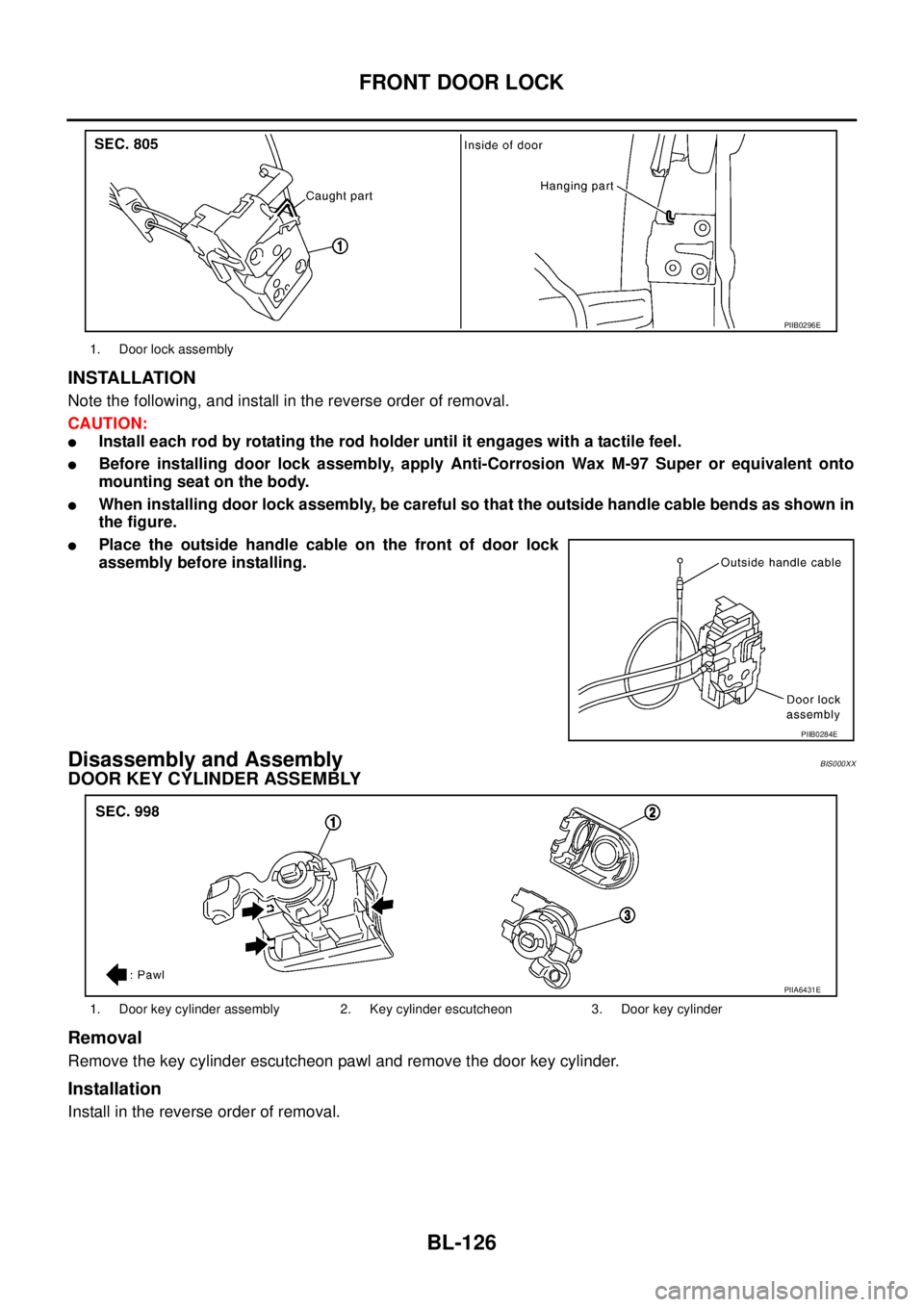
INSTALLATION
Note the following, and install in the reverse order of removal.
CAUTION:
�Install each rod by rotating the rod holder until it engages with a tactile feel.
�Before installing door lock assembly, apply Anti-Corrosion Wax M-97 Super or equivalent onto
mounting seat on the body.
�When installing door lock assembly, be careful so that the outside handle cable bends as shown in
the figure.
�Place the outside handle cable on the front of door lock
assembly before installing.
Disassembly and AssemblyBIS000XX
DOOR KEY CYLINDER ASSEMBLY
Removal
Remove the key cylinder escutcheon pawl and remove the door key cylinder.
Installation
Install in the reverse order of removal.
1. Door lock assembly
PIIB0296E
PIIB0284E
1. Door key cylinder assembly 2. Key cylinder escutcheon 3. Door key cylinder
PIIA6431E
Page 785 of 3502
FRONT DOOR LOCK
BL-127
C
D
E
F
G
H
J
K
L
MA
B
BL
OUTSIDE HANDLE
Removal
1. Remove handle cover screws.
2. Remove handle cover, and then remove door antenna. (Vehicles with intelligent key systems only)
Installation
Install in the reverse order of removal.
1. Outside handle 2. Screw 3. Handle cover
4. Door request switch 5. Pawl 6. Door antenna
PIIB0285E