INTAKE MANIFOLD COLLECTOR
EM-135
[VQ]
C
D
E
F
G
H
I
J
K
L
MA
EM
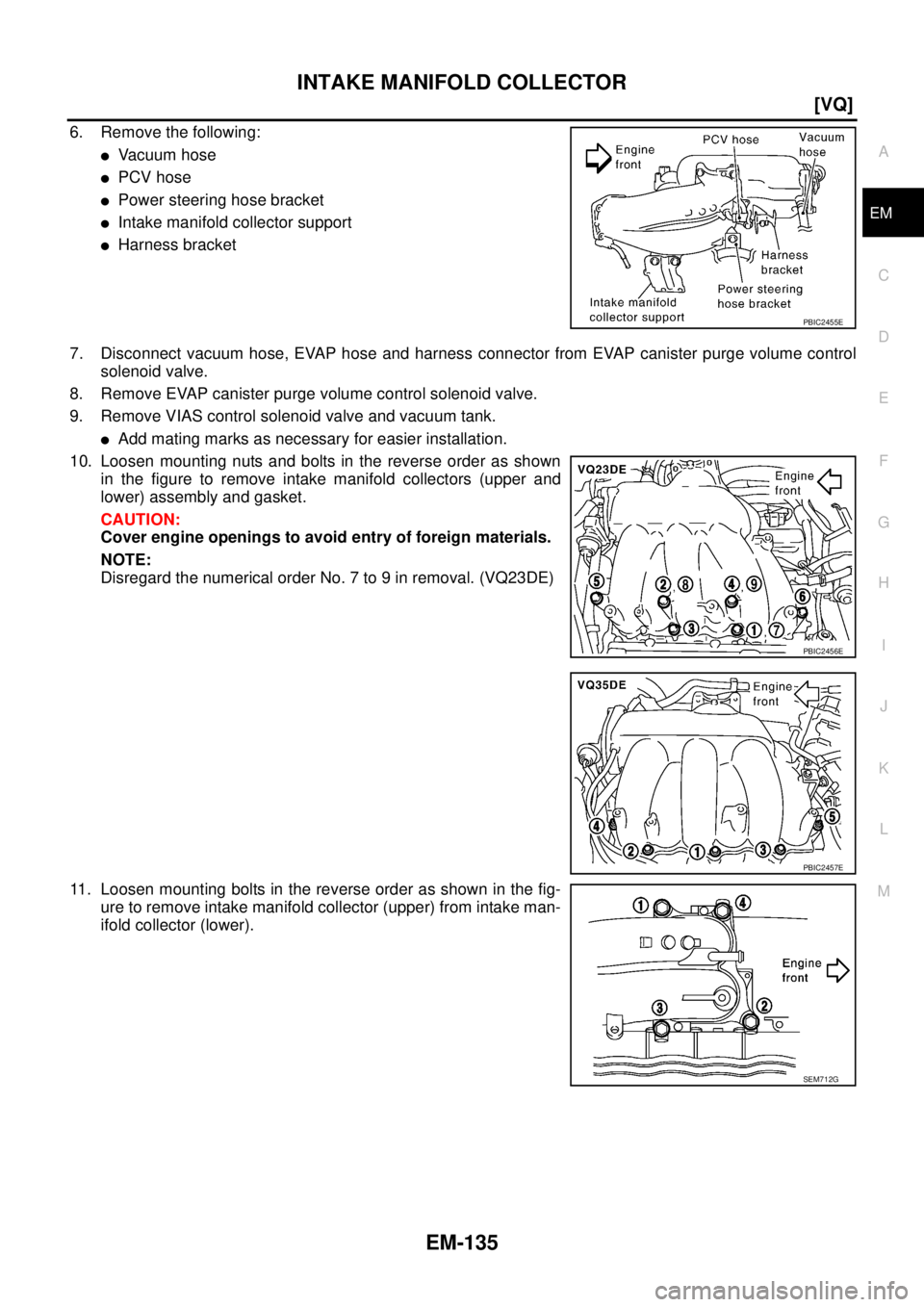
6. Remove the following:
�Va c u u m h o s e
�PCV hose
�Power steering hose bracket
�Intake manifold collector support
�Harness bracket
7. Disconnect vacuum hose, EVAP hose and harness connector from EVAP canister purge volume control
solenoid valve.
8. Remove EVAP canister purge volume control solenoid valve.
9. Remove VIAS control solenoid valve and vacuum tank.
�Add mating marks as necessary for easier installation.
10. Loosen mounting nuts and bolts in the reverse order as shown
in the figure to remove intake manifold collectors (upper and
lower) assembly and gasket.
CAUTION:
Cover engine openings to avoid entry of foreign materials.
NOTE:
Disregard the numerical order No. 7 to 9 in removal. (VQ23DE)
11. Loosen mounting bolts in the reverse order as shown in the fig-
ure to remove intake manifold collector (upper) from intake man-
ifold collector (lower).
PBIC2455E
PBIC2456E
PBIC2457E
SEM712G
FUEL SYSTEM
FL-3
C
D
E
F
G
H
I
J
K
L
MA
FL
FUEL SYSTEMPFP:17503
Checking Fuel LinesBBS005AE
Inspect fuel lines, fuel filler cap and fuel tank for improper attach-
ment, leaks, cracks, damage, loose connections, chafing or deterio-
ration.
If necessary, repair or replace damaged parts.
General PrecautionsBBS005AF
WARNING:
When replacing fuel line parts, be sure to observe the following.
�Put a “CAUTION: FLAMMABLE” sign in the workshop.
�Be sure to work in a well ventilated area and furnish workshop with a CO2 fire extinguisher.
�Do not smoke while servicing fuel system. Keep open flames and sparks away from the work area.
�Put drained fuel in an explosion-proof container and put the lid on securely. Keep the container in
safe area.
CAUTION:
�Use gasoline required by the regulations for octane number. Refer to GI-6, "Precautions for Fuel" .
�Before removing fuel line parts, perform the following procedures:
–Release fuel pressure from the fuel lines. Refer to EC-49, "FUEL PRESSURE RELEASE"
(QR20DE), or EC-392, "FUEL PRESSURE RELEASE" (VQ23DE and VQ35DE).
–Disconnect the battery cable from negative terminal.
�Always replace clamps with new ones.
�Do not kink or twist tubes when they are being installed.
�Perform work on level place.
�Do not tighten hose clamps excessively to avoid damaging hoses.
�After connecting fuel tube quick connectors, make sure
quick connectors are secure.
Ensure that connector and resin tube do not contact any
adjacent parts.
�After installing tubes, make sure there is no fuel leakage at
connections in the following steps.
–Apply fuel pressure to fuel lines with turning ignition switch
“ON” (with engine stopped). Then check for fuel leaks at
connections.
–Start engine and rev it up and check for fuel leaks at con-
nections.
�Use only a genuine NISSAN fuel filler cap as a replacement.
If an incorrect fuel filler cap is used, the “MIL” may come
on.
�For servicing “Evaporative Emission System” parts, refer to
EC-27, "
EVAPORATIVE EMISSION SYSTEM" (QR20DE), or
EC-366, "
EVAPORATIVE EMISSION SYSTEM" (VQ23DE
and VQ35DE).
SMA803A
SBIA0504E