Page 1 of 3502

MODEL J31 SERIES
2006 NISSAN EUROPE S.A.S.
All rights reserved. No part of this Electronic Service Manual may be reproduced or stored in a retrieval system, or transmitted in any
form, or by any means, electronic, mechanical, photocopying, recording or otherwise, without the prior written permission of Nissan
Europe S.A.S., Paris, France.
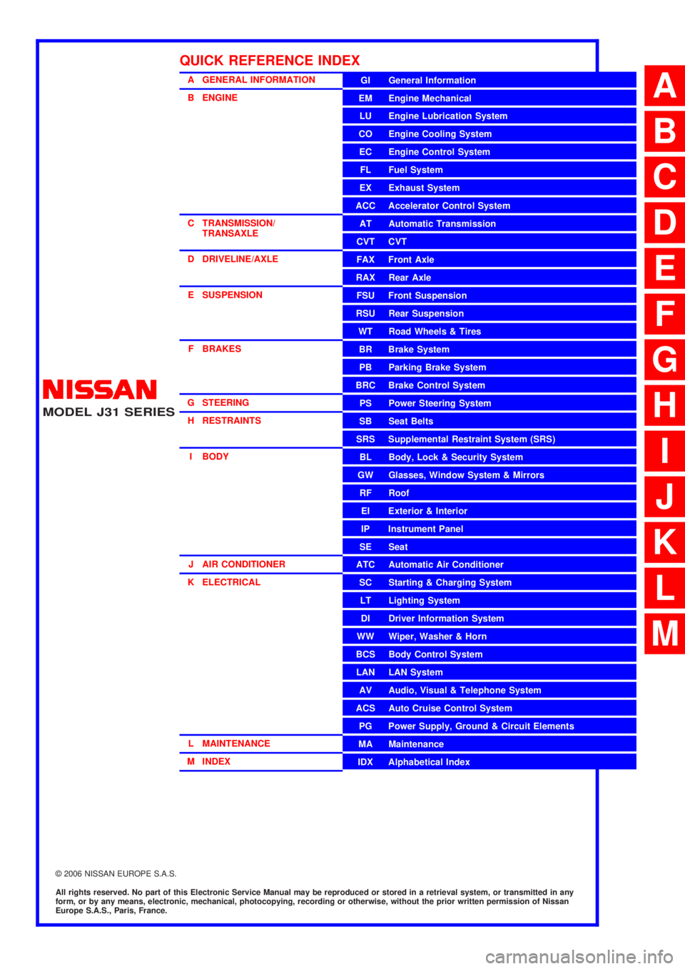
A GENERAL INFORMATION
B ENGINE
C TRANSMISSION/TRANSAXLE
D DRIVELINE/AXLE
E SUSPENSION
F BRAKES
G STEERING H RESTRAINTS
I BODY
J AIR CONDITIONER
K ELECTRICAL
L MAINTENANCE
M INDEXGI General Information
EM Engine Mechanical
LU Engine Lubrication System
CO Engine Cooling System
EC Engine Control System
FL Fuel System
EX Exhaust System
ACC Accelerator Control System
AT Automatic Transmission
CVT CVT
FAX Front Axle
RAX Rear Axle
FSU Front Suspension
RSU Rear Suspension
WT Road Wheels & Tires
BR Brake System
PB Parking Brake System
BRC Brake Control System
PS Power Steering System
SB Seat Belts
SRS Supplemental Restraint System (SRS)
BL Body, Lock & Security System
GW Glasses, Window System & Mirrors
RF Roof
EI Exterior & Interior
IP Instrument Panel
SE Seat
ATC Automatic Air Conditioner
SC Starting & Charging System
LT Lighting System
DI Driver Information System
WW Wiper, Washer & Horn
BCS Body Control System
LAN LAN System
AV Audio, Visual & Telephone System
ACS Auto Cruise Control System
PG Power Supply, Ground & Circuit Elements
MA Maintenance
IDX Alphabetical Index
QUICK REFERENCE INDEX
A
B
C
D
E
F
G
H
I
J
K
L
M
Page 219 of 3502
TRANSMISSION CONTROL MODULE
AT-211
D
E
F
G
H
I
J
K
L
MA
B
AT
TRANSMISSION CONTROL MODULEPFP:31036
Removal and InstallationBCS001PR
COMPONENTS
REMOVAL
1. Disconnect the battery cable from the negative terminal.
2. Remove Instrument passenger lower panel. Refer to IP-10, "
INSTRUMENT PANEL ASSEMBLY" .
3. Disconnect connector (1) and (2).
1. TCM 2. ECM
Refer to GI section make sure icons (symbol marks) in the figure. Refer to GI-10, "
Components" .
SCIA7873E
SCIA7874E
Page 477 of 3502
TROUBLE DIAGNOSIS
ATC-99
C
D
E
F
G
H
I
K
L
MA
B
AT C
In-vehicle Sensor CircuitBJS000GD
COMPONENT DESCRIPTION
In-vehicle Sensor
The in-vehicle sensor is located on instrument driver lower panel. It
converts variations in temperature of compartment air drawn from
the aspirator into a resistance value. It is then input into the unified
meter and A/C amp.
Aspirator
The aspirator is located on driver’s side of heater & cooling unit
assembly. It produces vacuum pressure due to air discharged from
the heater & cooling unit assembly, continuously taking compartment
air in the aspirator.
RJIA3276E
RJIA3277E
RJIA1804E
Page 488 of 3502
ATC-110
IN-VEHICLE SENSOR
IN-VEHICLE SENSORPFP:27720
Removal and InstallationBJS000H8
REMOVAL
1. Remove instrument driver lower panel. Refer to IP-10, "INSTRUMENT PANEL ASSEMBLY" .
2. Remove mounting screw, and then remove in-vehicle sensor.
INSTALLATION
Installation is basically the reverse order of removal.
RJIA3291E
Page 491 of 3502
BLOWER UNIT
ATC-113
C
D
E
F
G
H
I
K
L
MA
B
AT C
BLOWER UNITPFP:27200
Removal and InstallationBJS000HB
REMOVAL
1. Remove instrument passenger lower panel. Refer to IP-10, "INSTRUMENT PANEL ASSEMBLY" .
2. Remove mounting nuts, and then remove ECM with bracket
attached.
3. Disconnect fan control amp. connector and blower fan motor
connector.
4. Remove harness clip from blower unit.
5. Remove blower unit mounting bolts and screw, and then discon-
nect intake door motor connector.
CAUTION:
Move blower unit rightward, and remove locating pin (1
part) and joint. Then remove blower unit downward.
6. Remove blower unit.
INSTALLATION
Installation is basically the reverse order of removal.
CAUTION:
Make sure locating pin (1 part) and joint are securely inserted.
RJIA3292E
RJIA3293E
Page 493 of 3502
BLOWER MOTOR
ATC-115
C
D
E
F
G
H
I
K
L
MA
B
AT C
BLOWER MOTORPFP:27226
Removal and InstallationBJS000HD
REMOVAL
1. Remove instrument passenger lower panel. Refer to IP-10, "INSTRUMENT PANEL ASSEMBLY" .
2. Disconnect blower motor connector.
3. Remove mounting screws, and then remove blower motor and
motor cover.
INSTALLATION
Installation is basically the reverse order of removal.
RJIA3296E
Page 494 of 3502
ATC-116
FAN CONTROL AMPLIFIER
FAN CONTROL AMPLIFIERPFP:27761
Removal and InstallationBJS000HE
REMOVAL
1. Remove instrument passenger lower panel. Refer to IP-10, "INSTRUMENT PANEL ASSEMBLY" .
2. Remove harness clip.
3. Disconnect fan control amp. connector.
4. Remove mounting screws, and then remove fan control amp.
INSTALLATION
Installation is basically the reverse order of removal.
RJIA3297E
Page 496 of 3502
ATC-118
AIR CONDITIONER FILTER
AIR CONDITIONER FILTERPFP:27277
Removal and InstallationBJS000HG
FUNCTION
Air inside passenger compartment is kept clean at either recircula-
tion or fresh mode by installing air conditioner filter into blower unit.
REPLACEMENT TIMING
Replace air conditioner filter.
Refer to MA-9, "
CHASSIS AND BODY MAINTENANCE" .
When replacing filter, affix a caution label inside the glove box.
REPLACEMENT PROCEDURES
1. Remove instrument passenger lower panel. Refer to IP-10, "INSTRUMENT PANEL ASSEMBLY" .
2. Remove filter cover, and then remove air conditioner filter.
3. Take out air conditioner filter from blower unit.
4. Replace with new one and reinstall on blower unit.
5. Reinstall instrument passenger lower panel.
SJIA0573E
SJIA0994E