COMBINATION METERS
DI-5
C
D
E
F
G
H
I
J
L
MA
B
DI
FA I L - S A F E
Solution When Communication Error Between the Unified Meter and A/C Amp. and the Com-
bination Meter
Function Specifications
SpeedometerReturn to zero when discontinuing communication or receiv-
ing irregular data.
Tachometer
Reset to zero by suspending communication.
Fuel gauge
Illumination control Combination meter illumination When suspending communication, change to nighttime mode.
Odo/trip meter Integrate in response to 8-pulse input.
Shift indicator The display turns off by suspending communication.
Warning buzzer The warning buzzer turns off by suspending communication.
Warning lamp/indicator lampLow water temperature indicator lamp
The lamp turns on by suspending communication. VDC OFF indicator (With VDC)
SLIP indicator (With VDC)
Brake warning lamp
ABS warning lamp
ASCD CRUISE indicator lamp
The lamp turns off by suspending communication. ASCD SET indicator lamp
Turn signal indicator lamp
High-beam indicator lamp
Front fog indicator lamp
Rear fog indicator lamp
Oil pressure warning lamp
Door warning lamp
High water temperature warning lamp
Malfunction indicator lamp
A/T CHECK warning lamp
CVT indicator lamp
KEY warning lamp
LOCK warning lamp
SRS-36
DRIVER AIR BAG MODULE
CAUTION:
�Always work from the side of driver air bag module.
�Always place driver air bag module with pad side facing
upward.
�Do not insert any foreign objects (screwdriver, etc.) into
driver air bag module.
�Do not disassemble driver air bag module.
�Do not use old bolts after removal; replace with new bolts.
�Do not expose the driver air bag module to temperatures
exceeding 90°C (194°F).
�Replace driver air bag module if it has been dropped or sus-
tained an impact.
�Do not allow oil, grease or water to come in contact with the
driver air bag module.
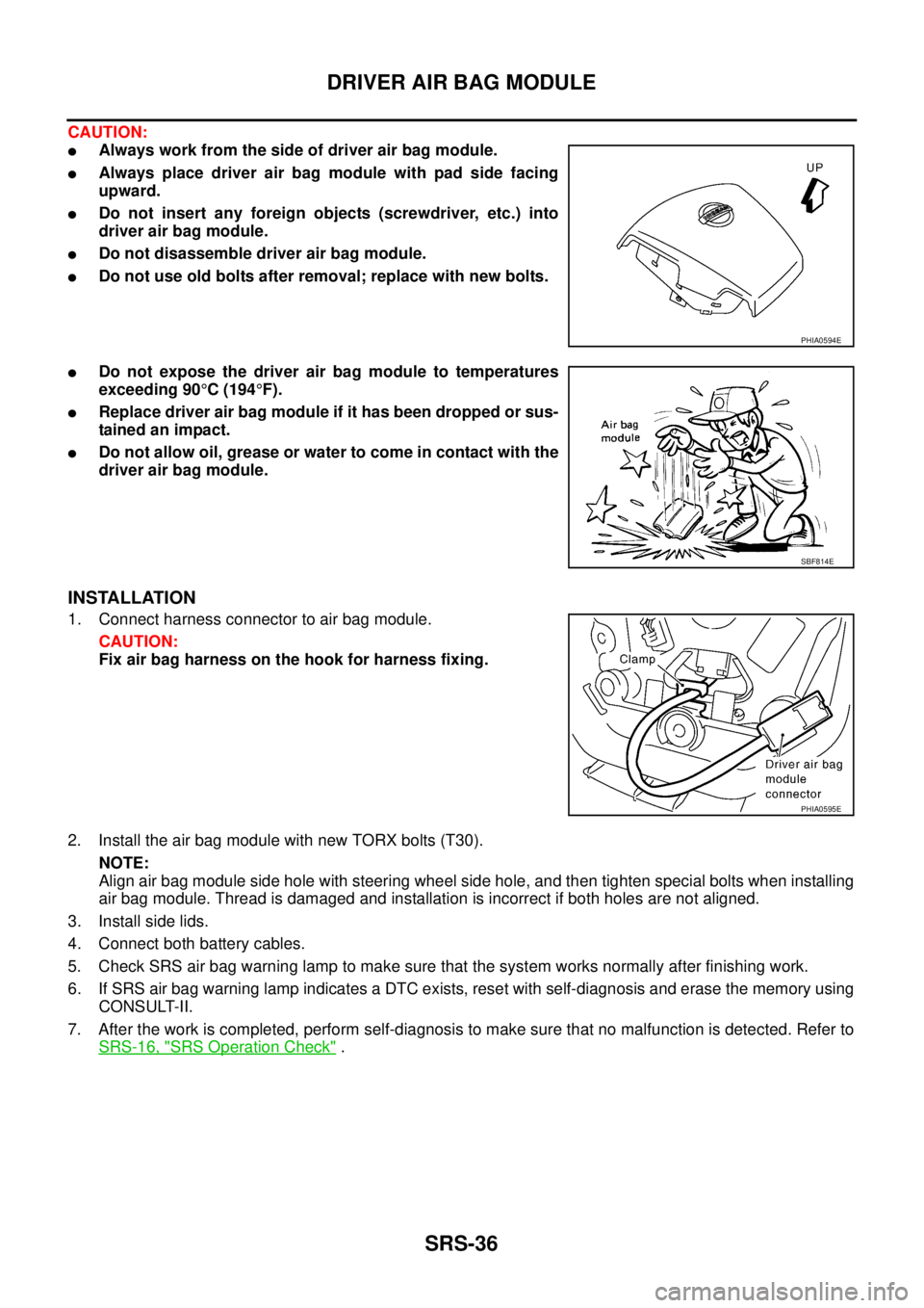
INSTALLATION
1. Connect harness connector to air bag module.
CAUTION:
Fix air bag harness on the hook for harness fixing.
2. Install the air bag module with new TORX bolts (T30).
NOTE:
Align air bag module side hole with steering wheel side hole, and then tighten special bolts when installing
air bag module. Thread is damaged and installation is incorrect if both holes are not aligned.
3. Install side lids.
4. Connect both battery cables.
5. Check SRS air bag warning lamp to make sure that the system works normally after finishing work.
6. If SRS air bag warning lamp indicates a DTC exists, reset with self-diagnosis and erase the memory using
CONSULT-II.
7. After the work is completed, perform self-diagnosis to make sure that no malfunction is detected. Refer to
SRS-16, "
SRS Operation Check" .
PHIA0594E
SBF814E
PHIA0595E