Page 391 of 3502

PRECAUTIONS
ATC-13
C
D
E
F
G
H
I
K
L
MA
B
AT C
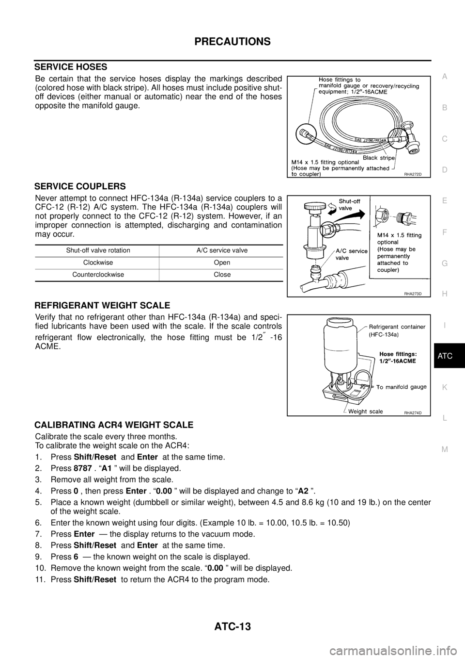
SERVICE HOSES
Be certain that the service hoses display the markings described
(colored hose with black stripe). All hoses must include positive shut-
off devices (either manual or automatic) near the end of the hoses
opposite the manifold gauge.
SERVICE COUPLERS
Never attempt to connect HFC-134a (R-134a) service couplers to a
CFC-12 (R-12) A/C system. The HFC-134a (R-134a) couplers will
not properly connect to the CFC-12 (R-12) system. However, if an
improper connection is attempted, discharging and contamination
may occur.
REFRIGERANT WEIGHT SCALE
Verify that no refrigerant other than HFC-134a (R-134a) and speci-
fied lubricants have been used with the scale. If the scale controls
refrigerant flow electronically, the hose fitting must be 1/2
″ -16
ACME.
CALIBRATING ACR4 WEIGHT SCALE
Calibrate the scale every three months.
To calibrate the weight scale on the ACR4:
1. Press Shift/Reset and Enter at the same time.
2. Press 8787 . “A1 ” will be displayed.
3. Remove all weight from the scale.
4. Press 0 , then press Enter . “0.00 ” will be displayed and change to “A2 ”.
5. Place a known weight (dumbbell or similar weight), between 4.5 and 8.6 kg (10 and 19 lb.) on the center
of the weight scale.
6. Enter the known weight using four digits. (Example 10 lb. = 10.00, 10.5 lb. = 10.50)
7. Press Enter — the display returns to the vacuum mode.
8. Press Shift/Reset and Enter at the same time.
9. Press 6 — the known weight on the scale is displayed.
10. Remove the known weight from the scale. “0.00 ” will be displayed.
11 . P r e s s Shift/Reset to return the ACR4 to the program mode.
RHA272D
Shut-off valve rotation A/C service valve
Clockwise Open
Counterclockwise Close
RHA273D
RHA274D
Page 583 of 3502
INTEGRATED DISPLAY SYSTEM
AV-55
C
D
E
F
G
H
I
J
L
MA
B
AV
On Board Self-Diagnosis FunctionBKS00228
DESCRIPTION
When performing self-diagnosis mode, the following menu is displayed.
DIAGNOSIS ITEM
Self-Diagnosis ModeBKS00229
OPERATION PROCEDURES
1. Start the engine.
2. Turn the audio system OFF.
3. While pressing the “MUTE” button, turn the volume control dial
clockwise or counterclockwise for 30 clicks or more. (When the
self-diagnosis mode is started, a short beep will be heard.)
4. Initial diagnosis screen is displayed.
�Perform diagnosis according to the audio preset No. “1, 2, 3,
4”.
FULL BLINK
All display unit segments turn ON.
Diagnosis itemFunction
switchDescription
FULL BLINK 1 All display unit segments turn ON.
HVAC DIAG 2 Self-diagnosis of air conditioner system is performed.
VERSION 3 Software version of each unit is displayed.
DIAG END 4 Exit from self-diagnosis mode and return to normal screen.
SKIB0828E
SKIA7023J
SKIA7024J
Page 3412 of 3502

SRS-38
SPIRAL CABLE
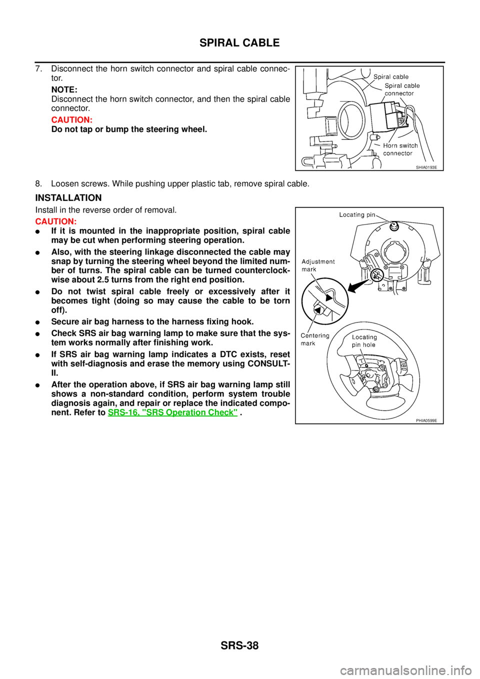
7. Disconnect the horn switch connector and spiral cable connec-
tor.
NOTE:
Disconnect the horn switch connector, and then the spiral cable
connector.
CAUTION:
Do not tap or bump the steering wheel.
8. Loosen screws. While pushing upper plastic tab, remove spiral cable.
INSTALLATION
Install in the reverse order of removal.
CAUTION:
�If it is mounted in the inappropriate position, spiral cable
may be cut when performing steering operation.
�Also, with the steering linkage disconnected the cable may
snap by turning the steering wheel beyond the limited num-
ber of turns. The spiral cable can be turned counterclock-
wise about 2.5 turns from the right end position.
�Do not twist spiral cable freely or excessively after it
becomes tight (doing so may cause the cable to be torn
off).
�Secure air bag harness to the harness fixing hook.
�Check SRS air bag warning lamp to make sure that the sys-
tem works normally after finishing work.
�If SRS air bag warning lamp indicates a DTC exists, reset
with self-diagnosis and erase the memory using CONSULT-
II.
�After the operation above, if SRS air bag warning lamp still
shows a non-standard condition, perform system trouble
diagnosis again, and repair or replace the indicated compo-
nent. Refer to SRS-16, "
SRS Operation Check" .
SHIA0193E
PHIA0599E