Page 2093 of 3502
REAR PARCEL SHELF FINISHER
EI-45
C
D
E
F
G
H
J
K
L
MA
B
EI
REAR WINDOW SUNSHADE
Removal
1. Remove rear parcel shelf finisher. Refer to EI-43, "REAR PARCEL SHELF FINISHER" .
2. Disconnect rear window sunshade harness connector.
3. Remove rear window sunshade mounting bolts.
4. Lift up rear window sunshade and pull out locating pin from body side panel hole, and then remove rear
window sunshade.
Installation
Install in the reverse order of removal.
PIIA9536E
Page 2101 of 3502
FLOOR TRIM
EI-53
C
D
E
F
G
H
J
K
L
MA
B
EI
8. Remove A/C drain hose from A/C unit.
9. Cut floor trim tunnel upper side (Section A, B, C) using cutter
knife.
10. Disengage floor trim securing clips after cutting, and then pull
out floor trim toward vehicle outside.
INSTALLATION
Install in the reverse order of removal.
CAUTION:
Install by cutting Section A, B, C on center of floor tunnel when replacing floor trim with a new one.
After that, ensure matching quality between floor trim and center console lid by tucking.
PIIA6273E
PIIA6268E
PIIA7125E
Page 2105 of 3502

HEADLINING
EI-57
C
D
E
F
G
H
J
K
L
MA
B
EI
14. Push headlining toward rear of vehicle after removing, Pull out
clip holder of headlining rear end from clips and remove roof
hook on front of sunroof opening at the same time.
15. Remove front end of headlining right side from front door LH
opening so as to avoid center console finisher upper surface
after pulling out.
CAUTION:
�When removing, 2 workers are required. (1 for each front
and rear of headlining)
�Cover center console finisher upper surface with a shop
cloth so as to prevent it from being damaged.
�Set A/T selector lever to D position, and make a space to
remove front end of headlining right side.
�Do not bend headlining when removing.
16. Remove the following parts after removing headlining.
�Personal lamp (LH/RH)
�Roof harness assembly
�Spot lamp holder assembly
�Headlining rear end clip (removing on roof rail)
INSTALLATION
Install in the reverse order of removal.
CAUTION:
Install headlining assembly after inserting clips to clip holder of headlining rear end.
PIIA7119E
PIIA7120E
Page 2107 of 3502
TRUNK ROOM TRIM & TRUNK LID FINISHER
EI-59
C
D
E
F
G
H
J
K
L
MA
B
EI
6. Remove trunk rear garnish mounting clips (net hook), and the
remove trunk rear garnish (LH/RH).
7. Remove trunk rear finisher mounting clips, and the remove trunk rear finisher.
8. Remove dual-lock fastener from back of trunk lower finisher, and then remove trunk lower finisher.
9. Disengage trunk upper finisher mounting clips and hooks, and remove trunk upper finisher.
10. Remove trunk wheelhouse finisher mounting clips, and the remove trunk wheelhouse finisher (LH/RH).
INSTALLATION
Install in the reverse order of removal.
REMOVAL AND INSTALLATION FOR TRUNK LID FINISHER INNER
Removal
1. Fully open trunk lid assembly.
2. Remove clips of trunk lid finisher inner.
3. Remove trunk lid finisher.
Installation
Install in the reverse order of removal.
NOTE:
Secure emergency handle to dual-lock fastener of trunk lid trim surface after installing.
PIIA6276E
PIIA6266E
Page 2124 of 3502
EM-16
[QR]
DRIVE BELTS
CAUTION:
Do not loosen the hexagonal part in center of drive belt auto-tensioner pulley (Do not turn it counter-
clockwise). If turned counterclockwise, the complete drive belt auto-tensioner must be replaced as a
unit, including the pulley.
INSTALLATION
Note the following, and install in the reverse order of removal.
�When installing drive belt auto-tensioner, be careful not to interfere with water pump pulley.
CAUTION:
�If there is damage greater than peeled paint, replace drive belt auto-tensioner.
�Do not swap the pulley between new and old drive belt auto-tensioner.
Page 2126 of 3502
EM-18
[QR]
AIR CLEANER AND AIR DUCT
INSPECTION AFTER REMOVAL
Inspect air duct assembly for crack or tear.
�Replace air duct assembly, if necessary.
INSTALLATION
Note the following, and install in the reverse order of removal.
�Align marks. Attach each joint. Screw clamps firmly.
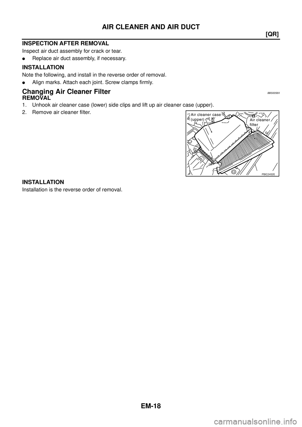
Changing Air Cleaner FilterBBS0058X
REMOVAL
1. Unhook air cleaner case (lower) side clips and lift up air cleaner case (upper).
2. Remove air cleaner filter.
INSTALLATION
Installation is the reverse order of removal.
PBIC2452E
Page 2128 of 3502
![NISSAN TEANA 2003 Service Manual EM-20
[QR]
INTAKE MANIFOLD
2. Remove engine cover.
CAUTION:
Be careful not to damage or scratch engine cover.
3. Remove air cleaner case (upper) with mass air flow sensor and air duct assembly. Refe](/manual-img/5/57392/w960_57392-2127.png "NISSAN TEANA 2003 Service Manual EM-20
[QR]
INTAKE MANIFOLD
2. Remove engine cover.
CAUTION:
Be careful not to damage or scratch engine cover.
3. Remove air cleaner case (upper) with mass air flow sensor and air duct assembly. Refe")
EM-20
[QR]
INTAKE MANIFOLD
2. Remove engine cover.
CAUTION:
Be careful not to damage or scratch engine cover.
3. Remove air cleaner case (upper) with mass air flow sensor and air duct assembly. Refer to EM-17, "
AIR
CLEANER AND AIR DUCT" .
4. Remove quick connector cap, and disconnect quick connector
at engine side. Refer to EM-34, "
FUEL INJECTOR AND FUEL
TUBE" .
5. Remove electric throttle control actuator with the following procedure:
a. Disconnect harness connector.
b. Loosen mounting bolts in reverse order as shown in the figure,
and remove electric throttle control actuator and gasket.
CAUTION:
�Handle carefully to avoid any shock to electric throttle
control actuator.
�Do not disassemble.
6. Disconnect harness, power steering piping, vacuum hose and PCV hose from intake manifold, and move
them aside.
7. Remove intake manifold support and gasket.
8. Disconnect sub-harness from fuel injector. Refer to EM-34, "
FUEL INJECTOR AND FUEL TUBE" .
9. Remove fuel tube and fuel injector assembly from intake manifold. Refer to EM-34, "
FUEL INJECTOR
AND FUEL TUBE" .
PBIC2423E
PBIC2175E
EMJ1612D
Page 2129 of 3502
![NISSAN TEANA 2003 Service Manual INTAKE MANIFOLD
EM-21
[QR]
C
D
E
F
G
H
I
J
K
L
MA
EM
10. Loosen mounting nuts and bolts in reverse order as shown in
the figure, and remove intake manifold (with fuel tube and fuel
injector assembly](/manual-img/5/57392/w960_57392-2128.png "NISSAN TEANA 2003 Service Manual INTAKE MANIFOLD
EM-21
[QR]
C
D
E
F
G
H
I
J
K
L
MA
EM
10. Loosen mounting nuts and bolts in reverse order as shown in
the figure, and remove intake manifold (with fuel tube and fuel
injector assembly")
INTAKE MANIFOLD
EM-21
[QR]
C
D
E
F
G
H
I
J
K
L
MA
EM
10. Loosen mounting nuts and bolts in reverse order as shown in
the figure, and remove intake manifold (with fuel tube and fuel
injector assembly) and gasket.
CAUTION:
�Do not disassemble intake manifold.
�Cover engine openings to avoid entry of foreign materi-
als.
NOTE:
Disregard No. 6 when loosening.
INSTALLATION
Note the following, and install in the reverse order of removal.
Intake Manifold
�If stud bolts were removed, install them and tighten to the specified torque below.
�Check if gasket is not dropped from the installation groove of intake manifold.
�Tighten in numerical order as shown in the figure.
NOTE:
No. 6 means double tightening of bolt No. 1.
Intake Manifold Support
Tighten mounting bolt from “A” to “B” in order as shown in the figure.
NOTE:
Tighten “A” in the figure together with electric throttle control actua-
tor. Refer to EM-21, "
Electric Throttle Control Actuator" for the tight-
ening procedure.
Electric Throttle Control Actuator
�Tighten mounting bolts equally and diagonally in several steps
and in numerical order as shown in the figure.
�Perform the “Throttle Valve Closed Position Learning” when har-
ness connector of electric throttle control actuator is discon-
nected. Refer to EC-47, "
Throttle Valve Closed Position
Learning" .
�Perform the “Idle Air Volume Learning” and “Throttle Valve
Closed Position Learning” when electric throttle control actuator
is replaced. Refer to EC-47, "
Idle Air Volume Learning" .
PBIC2173E
: 10.8 N·m (1.1 kg-m, 8 ft-lb)
PBIC2173E
PBIC2628E
EMJ1612D

 using cutter
knife.
10. Disengage floor trim securing clips a")
, and the
remove trunk rear garnish (LH/RH).
7. Remove trunk rear finisher")
![NISSAN TEANA 2003 Service Manual EM-16
[QR]
DRIVE BELTS
CAUTION:
Do not loosen the hexagonal part in center of drive belt auto-tensioner pulley (Do not turn it counter-
clockwise). If turned counterclockwise, the complete drive bel](/manual-img/5/57392/w960_57392-2123.png "NISSAN TEANA 2003 Service Manual EM-16
[QR]
DRIVE BELTS
CAUTION:
Do not loosen the hexagonal part in center of drive belt auto-tensioner pulley (Do not turn it counter-
clockwise). If turned counterclockwise, the complete drive bel")