Page 2132 of 3502
![NISSAN TEANA 2003 Service Manual EM-24
[QR]
EXHAUST MANIFOLD AND THREE WAY CATALYST
c. Using heated oxygen sensor wrench (SST), remove heated oxy-
gen sensors.
CAUTION:
�Be careful not to damage heated oxygen sensor.
�Discard any h](/manual-img/5/57392/w960_57392-2131.png "NISSAN TEANA 2003 Service Manual EM-24
[QR]
EXHAUST MANIFOLD AND THREE WAY CATALYST
c. Using heated oxygen sensor wrench (SST), remove heated oxy-
gen sensors.
CAUTION:
�Be careful not to damage heated oxygen sensor.
�Discard any h")
EM-24
[QR]
EXHAUST MANIFOLD AND THREE WAY CATALYST
c. Using heated oxygen sensor wrench (SST), remove heated oxy-
gen sensors.
CAUTION:
�Be careful not to damage heated oxygen sensor.
�Discard any heated oxygen sensor which has been
dropped onto a hard surface such as a concrete floor;
replace with a new one.
6. Remove exhaust manifold stay.
7. Remove exhaust manifold cover (upper).
8. Loosen nuts in reverse order as shown in the figure to remove
exhaust manifold and three way catalyst assembly.
NOTE:
Disregard No. 6 and 7 when loosening.
9. Remove gasket.
CAUTION:
Cover engine openings to avoid entry of foreign materials.
10. Remove exhaust manifold cover (lower) and three way catalyst cover from exhaust manifold and three
way catalyst assembly.
INSPECTION AFTER REMOVAL
Surface Distortion
�Using straightedge and feeler gauge, check the surface distor-
tion of exhaust manifold and three way catalyst assembly mating
surface.
�If it exceeds the limit, replace exhaust manifold and three way
catalyst assembly.
INSTALLATION
Note the following, and install in the reverse order of removal.
Exhaust Manifold
�If stud bolts were removed, install them and tighten to the specified torque below.
KBIA0094E
KBIA0045E
Limit : 0.3 mm (0.012 in)
KBIA0046E
: 14.7 N·m (1.5 kg-m, 11 ft-lb)
Page 2135 of 3502
![NISSAN TEANA 2003 Service Manual OIL PAN AND OIL STRAINER
EM-27
[QR]
C
D
E
F
G
H
I
J
K
L
MA
EM
a. Loosen mounting bolts in reverse order as shown in the figure.
b. Insert seal cutter (SST) between oil pan (upper) and oil pan
(lower](/manual-img/5/57392/w960_57392-2134.png "NISSAN TEANA 2003 Service Manual OIL PAN AND OIL STRAINER
EM-27
[QR]
C
D
E
F
G
H
I
J
K
L
MA
EM
a. Loosen mounting bolts in reverse order as shown in the figure.
b. Insert seal cutter (SST) between oil pan (upper) and oil pan
(lower")
OIL PAN AND OIL STRAINER
EM-27
[QR]
C
D
E
F
G
H
I
J
K
L
MA
EM
a. Loosen mounting bolts in reverse order as shown in the figure.
b. Insert seal cutter (SST) between oil pan (upper) and oil pan
(lower).
CAUTION:
�Be careful not to damage the mating surfaces.
�Do not insert screwdriver, this will damage the mating
surfaces.
c. Slide seal cutter by tapping on the side of the tool with hammer.
9. Remove oil strainer.
10. Remove oil pan (upper) with the following procedure:
a. Remove rear plate cover, and four transaxle joint bolts. Refer to AT- 2 4 1 , "
TRANSAXLE ASSEMBLY" .
b. Securely support bottom of transaxle with suitable transmission jack.
c. Remove engine mounting related parts below. Refer to EM-77, "
ENGINE ASSEMBLY" .
�RH engine mounting insulator bolts (vehicle side)
�Front engine mounting through-bolt
�Rear engine mounting through-bolt
d. Loosen bolts in reverse order as shown in the figure.
NOTE:
Disregard No.12 and 17 when loosening.
e. Insert seal cutter (SST) between oil pan (upper) and cylinder
block, and slide it by tapping on the side of the tool with hammer.
CAUTION:
�Be careful not to damage the mating surfaces.
�Do not insert screwdriver, this will damage the mating
surfaces.
f. Lift up engine and transaxle assembly with transmission jack to make a room for pulling oil pan (upper)
out.
KBIA0096E
SEM365EA
SBIA0233E
SEM365EA
Page 2137 of 3502
OIL PAN AND OIL STRAINER
EM-29
[QR]
C
D
E
F
G
H
I
J
K
L
MA
EM
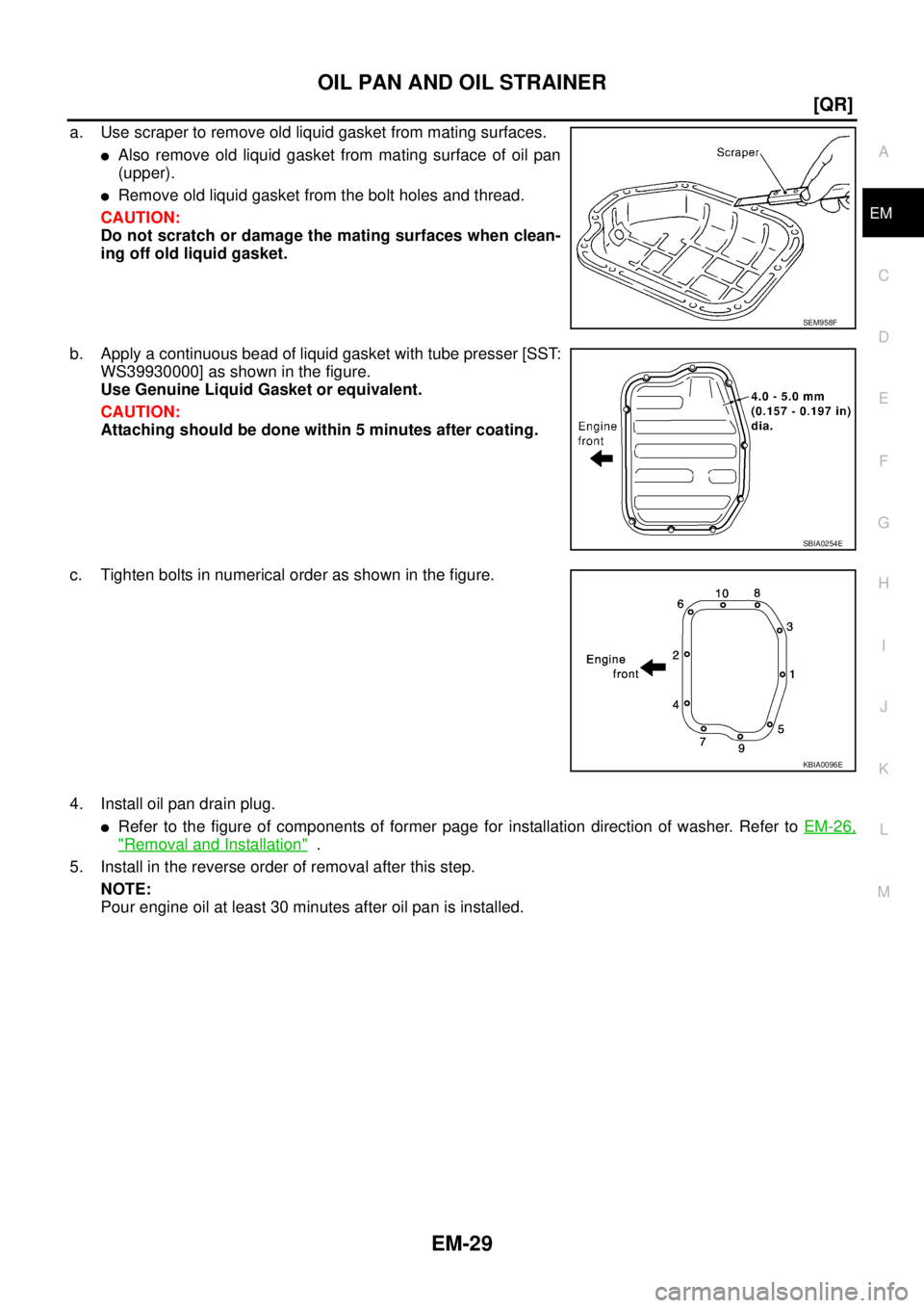
a. Use scraper to remove old liquid gasket from mating surfaces.
�Also remove old liquid gasket from mating surface of oil pan
(upper).
�Remove old liquid gasket from the bolt holes and thread.
CAUTION:
Do not scratch or damage the mating surfaces when clean-
ing off old liquid gasket.
b. Apply a continuous bead of liquid gasket with tube presser [SST:
WS39930000] as shown in the figure.
Use Genuine Liquid Gasket or equivalent.
CAUTION:
Attaching should be done within 5 minutes after coating.
c. Tighten bolts in numerical order as shown in the figure.
4. Install oil pan drain plug.
�Refer to the figure of components of former page for installation direction of washer. Refer to EM-26,
"Removal and Installation" .
5. Install in the reverse order of removal after this step.
NOTE:
Pour engine oil at least 30 minutes after oil pan is installed.
SEM958F
SBIA0254E
KBIA0096E
Page 2139 of 3502
IGNITION COIL
EM-31
[QR]
C
D
E
F
G
H
I
J
K
L
MA
EM
IGNITION COILPFP:22448
Removal and InstallationBBS00591
REMOVAL
1. Remove engine cover. Refer to EM-19, "INTAKE MANIFOLD" .
2. Disconnect harness connector from ignition coil.
3. Remove ignition coil.
CAUTION:
Do not drop or shock it.
INSTALLATION
Installation is the reverse order of removal.
1. Ignition coil 2. Spark plug 3. Rocker cover
KBIA1974J
Page 2141 of 3502
SPARK PLUG(PLATINUM-TIPPED TYPE)
EM-33
[QR]
C
D
E
F
G
H
I
J
K
L
MA
EM
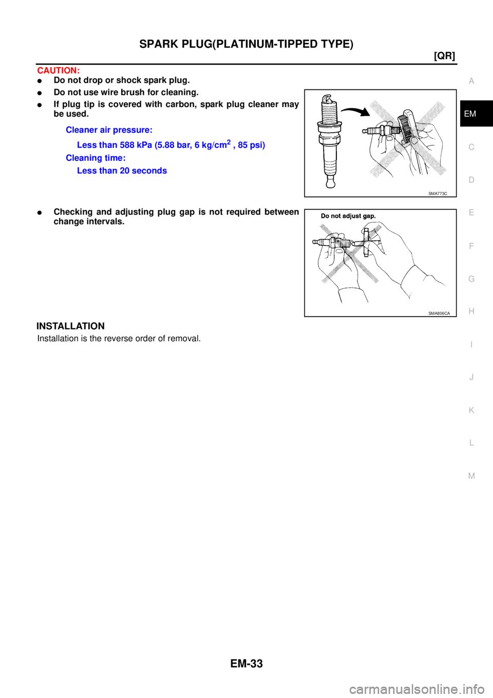
CAUTION:
�Do not drop or shock spark plug.
�Do not use wire brush for cleaning.
�If plug tip is covered with carbon, spark plug cleaner may
be used.
�Checking and adjusting plug gap is not required between
change intervals.
INSTALLATION
Installation is the reverse order of removal.Cleaner air pressure:
Less than 588 kPa (5.88 bar, 6 kg/cm
2 , 85 psi)
Cleaning time:
Less than 20 seconds
SMA773C
SMA806CA
Page 2144 of 3502
![NISSAN TEANA 2003 Service Manual EM-36
[QR]
FUEL INJECTOR AND FUEL TUBE
8. Loosen mounting bolts in reverse order as shown in the figure.
9. Remove fuel tube protector.
10. Pull out fuel tube and fuel injector assembly rearward of](/manual-img/5/57392/w960_57392-2143.png "NISSAN TEANA 2003 Service Manual EM-36
[QR]
FUEL INJECTOR AND FUEL TUBE
8. Loosen mounting bolts in reverse order as shown in the figure.
9. Remove fuel tube protector.
10. Pull out fuel tube and fuel injector assembly rearward of")
EM-36
[QR]
FUEL INJECTOR AND FUEL TUBE
8. Loosen mounting bolts in reverse order as shown in the figure.
9. Remove fuel tube protector.
10. Pull out fuel tube and fuel injector assembly rearward of engine.
CAUTION:
�When removing, be careful to avoid any interference with fuel injector.
�Use a shop cloth to absorb any fuel leaks from fuel tube.
11. Remove fuel injector from fuel tube with the following procedure:
a. Open and remove clip.
b. Remove fuel injector from fuel tube by pulling straight.
CAUTION:
�Be careful with remaining fuel that may go out from fuel
tube.
�Be careful not to damage fuel injector nozzle during
removal.
�Do not bump or drop fuel injector.
�Do not disassemble fuel injector.
INSTALLATION
1. Note the following, and install O-rings to fuel injector.
CAUTION:
�Upper and lower O-rings are different. Be careful not to confuse them.
�Handle O-ring with bare hands. Do not wear gloves.
�Lubricate O-ring with new engine oil.
�Do not clean O-ring with solvent.
�Make sure that O-ring and its mating part are free of foreign material.
�When installing O-ring, be careful not to scratch it with tool or fingernails. Also be careful not to
twist or stretch O-ring. If O-ring was stretched while it was being attached, do not insert it
quickly into fuel tube.
�Insert O-ring straight into fuel tube. Do not decenter or twist it.
PBIC2180E
SBIA0364E
Fuel tube side : Black
Nozzle side : Green
Page 2146 of 3502
![NISSAN TEANA 2003 Service Manual EM-38
[QR]
FUEL INJECTOR AND FUEL TUBE
�Insert until you hear a “click” sound and actually feel the engagement.
�To avoid misidentification of engagement with a similar sound, be sure to perform](/manual-img/5/57392/w960_57392-2145.png "NISSAN TEANA 2003 Service Manual EM-38
[QR]
FUEL INJECTOR AND FUEL TUBE
�Insert until you hear a “click” sound and actually feel the engagement.
�To avoid misidentification of engagement with a similar sound, be sure to perform")
EM-38
[QR]
FUEL INJECTOR AND FUEL TUBE
�Insert until you hear a “click” sound and actually feel the engagement.
�To avoid misidentification of engagement with a similar sound, be sure to perform the next
step.
c. Before clamping fuel feed hose with hose clamps, pull quick connector hard by hand holding “A” position.
Make sure it is completely engaged (connected) so that it does not come out from fuel tube.
d. Install quick connector cap to quick connector connection. (On
both the engine side and the vehicle side)
�Install so that the arrow mark on the side faces up.
CAUTION:
�Make sure that quick connector and fuel tube are
securely fit into quick connector cap installation groove.
�If quick connector cap cannot be installed smoothly,
quick connector may have not been installed correctly.
Check connection again.
NOTE:
There is quick connector cap for the engine side and for the
vehicle side, and they have different shapes. The figure shows engine side as an example.
8. Install fuel feed hose to hose clamp.
9. Install in the reverse order of removal after this step.
INSPECTION AFTER INSTALLATION
Check on Fuel Leaks
1. Apply fuel pressure to fuel lines with turning ignition switch “ON” (with engine stopped). Then make sure
there are no fuel leaks at connections.
NOTE:
Use mirrors for checking on invisible points.
2. Start engine. With engine speed increased, make sure again there are no fuel leaks at connections.
CAUTION:
Do not touch the engine immediately after stopped as engine becomes extremely hot.
PBIC2348E
Page 2147 of 3502
ROCKER COVER
EM-39
[QR]
C
D
E
F
G
H
I
J
K
L
MA
EM
ROCKER COVERPFP:13264
Removal and InstallationBBS00594
REMOVAL
1. Remove engine cover. Refer to EM-19, "INTAKE MANIFOLD" .
2. Disconnect PCV hoses from rocker cover.
3. Remove ignition coil. Refer to EM-31, "
IGNITION COIL" .
4. Remove PCV valve and O-ring from rocker cover, if necessary.
5. Remove oil filler cap from rocker cover, if necessary.
6. Loosen bolts in reverse order shown in the figure.
7. Remove rocker cover gasket from rocker cover.
8. Use scraper to remove all traces of liquid gasket from cylinder head and camshaft bracket (No. 1).
CAUTION:
Do not scratch or damage the mating surface when cleaning off old liquid gasket.
1. PCV hose 2. O-ring 3. PCV valve
4. PCV hose 5. Oil filler cap 6. Rocker cover
7. Rocker cover gasket
PBIC2623E
KBIA0242E
![NISSAN TEANA 2003 Service Manual IGNITION COIL
EM-31
[QR]
C
D
E
F
G
H
I
J
K
L
MA
EM
IGNITION COILPFP:22448
Removal and InstallationBBS00591
REMOVAL
1. Remove engine cover. Refer to EM-19, "INTAKE MANIFOLD" .
2. Disconnect harness](/manual-img/5/57392/w960_57392-2138.png "NISSAN TEANA 2003 Service Manual IGNITION COIL
EM-31
[QR]
C
D
E
F
G
H
I
J
K
L
MA
EM
IGNITION COILPFP:22448
Removal and InstallationBBS00591
REMOVAL
1. Remove engine cover. Refer to EM-19, \"INTAKE MANIFOLD\" .
2. Disconnect harness")
![NISSAN TEANA 2003 Service Manual ROCKER COVER
EM-39
[QR]
C
D
E
F
G
H
I
J
K
L
MA
EM
ROCKER COVERPFP:13264
Removal and InstallationBBS00594
REMOVAL
1. Remove engine cover. Refer to EM-19, "INTAKE MANIFOLD" .
2. Disconnect PCV hoses](/manual-img/5/57392/w960_57392-2146.png "NISSAN TEANA 2003 Service Manual ROCKER COVER
EM-39
[QR]
C
D
E
F
G
H
I
J
K
L
MA
EM
ROCKER COVERPFP:13264
Removal and InstallationBBS00594
REMOVAL
1. Remove engine cover. Refer to EM-19, \"INTAKE MANIFOLD\" .
2. Disconnect PCV hoses")