Page 690 of 3502
![NISSAN TEANA 2003 Service Manual BL-32
POWER DOOR LOCK SYSTEM
BCM Power Supply and Ground CircuitBIS000W5
1. CHECK FUSE
�Check 15A fuse [No.17, located in fuse block (J/B)]
�Check 15A fuse [No.18, located in fuse block (J/B)] (With](/manual-img/5/57392/w960_57392-689.png "NISSAN TEANA 2003 Service Manual BL-32
POWER DOOR LOCK SYSTEM
BCM Power Supply and Ground CircuitBIS000W5
1. CHECK FUSE
�Check 15A fuse [No.17, located in fuse block (J/B)]
�Check 15A fuse [No.18, located in fuse block (J/B)] (With")
BL-32
POWER DOOR LOCK SYSTEM
BCM Power Supply and Ground CircuitBIS000W5
1. CHECK FUSE
�Check 15A fuse [No.17, located in fuse block (J/B)]
�Check 15A fuse [No.18, located in fuse block (J/B)] (With Intelligent Key)
�Check 50A fusible link (letter M located in the fuse and fusible link box)
NOTE:
Refer to BL-21, "
Component Parts and Harness Connector Location" .
OK or NG
OK >> GO TO 2.
NG >> If fuse is blown, be sure to eliminate cause of malfunction before installing new fuse, refer to PG-
3, "POWER SUPPLY ROUTING CIRCUIT" .
2. CHECK POWER SUPPLY CIRCUIT
1. Turn ignition switch OFF.
2. Disconnect BCM connector.
3. Check voltage between BCM connector M4 terminals 42, 55 and
ground.
OK or NG
OK >> GO TO 3.
NG >> Repair or replace BCM power supply circuit.
3. CHECK GROUND CIRCUIT
Check continuity between BCM connector M4 terminal 52 and
ground.
OK or NG
OK >> Power supply and ground circuit are OK.
NG >> Repair or replace BCM ground circuit.42 (Y/R) – Ground : Battery voltage
55 (W/B) – Ground : Battery voltage
PIIA6374E
52 (B) – Ground : Continuity should exist.
PIIA9131E
Page 704 of 3502

BL-46
REMOTE KEYLESS ENTRY SYSTEM
REMOTE KEYLESS ENTRY SYSTEMPFP:28596
Component Parts and Harness Connector LocationBIS000WE
System DescriptionBIS000WF
INPUTS
Power is supplied at all times
�through 50A fusible link (letter M , located in the fuse and fusible link box)
�to BCM terminal 55.
�through 15A fuse [No. 17, located in the fuse block (J/B)]
�to BCM terminal 42.
When the key switch is ON (key is inserted in ignition key cylinder), power is supplied
�through 15A fuse [No. 17, located in the fuse block (J/B)]
�through key switch terminals 1 and 4
�to BCM terminal 37.
When the ignition switch is ACC or ON, power is supplied
�through 10A fuse [No. 6, located in the fuse block (J/B)]
�to BCM terminal 11.
When the ignition switch is ON or START, power is supplied
�through 10A fuse [No. 1, located in the fuse block (J/B)]
1. BCM M3,M4,M5 2. Front door switch B10
(Driver side)3. Rear door switch (LH) B14
4. Key switch and key lock solenoid
connector M345. Trunk lid lock assembly T7
(Trunk room lamp switch)
PIIB8749E
Page 794 of 3502

BL-136
TRUNK LID OPENER
TRUNK LID OPENERPFP:84640
Component Parts and Harness Connector LocationBIS000Y6
System DescriptionBIS000Y7
Power is supplied at all times
�through 50A fusible link (letter M, located in fuse and fusible link box)
�to BCM terminal 55,
�through 15A fuse [No.17, located in fuse block (J/B)]
�to BCM terminal 42.
Ground is supplied
�to BCM terminals 52
�through body grounds M71 and M72.
When trunk lid opener switch is ON (pushed), ground is supplied
�to BCM terminal 30
�through trunk lid opener switch terminals 3 and 2, and
�through body grounds M71 and M72.
And power is supplied
�through BCM terminal 68
�to trunk lid opener actuator terminal 2.
Ground is supplied
�to trunk lid opener actuator terminal 1, and
�through body grounds B214 and B217.
Then BCM unlocks trunk lid opener actuator.
TRUNK LID OPENER OPERATION
When trunk lid opener switch or trunk button of key fob is ON, trunk opener actuator unlocked by BCM.
BCM can unlock trunk lid opener actuator when
�vehicle speed is less than 5 km/h (3MPH)
BCM does not unlock trunk lid opener actuator when
�vehicle speed is more than 5 km/h (3MPH)
1. BCM M3,M4,M5 2. Trunk lid opener switch D9 3. Trunk lid lock assembly T7
(Trunk room lamp switch)
PIIB8753E
Page 2463 of 3502

HOW TO USE THIS MANUAL
GI-17
C
D
E
F
G
H
I
J
K
L
MB
GI
Optional Splice
DESCRIPTION
SGI942
Num-
berItem Description
1 Power condition
�This shows the condition when the system receives battery positive voltage (can be oper-
ated).
2 Fusible link
�The double line shows that this is a fusible link.
�The open circle shows current flow in, and the shaded circle shows current flow out.
3Fusible link/fuse loca-
tion
�This shows the location of the fusible link or fuse in the fusible link or fuse box. For arrange-
ment, refer to PG section, POWER SUPPLY ROUTING.
4Fuse
�The single line shows that this is a fuse.
�The open circle shows current flow in, and the shaded circle shows current flow out.
5 Current rating
�This shows the current rating of the fusible link or fuse.
6 Connectors
�This shows that connector E3 is female and connector M1 is male.
�The G/R wire is located in the 1A terminal of both connectors.
�Terminal number with an alphabet (1A, 5B, etc.) indicates that the connector is SMJ connec-
tor. Refer to PG section, SMJ (SUPER MULTIPLE JUNCTION).
7 Optional splice
�The open circle shows that the splice is optional depending on vehicle application.
8Splice
�The shaded circle shows that the splice is always on the vehicle.
9 Page crossing
�This arrow shows that the circuit continues to an adjacent page.
�The A will match with the A on the preceding or next page.
10 Common connector
�The dotted lines between terminals show that these terminals are part of the same connector.
11 Option abbreviation
�This shows that the circuit is optional depending on vehicle application.
12 Relay
�This shows an internal representation of the relay. For details, refer to PG section, STAN-
DARDIZED RELAY.
13 Connectors
�This shows that the connector is connected to the body or a terminal with bolt or nut.
Page 2511 of 3502
POWER WINDOW SYSTEM
GW-17
C
D
E
F
G
H
J
K
L
MA
B
GW
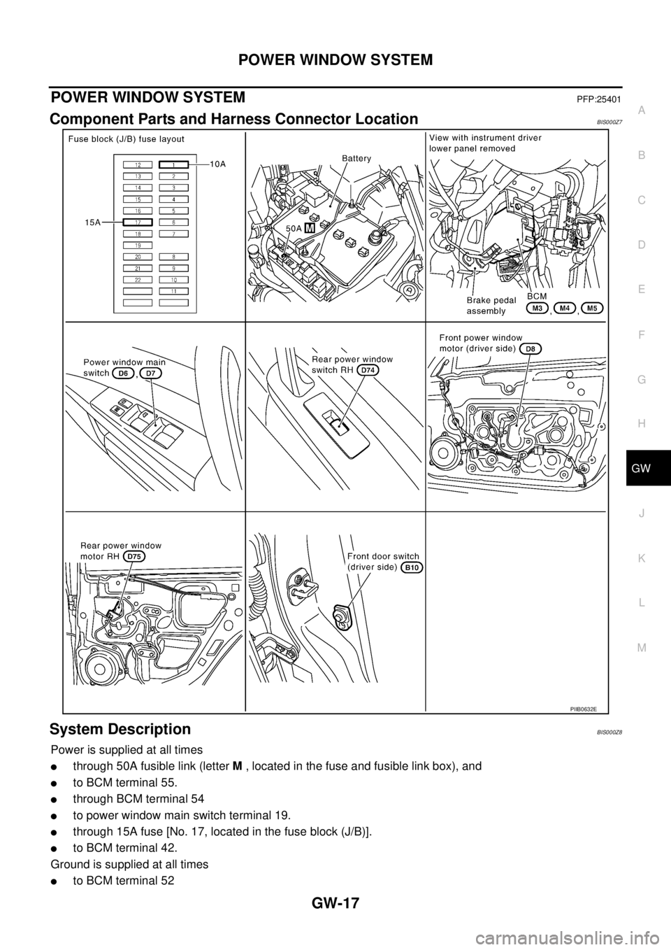
POWER WINDOW SYSTEMPFP:25401
Component Parts and Harness Connector LocationBIS000Z7
System DescriptionBIS000Z8
Power is supplied at all times
�through 50A fusible link (letter M , located in the fuse and fusible link box), and
�to BCM terminal 55.
�through BCM terminal 54
�to power window main switch terminal 19.
�through 15A fuse [No. 17, located in the fuse block (J/B)].
�to BCM terminal 42.
Ground is supplied at all times
�to BCM terminal 52
PIIB0632E
Page 2524 of 3502
![NISSAN TEANA 2003 Service Manual GW-30
POWER WINDOW SYSTEM
Check BCM Power Supply and Ground Circuit BIS000ZF
1. CHECK FUSE
�10A fuse [No.1, located in fuse block (J/B)]
�15A fuse [No.17, located in fuse block (J/B)]
�50A fusible l](/manual-img/5/57392/w960_57392-2523.png "NISSAN TEANA 2003 Service Manual GW-30
POWER WINDOW SYSTEM
Check BCM Power Supply and Ground Circuit BIS000ZF
1. CHECK FUSE
�10A fuse [No.1, located in fuse block (J/B)]
�15A fuse [No.17, located in fuse block (J/B)]
�50A fusible l")
GW-30
POWER WINDOW SYSTEM
Check BCM Power Supply and Ground Circuit BIS000ZF
1. CHECK FUSE
�10A fuse [No.1, located in fuse block (J/B)]
�15A fuse [No.17, located in fuse block (J/B)]
�50A fusible link (letter M , located in the fuse and fusible link box)
NOTE:
Refer to GW-17, "
Component Parts and Harness Connector Location" .
OK or NG
OK >> GO TO 2.
NG >> If fuse is blown out, be sure to eliminate cause of malfunction before installing new fuse.
Refer toPG-3, "
POWER SUPPLY ROUTING CIRCUIT" .
2. CHECK POWER SUPPLY CIRCUIT
Check voltage between BCM connector and ground.
OK or NG
OK >> GO TO 3.
NG >> Check BCM power supply circuit for open or short.
3. CHECK GROUND CIRCUIT
1. Turn ignition switch OFF.
2. Disconnect BCM connector.
3. Check continuity between BCM connector M4 terminal 52 and
ground.
OK or NG
OK >> BCM power supply and ground circuit are OK.
NG >> Check BCM ground circuit for open.
Check Power Window Main Switch Power Supply and Ground Circuit BIS000ZG
1. CHECK POWER SUPPLY CIRCUIT
Check voltage between power window main switch connector and
ground.
OK or NG
OK >> GO TO 2.
NG >> GO TO 3.
ConnectorTerminal (Wire color)
Condition of ignition
switchVoltage [V]
(Approx.)
(+) (-)
M338 (R)
GroundON
Battery voltage 42 (LG)
OFF
M4 55 (W/B)
PIIB1097E
52 (B) – Ground : Continuity should exist.
PIIB1099E
ConnectorTerminal (Wire color)
Condition of ignition
switchVoltage [V]
(Approx.)
(+) (-)
D6 10 (L/W)
GroundON
Battery voltage
D7 19 (R/Y) OFF
PIIB1144E
Page 2548 of 3502
GW-54
REAR WINDOW DEFOGGER
REAR WINDOW DEFOGGERPFP:25350
Component Parts and Harness Connector LocationBIS000ZU
System DescriptionBIS000ZV
The rear window defogger is controlled by BCM and IPDM E/R.
The rear window defogger operates only for approximately 15 minutes.
Power is supplied at all times
�through 20A fuse (No. 75, located in the IPDM E/R)
�to rear window defogger relay terminal 3.
�through 10A fuse (No. 32, located in the fuse and fusible link box)
�to rear window defogger relay terminal 6.
�through 50A fusible link (letter M , located in the fuse and fusible link box)
�to BCM terminal 55.
PIIB2185E
Page 2558 of 3502

GW-64
REAR WINDOW DEFOGGER
Check BCM Power Supply and Ground Circuit BIS00107
First perform the “SELF-DIAG RESULTS” in “BCM” with CONSULT-II, when perform the each trouble
diagnosis. Refer to BCS-14, "
CAN Communication Inspection Using CONSULT-II (Self-Diagnosis)" .
1. CHECK FUSE
�10A fuse [No.1, located in fuse block (J/B)]
�15A fuse [No.17, located in fuse block (J/B)]
�50A fusible link (letter M, located in the fuse and fusible link box).
NOTE:
Refer to GW-54, "
Component Parts and Harness Connector Location" .
OK or NG
OK >> GO TO 2.
NG >> If fuse is blown out, be sure to eliminate cause of malfunction before installing new fuse. Refer to
PG-3, "
POWER SUPPLY ROUTING CIRCUIT" .
2. CHECK POWER SUPPLY CIRCUIT
Check voltage between BCM connector and ground.
OK or NG
OK >> GO TO 3.
NG >> Check BCM power supply circuit for open or short.
3. CHECK GROUND CIRCUIT
1. Turn ignition switch OFF.
2. Disconnect BCM connector.
3. Check continuity between BCM connector M4 terminal 52 and
ground.
OK or NG
OK >> Power supply and ground circuit are OK.
NG >> Check BCM ground circuit for open.
ConnectorTerminal
Condition of ignition
switchVoltage [V]
(Approx.)
(+) (-)
M338 (R)
GroundON
Battery voltage 42 (LG)
OFF
M4 55 (W/B)
PIIB1097E
52 (B) – Ground : Continuity should exist.
PIIB1099E