Page 2193 of 3502
CYLINDER BLOCK
EM-85
[QR]
C
D
E
F
G
H
I
J
K
L
MA
EM
a. Using snap ring pliers, remove snap ring.
b. Heat piston to 60 to 70°C (140 to 158°F) with industrial use drier
or equivalent.
c. Push out piston pin with stick of outer diameter approximately 19
mm (0.75 in).
14. Remove lower cylinder block mounting bolts.
�Before loosening lower cylinder block mounting bolts, measure crankshaft end play. Refer to EM-99,
"CRANKSHAFT END PLAY" .
�Loosen them in reverse order as shown in the figure, and
remove them.
NOTE:
Use TORX socket (size E14) for bolts No. 1 to 10.
15. Remove lower cylinder block.
�U s e s e a l c u t t e r [ S S T: K V 1 0 1111 0 0 ] o r e q u i v a l e n t t o o l t o c u t l i q u i d g a s k e t f o r r e m o v a l .
CAUTION:
Be careful not to damage the mating surfaces.
16. Remove crankshaft.
PBIC1638E
PBIC1639E
PBIC0262E
KBIA0063E
Page 2199 of 3502
![NISSAN TEANA 2003 Service Manual CYLINDER BLOCK
EM-91
[QR]
C
D
E
F
G
H
I
J
K
L
MA
EM
�Install drive plate, reinforcement plate and pilot converter as
shown in the figure.
�Using drift of 33 mm (1.30 in) in diameter, press-fit pilot](/manual-img/5/57392/w960_57392-2198.png "NISSAN TEANA 2003 Service Manual CYLINDER BLOCK
EM-91
[QR]
C
D
E
F
G
H
I
J
K
L
MA
EM
�Install drive plate, reinforcement plate and pilot converter as
shown in the figure.
�Using drift of 33 mm (1.30 in) in diameter, press-fit pilot")
CYLINDER BLOCK
EM-91
[QR]
C
D
E
F
G
H
I
J
K
L
MA
EM
�Install drive plate, reinforcement plate and pilot converter as
shown in the figure.
�Using drift of 33 mm (1.30 in) in diameter, press-fit pilot con-
verter into the end of crankshaft until it stops.
16. Install knock sensor.
�Install knock sensor with connector facing lower left by 45
degrees as shown in the figure.
CAUTION:
�Do not tighten mounting bolt while holding the connec-
tor.
�If any impact by dropping is applied to knock sensor,
replace it with a new one.
NOTE:
�Make sure that there is no foreign material on the cylinder
block mating surface and the back surface of knock sensor.
�Make sure that knock sensor does not interfere with other
parts.
17. Install crankshaft position sensor (POS).
18. Assemble in the reverse order of disassembly after this step.
How to Select Piston and Bearing BBS0059H
DESCRIPTION
*For the service parts, the grade for fitting cannot be selected between piston pin and connecting rod. (Only grade “0” is available.) The
information at the shipment from the plant is described as a reference.
�The identification grade stamped on each part is the grade for the dimension measured in new condition.
This grade cannot apply to reused parts.
�For reused or repaired parts, measure the dimension accurately. Determine the grade by comparing the
measurement with the values of each selection table.
�For details of the measurement method of each part, the reuse standards and the selection method of the
selective fitting parts, refer to the text.
KBIA0075E
KBIA0069E
Selection points Selection parts Selection items Selection methods
Between cylinder block and
crankshaftMain bearingMain bearing grade (bearing
thickness)Determined by match of cylin-
der block bearing housing
grade (inner diameter of hous-
ing) and crankshaft journal
grade (outer diameter of jour-
nal)
Between crankshaft and con-
necting rodConnecting rod bearingConnecting rod bearing grade
(bearing thickness)Combining service grades for
connecting rod big end diame-
ter and crankshaft pin outer
diameter determine connecting
rod bearing selection.
Between cylinder block and pis-
tonPiston and piston pin assembly
(Piston is available together
with piston pin as an assembly.)Piston grade (piston skirt diam-
eter)Piston grade = cylinder bore
grade (inner diameter of bore)
Between piston and connecting
rod
*———
Page 2237 of 3502
![NISSAN TEANA 2003 Service Manual DRIVE BELTS
EM-129
[VQ]
C
D
E
F
G
H
I
J
K
L
MA
EM
�Release the tension by loosing lock nut and turning adjusting nut when adjusting the belt. Tighten
once the lock nut at 4.9 N·m (0.50 Kg-m, 43 in-](/manual-img/5/57392/w960_57392-2236.png "NISSAN TEANA 2003 Service Manual DRIVE BELTS
EM-129
[VQ]
C
D
E
F
G
H
I
J
K
L
MA
EM
�Release the tension by loosing lock nut and turning adjusting nut when adjusting the belt. Tighten
once the lock nut at 4.9 N·m (0.50 Kg-m, 43 in-")
DRIVE BELTS
EM-129
[VQ]
C
D
E
F
G
H
I
J
K
L
MA
EM
�Release the tension by loosing lock nut and turning adjusting nut when adjusting the belt. Tighten
once the lock nut at 4.9 N·m (0.50 Kg-m, 43 in-lb). Then, adjust the belt tension by loosing lock nut
between 45° and 90°.
�Keep engine oil, working fluid and engine coolant away from belt.
�Do not twist or bend belt excessively.
ALTERNATOR AND A/C COMPRESSOR BELT
1. Remove splash guard (RH).
2. Loosen idler pulley lock nut (A).
3. Release the belt tension on idler pulley by turning adjusting nut
(B).
4. Tighten lock nut (A).
5. Loosen lock nut (A) between 45° and 90°.
6. Adjust tension by turning adjusting nut (B).
�For specified belt tension, refer to EM-128, "Checking Drive
Belts" .
7. Tighten lock nut (A).
8. Tighten adjusting nut (B).
POWER STEERING OIL PUMP BELT
1. Remove splash guard (RH).
2. Loosen lock bolt (C).
3. Loosen power steering oil pump mounting bolt (D).
�Bolt head (D) is engine rear side.
4. Adjust tension by turning adjusting bolt (E).
�For specified belt tension, refer to EM-128, "Checking Drive Belts" .
NOTE:
Adjusting bolt (E) is loosened with counterclockwise rotation.
5. Tighten lock bolt (C).
6. Tighten power steering oil pump mounting bolt (D).
Removal and InstallationBBS004VO
REMOVAL
1. Remove splash guard (RH).
2. Fully loosen each belt by following the guidelines in EM-128, "
Tension Adjustment" . Remove alternator
and A/C compressor belt and then power steering oil pump belt.
CAUTION:
Grease is applied to idler pulley adjusting bolt. Be careful to keep grease away from belt.
INSTALLATION
1. Install each belt to pulley in the reverse order of removal. : 4.9 N·m (0.50 kg-m, 43 in-lb)
: 34.8 N·m (3.5 kg-m, 26 ft-lb)
: 5.4 N·m (0.55 kg-m, 48 in-lb)
PBIC2450E
: 28.0 N·m (2.9 kg-m, 21 ft-lb)
: 43.2 N·m (4.4 kg-m, 32 ft-lb)
Page 2240 of 3502
EM-132
[VQ]
AIR CLEANER AND AIR DUCT
INSPECTION AFTER REMOVAL
Inspect air duct assembly for crack or tear.
�If anything found, replace air duct assembly.
INSTALLATION
Note the following, and install in the reverse order of removal.
�Align marks. Attach each joint. Screw clamps firmly.
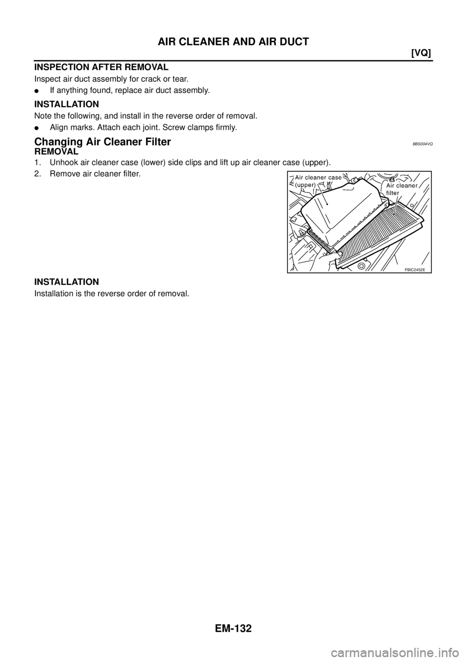
Changing Air Cleaner FilterBBS004VQ
REMOVAL
1. Unhook air cleaner case (lower) side clips and lift up air cleaner case (upper).
2. Remove air cleaner filter.
INSTALLATION
Installation is the reverse order of removal.
PBIC2452E
Page 2242 of 3502
![NISSAN TEANA 2003 Service Manual EM-134
[VQ]
INTAKE MANIFOLD COLLECTOR
�Refer to GI-10, "Components" for symbol marks in the figure.
NOTE:
The figure illustrates VQ35DE as an example. Each part form of VQ23DE is different from VQ](/manual-img/5/57392/w960_57392-2241.png "NISSAN TEANA 2003 Service Manual EM-134
[VQ]
INTAKE MANIFOLD COLLECTOR
�Refer to GI-10, \"Components\" for symbol marks in the figure.
NOTE:
The figure illustrates VQ35DE as an example. Each part form of VQ23DE is different from VQ")
EM-134
[VQ]
INTAKE MANIFOLD COLLECTOR
�Refer to GI-10, "Components" for symbol marks in the figure.
NOTE:
The figure illustrates VQ35DE as an example. Each part form of VQ23DE is different from VQ35DE for differ-
ence of port diameter and so forth. Only portions which structures (components) differ are illustrated.
REMOVAL
WARNING:
To avoid the danger of being scalded, do not drain engine coolant when engine is hot.
NOTE:
Show VQ35DE as an example unless the figure includes specification.
1. Remove engine cover.
CAUTION:
Be careful not to damage or scratch engine cover.
2. Remove air cleaner case (upper) with mass air flow sensor and air duct assembly. Refer to EM-131, "
AIR
CLEANER AND AIR DUCT" .
3. Drain engine coolant, or when water hoses are disconnected, attach plug to prevent engine coolant leak-
age. Refer to CO-34, "
Changing Engine Coolant" .
CAUTION:
Perform this step when engine is cold.
4. Remove electric throttle control actuator as follows:
a. Disconnect harness connector.
b. Loosen mounting bolts in the reverse order as shown in the fig-
ure.
CAUTION:
�Handle carefully to avoid any shock to electric throttle
control actuator.
�Do not disassemble.
5. Disconnect water hoses from intake manifold collector (upper).
�When engine coolant is not drained from radiator, attach plug to water hoses to prevent engine coolant
leakage.
PBIC2454E
KBIA2007J
Page 2243 of 3502
INTAKE MANIFOLD COLLECTOR
EM-135
[VQ]
C
D
E
F
G
H
I
J
K
L
MA
EM
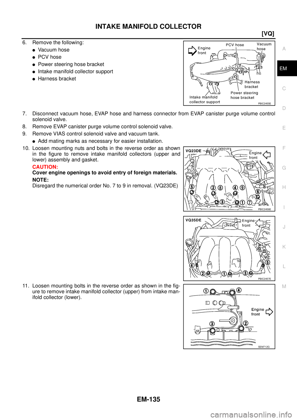
6. Remove the following:
�Va c u u m h o s e
�PCV hose
�Power steering hose bracket
�Intake manifold collector support
�Harness bracket
7. Disconnect vacuum hose, EVAP hose and harness connector from EVAP canister purge volume control
solenoid valve.
8. Remove EVAP canister purge volume control solenoid valve.
9. Remove VIAS control solenoid valve and vacuum tank.
�Add mating marks as necessary for easier installation.
10. Loosen mounting nuts and bolts in the reverse order as shown
in the figure to remove intake manifold collectors (upper and
lower) assembly and gasket.
CAUTION:
Cover engine openings to avoid entry of foreign materials.
NOTE:
Disregard the numerical order No. 7 to 9 in removal. (VQ23DE)
11. Loosen mounting bolts in the reverse order as shown in the fig-
ure to remove intake manifold collector (upper) from intake man-
ifold collector (lower).
PBIC2455E
PBIC2456E
PBIC2457E
SEM712G
Page 2244 of 3502
EM-136
[VQ]
INTAKE MANIFOLD COLLECTOR
12. Loosen mounting bolts in the reverse order as shown in the fig-
ure to remove power valve from intake manifold collector
(lower).
INSPECTION AFTER REMOVAL
Surface Distortion
�Check the surface distortion of intake manifold collector (lower)
with straightedge and feeler gauge.
�If it exceeds the limit, replace intake manifold collector (lower).
INSTALLATION
Note the following, and install in the reverse order of removal.
NOTE:
Show VQ35DE as an example unless the figure includes specification.
Power Valve
Tighten mounting bolts in numerical order as shown in the figure.
Intake Manifold Collector (Upper)
Tighten mounting bolts in numerical order as shown in the figure.
SEM714G
Limit : 0.1 mm (0.004 in)
PBIC1168E
SEM714G
SEM712G
Page 2246 of 3502
EM-138
[VQ]
INTAKE MANIFOLD
INTAKE MANIFOLDPFP:14003
Removal and InstallationBBS004VS
NOTE:
Figure is shown as an example VQ35DE. VQ23DE has a different port shape, bolt hole for intake manifold collector (lower) installation
and stud bolt position.
REMOVAL
1. Release fuel pressure. Refer to EC-392, "FUEL PRESSURE RELEASE" .
2. Remove intake manifold collectors (upper and lower). Refer to EM-133, "
INTAKE MANIFOLD COLLEC-
TOR" .
3. Remove fuel tube and fuel injector assembly. Refer to EM-155, "
FUEL INJECTOR AND FUEL TUBE" .
4. Loosen mounting nuts and bolts in the reverse order as shown
in the figure to remove intake manifold.
5. Remove gaskets.
1. Intake manifold 2. Gasket
PBIC2458E
PBIC2459E
PBIC2460E
![NISSAN TEANA 2003 Service Manual CYLINDER BLOCK
EM-85
[QR]
C
D
E
F
G
H
I
J
K
L
MA
EM
a. Using snap ring pliers, remove snap ring.
b. Heat piston to 60 to 70°C (140 to 158°F) with industrial use drier
or equivalent.
c. Push out pi](/manual-img/5/57392/w960_57392-2192.png "NISSAN TEANA 2003 Service Manual CYLINDER BLOCK
EM-85
[QR]
C
D
E
F
G
H
I
J
K
L
MA
EM
a. Using snap ring pliers, remove snap ring.
b. Heat piston to 60 to 70°C (140 to 158°F) with industrial use drier
or equivalent.
c. Push out pi")
![NISSAN TEANA 2003 Service Manual EM-136
[VQ]
INTAKE MANIFOLD COLLECTOR
12. Loosen mounting bolts in the reverse order as shown in the fig-
ure to remove power valve from intake manifold collector
(lower).
INSPECTION AFTER REMOVAL
S](/manual-img/5/57392/w960_57392-2243.png "NISSAN TEANA 2003 Service Manual EM-136
[VQ]
INTAKE MANIFOLD COLLECTOR
12. Loosen mounting bolts in the reverse order as shown in the fig-
ure to remove power valve from intake manifold collector
(lower).
INSPECTION AFTER REMOVAL
S")
![NISSAN TEANA 2003 Service Manual EM-138
[VQ]
INTAKE MANIFOLD
INTAKE MANIFOLDPFP:14003
Removal and InstallationBBS004VS
NOTE:
Figure is shown as an example VQ35DE. VQ23DE has a different port shape, bolt hole for intake manifold col](/manual-img/5/57392/w960_57392-2245.png "NISSAN TEANA 2003 Service Manual EM-138
[VQ]
INTAKE MANIFOLD
INTAKE MANIFOLDPFP:14003
Removal and InstallationBBS004VS
NOTE:
Figure is shown as an example VQ35DE. VQ23DE has a different port shape, bolt hole for intake manifold col")