Page 2247 of 3502
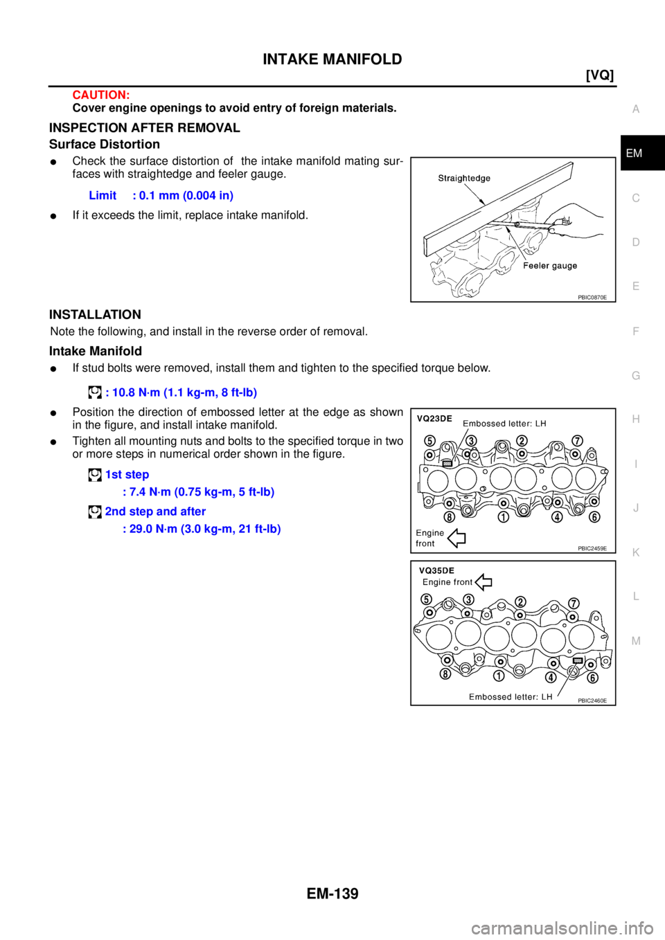
INTAKE MANIFOLD
EM-139
[VQ]
C
D
E
F
G
H
I
J
K
L
MA
EM
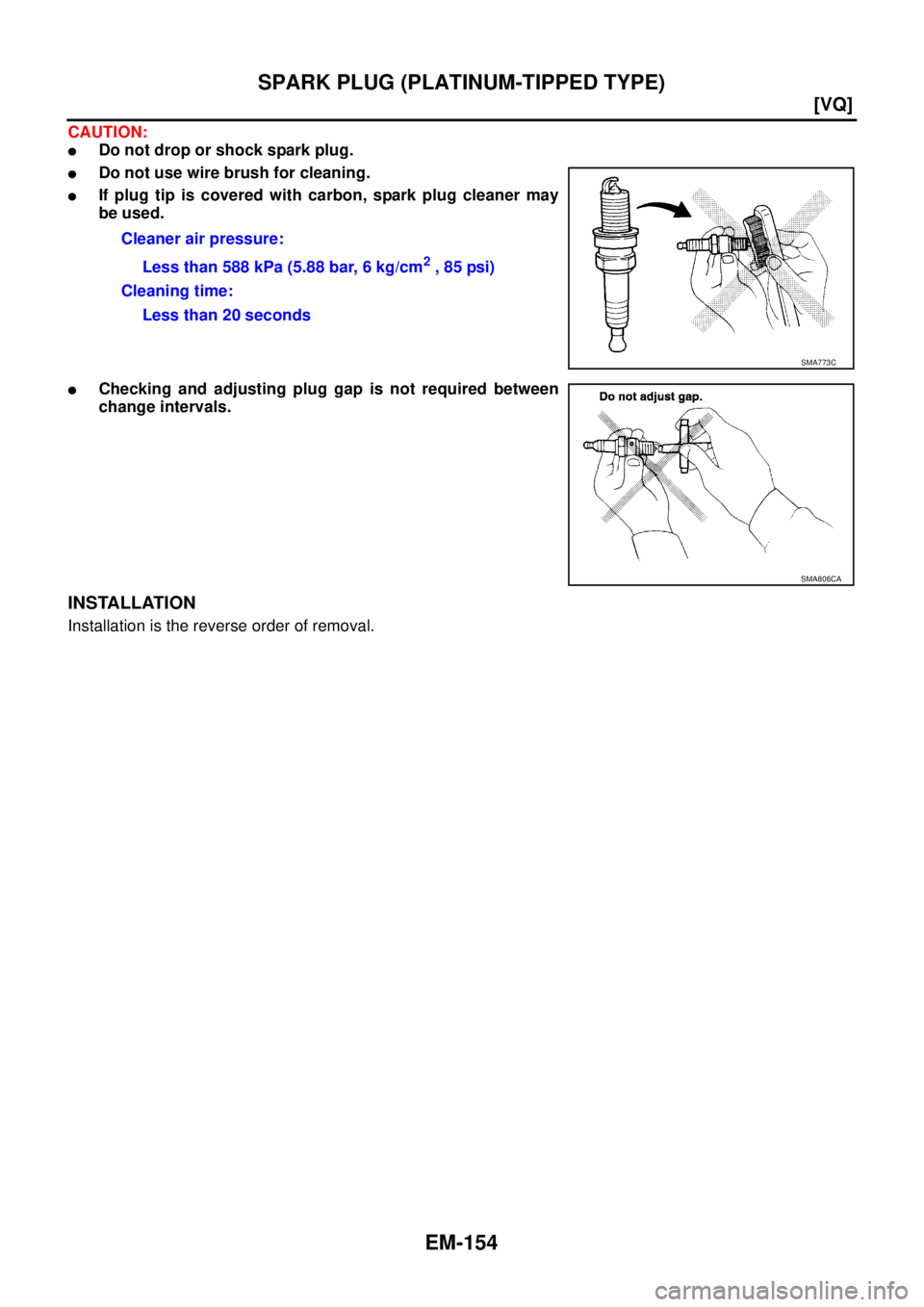
CAUTION:
Cover engine openings to avoid entry of foreign materials.
INSPECTION AFTER REMOVAL
Surface Distortion
�Check the surface distortion of the intake manifold mating sur-
faces with straightedge and feeler gauge.
�If it exceeds the limit, replace intake manifold.
INSTALLATION
Note the following, and install in the reverse order of removal.
Intake Manifold
�If stud bolts were removed, install them and tighten to the specified torque below.
�Position the direction of embossed letter at the edge as shown
in the figure, and install intake manifold.
�Tighten all mounting nuts and bolts to the specified torque in two
or more steps in numerical order shown in the figure.Limit : 0.1 mm (0.004 in)
PBIC0870E
: 10.8 N·m (1.1 kg-m, 8 ft-lb)
1st step
: 7.4 N·m (0.75 kg-m, 5 ft-lb)
2nd step and after
: 29.0 N·m (3.0 kg-m, 21 ft-lb)
PBIC2459E
PBIC2460E
Page 2249 of 3502
![NISSAN TEANA 2003 Service Manual EXHAUST MANIFOLD AND THREE WAY CATALYST
EM-141
[VQ]
C
D
E
F
G
H
I
J
K
L
MA
EM
3. Remove exhaust front tube mounting bracket and then remove exhaust front tube. Refer to EX-2,
"EXHAUST SYSTEM" .
4. R](/manual-img/5/57392/w960_57392-2248.png "NISSAN TEANA 2003 Service Manual EXHAUST MANIFOLD AND THREE WAY CATALYST
EM-141
[VQ]
C
D
E
F
G
H
I
J
K
L
MA
EM
3. Remove exhaust front tube mounting bracket and then remove exhaust front tube. Refer to EX-2,
\"EXHAUST SYSTEM\" .
4. R")
EXHAUST MANIFOLD AND THREE WAY CATALYST
EM-141
[VQ]
C
D
E
F
G
H
I
J
K
L
MA
EM
3. Remove exhaust front tube mounting bracket and then remove exhaust front tube. Refer to EX-2,
"EXHAUST SYSTEM" .
4. Remove heat insulator.
5. Disconnect harness connector and remove heated oxygen sen-
sor 1 on both banks with heated oxygen sensor wrench (SST).
�Put marks to identify installation positions of each heated oxy-
gen sensor 1.
CAUTION:
�Be careful not to damage heated oxygen sensor 1.
�Discard any heated oxygen sensor 1 which has been
dropped onto a hard surface such as a concrete floor;
replace with a new sensor.
NOTE:
Figure is shown as an example of left bank.
6. Disconnect harness connector and remove heated oxygen sen-
sor 2 on both banks with heated oxygen sensor wrench (SST).
�Put marks to identify installation positions of each heated oxy-
gen sensor 2.
CAUTION:
�Be careful not to damage heated oxygen sensor 2.
�Discard any heated oxygen sensor 2 which has been
dropped onto a hard surface such as a concrete floor;
replace with a new sensor.
7. Remove exhaust manifold covers (right and left banks) and three way catalyst covers.
8. Remove mounting bolts in the reverse order as shown in the fig-
ure to remove three way catalyst supports (right and left banks).
9. Remove three way catalysts (right and left banks) by loosening bolts first and then removing nuts.
CAUTION:
Handle carefully to avoid any shock to three way catalyst.
PBIC2503E
PBIC2462E
PBIC2544E
PBIC2463E
Page 2250 of 3502
EM-142
[VQ]
EXHAUST MANIFOLD AND THREE WAY CATALYST
10. Loosen mounting nuts in the reverse order as shown in the fig-
ure to remove exhaust manifolds (right and left banks).
11. Remove gaskets.
CAUTION:
Cover engine openings to avoid entry of foreign materials.
INSPECTION AFTER REMOVAL
Surface Distortion
�Check the surface distortion of the exhaust manifold mating sur-
faces with straightedge and feeler gauge.
�If it exceeds the limit, replace exhaust manifold.
INSTALLATION
Note the following, and install in the reverse order of removal.
Exhaust Manifold Gasket
Install in the direction indicated in the figure.
PBIC2464E
Limit : 0.3 mm (0.012 in)
PBIC1173E
KBIA1051E
Page 2254 of 3502
![NISSAN TEANA 2003 Service Manual EM-146
[VQ]
OIL PAN AND OIL STRAINER
CAUTION:
�Perform this step when engine is cold.
�Do not spill engine coolant on drive belts.
3. Remove the following:
�Engine cover; Refer to EM-133, "INTAKE MA](/manual-img/5/57392/w960_57392-2253.png "NISSAN TEANA 2003 Service Manual EM-146
[VQ]
OIL PAN AND OIL STRAINER
CAUTION:
�Perform this step when engine is cold.
�Do not spill engine coolant on drive belts.
3. Remove the following:
�Engine cover; Refer to EM-133, \"INTAKE MA")
EM-146
[VQ]
OIL PAN AND OIL STRAINER
CAUTION:
�Perform this step when engine is cold.
�Do not spill engine coolant on drive belts.
3. Remove the following:
�Engine cover; Refer to EM-133, "INTAKE MANIFOLD COLLECTOR" .
�Splash guard (RH)
�Exhaust front tube; Refer to EX-2, "EXHAUST SYSTEM" .
�Drive belts; Refer to EM-128, "DRIVE BELTS" .
4. Remove A/C compressor with piping connected, and temporarily secure it to aside. Refer to ATC-133,
"Components" .
5. Remove three way catalysts (right and left banks) from exhaust manifolds (right and left banks). Refer to
EM-140, "
EXHAUST MANIFOLD AND THREE WAY CATALYST" .
6. Remove oil pressure switch. Refer to LU-20, "
OIL PRESSURE CHECK" .
7. Remove crankshaft position sensor (POS).
CAUTION:
�Handle carefully to avoid dropping and shocks.
�Do not disassemble.
�Do not allow metal powder to adhere to magnetic part at sensor tip.
�Do not place sensor in a location where it is exposed to magnetism.
8. Remove oil filter. Refer to LU-22, "
OIL FILTER" .
9. Remove oil cooler and water pipes (VQ35DE). Refer to LU-23, "
OIL COOLER (VQ35DE)" .
10. Remove oil pan (lower) as follows:
a. Loosen mounting bolts in the reverse order as shown in the fig-
ure.
b. Insert seal cutter (SST) between oil pan (lower) and oil pan
(upper).
CAUTION:
�Be careful not to damage the mating surfaces.
�Do not insert screwdriver, this will damage the mating
surfaces.
c. Slide seal cutter by tapping on the side of the tool with hammer.
Remove oil pan (lower).
PBIC0782E
SEM365ED
Page 2255 of 3502
OIL PAN AND OIL STRAINER
EM-147
[VQ]
C
D
E
F
G
H
I
J
K
L
MA
EM
11. Remove oil strainer.
12. Remove oil pan (upper) as follows:
a. Remove transaxle joint bolts which pierce oil pan (upper).
b. Loosen mounting bolts in the reverse order as shown in the fig-
ure.
c. Insert suitable tool into the notch of oil pan (upper) as shown (1).
Pry off oil pan (upper) by moving tool up and down as shown (2)
to remove oil pan (upper).
PBIC1766E
SEM949G
PBIC1636E
SEM155F
Page 2258 of 3502
![NISSAN TEANA 2003 Service Manual EM-150
[VQ]
OIL PAN AND OIL STRAINER
a. Use scraper to remove old liquid gasket from mating surfaces.
�Also remove old liquid gasket from mating surface of oil pan
(upper).
�Remove old liquid gasket](/manual-img/5/57392/w960_57392-2257.png "NISSAN TEANA 2003 Service Manual EM-150
[VQ]
OIL PAN AND OIL STRAINER
a. Use scraper to remove old liquid gasket from mating surfaces.
�Also remove old liquid gasket from mating surface of oil pan
(upper).
�Remove old liquid gasket")
EM-150
[VQ]
OIL PAN AND OIL STRAINER
a. Use scraper to remove old liquid gasket from mating surfaces.
�Also remove old liquid gasket from mating surface of oil pan
(upper).
�Remove old liquid gasket from the bolt holes and thread.
CAUTION:
Do not scratch or damage the mating surfaces when clean-
ing off old liquid gasket.
b. Apply a continuous bead of liquid gasket with tube presser [SST:
WS39930000] to oil pan (lower) as shown in the figure.
Use Genuine Liquid Gasket or equivalent.
CAUTION:
Attaching should be done within 5 minutes after coating.
c. Install oil pan (lower).
�Tighten mounting bolts in numerical order as shown in the fig-
ure.
4. Install oil pan drain plug.
�Refer to the figure of components of former page for installation direction of drain plug washer. Refer to
EM-145, "
Removal and Installation" .
5. Install in the reverse order of removal after this step.
NOTE:
At least 30 minutes after oil pan is installed, pour engine oil.
INSPECTION AFTER INSTALLATION
1. Check the engine oil level and adjust engine oil. Refer to LU-19, "ENGINE OIL" .
2. Start engine, and make sure there is no leak of engine oil.
SEM958F
PBIC2647E
PBIC0782E
Page 2260 of 3502
EM-152
[VQ]
IGNITION COIL
IGNITION COILPFP:22448
Removal and InstallationBBS004VV
REMOVAL
1. Remove engine cover. Refer to EM-133, "INTAKE MANIFOLD COLLECTOR" .
2. Remove intake manifold collectors (upper and lower). (At the right bank side, remove ignition coil) Refer to
EM-133, "
INTAKE MANIFOLD COLLECTOR" .
3. Move aside harness, harness bracket, and hoses located above ignition coil.
4. Disconnect harness connector from ignition coil.
5. Remove ignition coil.
CAUTION:
Do not drop or shock it.
INSTALLATION
Installation is the reverse order of removal.
1. Ignition coil 2. Spark plug 3. Rocker cover
A. Left bank
PBIC4359E
Page 2262 of 3502
EM-154
[VQ]
SPARK PLUG (PLATINUM-TIPPED TYPE)
CAUTION:
�Do not drop or shock spark plug.
�Do not use wire brush for cleaning.
�If plug tip is covered with carbon, spark plug cleaner may
be used.
�Checking and adjusting plug gap is not required between
change intervals.
INSTALLATION
Installation is the reverse order of removal.Cleaner air pressure:
Less than 588 kPa (5.88 bar, 6 kg/cm
2 , 85 psi)
Cleaning time:
Less than 20 seconds
SMA773C
SMA806CA
![NISSAN TEANA 2003 Service Manual EM-142
[VQ]
EXHAUST MANIFOLD AND THREE WAY CATALYST
10. Loosen mounting nuts in the reverse order as shown in the fig-
ure to remove exhaust manifolds (right and left banks).
11. Remove gaskets.
CAU](/manual-img/5/57392/w960_57392-2249.png "NISSAN TEANA 2003 Service Manual EM-142
[VQ]
EXHAUST MANIFOLD AND THREE WAY CATALYST
10. Loosen mounting nuts in the reverse order as shown in the fig-
ure to remove exhaust manifolds (right and left banks).
11. Remove gaskets.
CAU")
![NISSAN TEANA 2003 Service Manual OIL PAN AND OIL STRAINER
EM-147
[VQ]
C
D
E
F
G
H
I
J
K
L
MA
EM
11. Remove oil strainer.
12. Remove oil pan (upper) as follows:
a. Remove transaxle joint bolts which pierce oil pan (upper).
b. Loose](/manual-img/5/57392/w960_57392-2254.png "NISSAN TEANA 2003 Service Manual OIL PAN AND OIL STRAINER
EM-147
[VQ]
C
D
E
F
G
H
I
J
K
L
MA
EM
11. Remove oil strainer.
12. Remove oil pan (upper) as follows:
a. Remove transaxle joint bolts which pierce oil pan (upper).
b. Loose")
![NISSAN TEANA 2003 Service Manual EM-152
[VQ]
IGNITION COIL
IGNITION COILPFP:22448
Removal and InstallationBBS004VV
REMOVAL
1. Remove engine cover. Refer to EM-133, "INTAKE MANIFOLD COLLECTOR" .
2. Remove intake manifold collectors](/manual-img/5/57392/w960_57392-2259.png "NISSAN TEANA 2003 Service Manual EM-152
[VQ]
IGNITION COIL
IGNITION COILPFP:22448
Removal and InstallationBBS004VV
REMOVAL
1. Remove engine cover. Refer to EM-133, \"INTAKE MANIFOLD COLLECTOR\" .
2. Remove intake manifold collectors")