Page 235 of 3502
ON-VEHICLE SERVICE
AT-227
D
E
F
G
H
I
J
K
L
MA
B
AT
Bolt length, number and location:
12. Remove control valve assembly from transaxle case.
CAUTION:
Be careful not to drop manual valve and servo release accumulator return spring.
13. Remove manual valve from control valve assembly.
CAUTION:
Be careful not drop manual valve.
14. Remove O-ring from terminal body.
15. Disassemble and inspect control valve assembly if necessary.
Refer to AT- 2 8 0 , "
Control Valve Assembly" , AT- 2 8 9 , "Control
Valve Upper Body" and AT- 2 9 3 , "Control Valve Lower Body" .
16. Remove servo release accumulator piston and N-D accumulator
piston by applying compressed air if necessary.
CAUTION:
Hold each piston with a lint-free paper.
Bolt symbol A B C
Bolt length “ ” mm (in)
40.0 mm
(1.575 in)33.0 mm
(1.299 in)43.5 mm
(1.713 in)
Number of bolts 5 6 2
AAT260A
SCIA3150E
SCIA4854E
Page 237 of 3502
 and
length (L
2")
ON-VEHICLE SERVICE
AT-229
D
E
F
G
H
I
J
K
L
MA
B
AT
�Check each return spring, and replace if damaged, deformed or
worn. Refer to AT- 3 6 5 , "
Accumulator" for free length (L1 ) and
length (L
2 ).
(1): Return spring (Servo release accumulator)
(2): Return spring (N-D accumulator)
CAUTION:
Do not remove spring retainer (3).
Installation
Note the following, and install in the reverse order of removal.
�Set manual shaft in “N” position, then align manual plate with
groove in manual valve.
�After installing control valve assembly to transaxle, make sure
that select lever can be moved to all positions.
�After completing installation, check for leakage, and A/T fluid
level. Refer to AT- 1 4 , "
Checking A/T Fluid" .
CAUTION:
�Completely remove all moisture, oil and old gasket, etc.
from the oil pan gasket mounting surface of transaxle case
and oil pan.
�Do not reuse O-rings, lip seals, oil pan gasket and oil pan
fitting bolts.
�Apply ATF to manual valve, O-rings, lip seals and sliding surfaces transaxle case.
SCIA6955E
SAT497H
Page 252 of 3502

AT-244
TRANSAXLE ASSEMBLY
20. Remove fluid cooler tubes.
INSPECTION
Installation and Inspection of Torque Converter
�After inserting a torque converter to a A/T, be sure to check
dimension “A” to ensure it is within the reference value limit.
INSTALLATION
Install removed parts in the reverse order of the removal, while paying attention to the following work.
�When installing transaxle to engine, attach fixing bolts in accordance with the following standard.
QR20DE engine models
VQ23DE engine models
SCIA7921E
Dimension “A”
For QR20DE engine models
: 19.0 mm (0.75 in) or more
For VQ23DE engine models
: 14.0 mm (0.55 in) or more
SCIA5621E
Bolt No. 1 2 3 4 5 6
Number of bolts 4 1 1 2 2 1
Bolt length
“ ”mm (in)49
(1.93) 40
(1.57) 45
(1.77)40
(1.57)30
(1.18)45
(1.77)
Tightening torque
N·m (kg-m, ft-lb)75
(7.7, 55)35
(3.6, 26)75
(7.7, 55)43 (4.4, 32)35
(3.6, 26)
SCIA4358E
Bolt No. 1 2 3 4
Number of bolts 1 4 4 1
Bolt length
“ ”mm (in)118 (4.65) 52 (2.05) 40 (1.57) 65 (2.56)
Tightening torque
N·m (kg-m, ft-lb)74 (7.5, 55) 75 (7.7, 55) 47 (4.8, 35) 75 (7.7, 55)
SCIA4359E
Page 265 of 3502
DISASSEMBLY
AT-257
D
E
F
G
H
I
J
K
L
MA
B
AT
c. Remove control valve assembly fitting bolts A , B and C .
Bolt length, number and location:
d. Remove control valve assembly from transaxle case.
CAUTION:
Be careful not to drop manual valve.
17. Remove manual valve from control valve assembly.
�Check the sliding surfaces of manual valve and valve body,
and replace if damage or dented.
CAUTION:
Be careful not to drop manual valve.
18. Remove O-ring from terminal body.
19. Remove return spring from servo release accumulator piston.
Bolt symbol A B C
Bolt length “ ” mm (in)
40.0
(1.575)33.0
(1.299)43.5
(1.713)
Number of bolts 5 6 2
AAT260A
SAT005F
SCIA3477E
Page 267 of 3502
DISASSEMBLY
AT-259
D
E
F
G
H
I
J
K
L
MA
B
AT
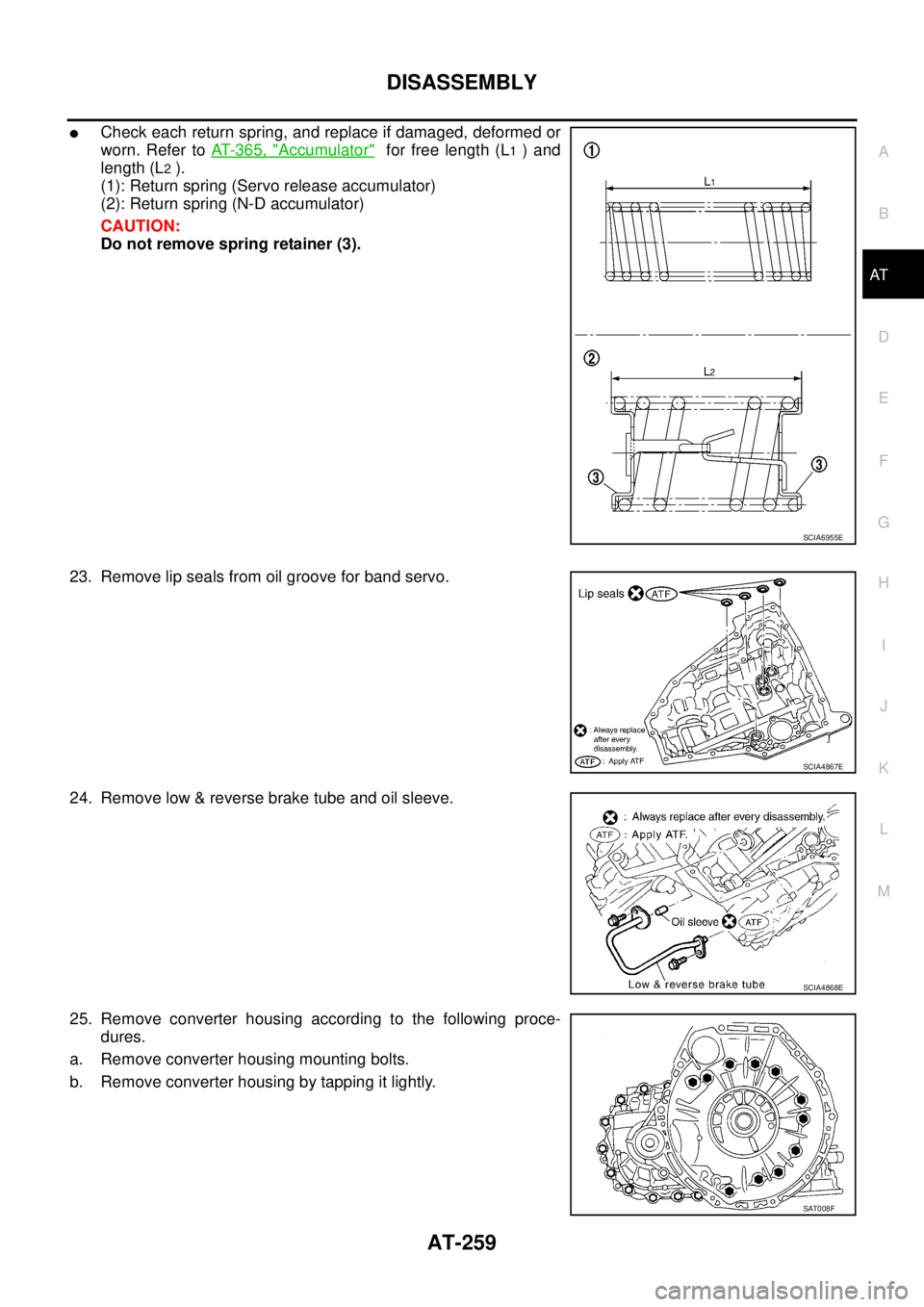
�Check each return spring, and replace if damaged, deformed or
worn. Refer to AT- 3 6 5 , "
Accumulator" for free length (L1 ) and
length (L
2 ).
(1): Return spring (Servo release accumulator)
(2): Return spring (N-D accumulator)
CAUTION:
Do not remove spring retainer (3).
23. Remove lip seals from oil groove for band servo.
24. Remove low & reverse brake tube and oil sleeve.
25. Remove converter housing according to the following proce-
dures.
a. Remove converter housing mounting bolts.
b. Remove converter housing by tapping it lightly.
SCIA6955E
SCIA4867E
SCIA4868E
SAT008F
Page 289 of 3502
REPAIR FOR COMPONENT PARTS
AT-281
D
E
F
G
H
I
J
K
L
MA
B
AT
DISASSEMBLY
Disassemble control valve upper, inter and lower bodies.
Bolt length, number and location:
f: Reamer bolt and nut.
1. Remove bolts a , d , reamer bolt f and nut , and remove oil
strainer from control valve assembly.
2. Remove bolts a, c and g , and remove solenoid valve assembly
and line pressure solenoid valve from control valve assembly.
Bolt symbolabcde f g
Bolt length “ ” mm (in)
13.5
(0.531)58.0
(2.283) 40.0
(1.575)66.0
(2.598)33.0
(1.299)78.0
(3.071)18.0
(0.709)
Number of bolts 6 3 6 11 2 2 1
SCIA4974E
SCIA3484E
SCIA4438E
Page 293 of 3502
REPAIR FOR COMPONENT PARTS
AT-285
D
E
F
G
H
I
J
K
L
MA
B
AT
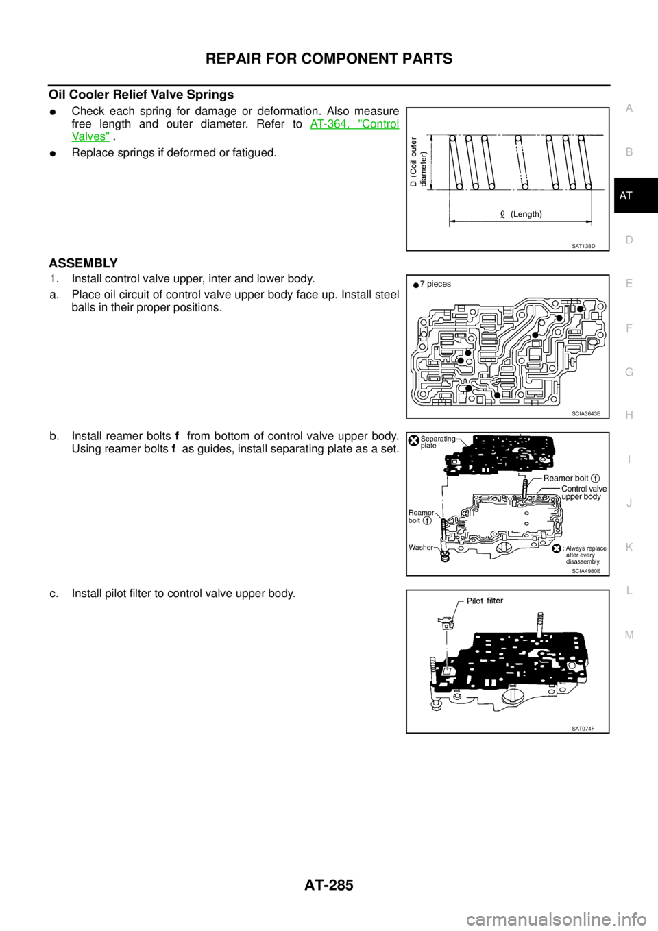
Oil Cooler Relief Valve Springs
�Check each spring for damage or deformation. Also measure
free length and outer diameter. Refer to AT- 3 6 4 , "
Control
Va l v e s" .
�Replace springs if deformed or fatigued.
ASSEMBLY
1. Install control valve upper, inter and lower body.
a. Place oil circuit of control valve upper body face up. Install steel
balls in their proper positions.
b. Install reamer bolts f from bottom of control valve upper body.
Using reamer bolts f as guides, install separating plate as a set.
c. Install pilot filter to control valve upper body.
SAT138D
SCIA3643E
SCIA4980E
SAT074F
Page 295 of 3502
REPAIR FOR COMPONENT PARTS
AT-287
D
E
F
G
H
I
J
K
L
MA
B
AT
2. Install O-rings (1) to solenoid valves and terminal body.
3. Install and tighten bolts.
Bolt length, number and location:
f: Reamer bolt and nut.
a. Install and tighten bolts b and nut f to specified torque.
SCIA7819E
Bolt symbolabcde f g
Bolt length “ ” mm (in)
13.5
(0.531)58.0
(2.283) 40.0
(1.575)66.0
(2.598)33.0
(1.299)78.0
(3.071)18.0
(0.709)
Number of bolts 6 3 6 11 2 2 1
Tightening torque
N·m (kg-m, in-lb)7.8 (0.80, 69)4.0
(0.41, 35)7.8 (0.80, 69)
SCIA4974E
: 7.8 N·m (0.80 kg-m, 69 in-lb)
SCIA4437E


 to solenoid valves and terminal body.
3. Install and tighten bolts.
Bolt length, number and location:
f: Reamer bol")