Page 299 of 3502

REPAIR FOR COMPONENT PARTS
AT-291
D
E
F
G
H
I
J
K
L
MA
B
AT
c. Place mating surface of valve body face down, and remove
internal parts.
CAUTION:
�If a valve is hard to remove, place valve body face down
and lightly tap it with a soft hammer.
�Be careful not to drop or damage valves and sleeves.
INSPECTION
Valve Springs
�Measure free length and outer diameter of each valve spring.
Also check for damage or deformation. Refer to AT- 3 6 4 , "
Con-
trol Valves" .
�Replace valve springs if deformed or fatigued.
Control Valves
Check sliding surfaces of valves, sleeves and plugs. Replace if necessary.
ASSEMBLY
CAUTION:
�Apply ATF to all components before installation.
�Lay control valve body down when installing valves. Do not
stand control valve body upright.
�Lubricate control valve body and all valves with ATF. Install con-
trol valves by sliding them carefully into their bores.
CAUTION:
�Install each control valve one by one.
�Install control valves after checking, because some of
them are similar.
�Be careful not to scratch or damage valve body.
SAT137D
SAT138D
SAT139D
SAT140DA
Page 300 of 3502
AT-292
REPAIR FOR COMPONENT PARTS
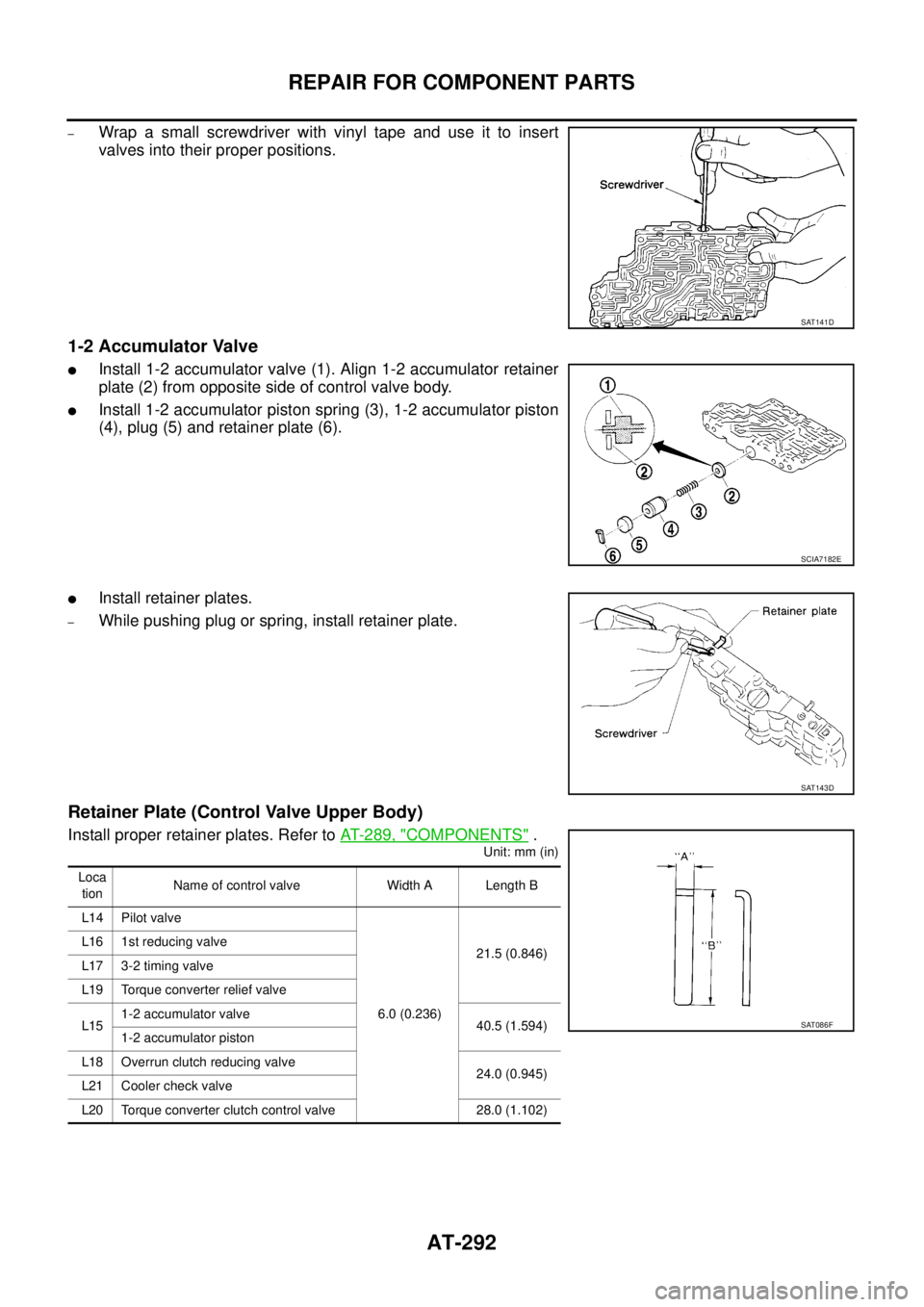
–Wrap a small screwdriver with vinyl tape and use it to insert
valves into their proper positions.
1-2 Accumulator Valve
�Install 1-2 accumulator valve (1). Align 1-2 accumulator retainer
plate (2) from opposite side of control valve body.
�Install 1-2 accumulator piston spring (3), 1-2 accumulator piston
(4), plug (5) and retainer plate (6).
�Install retainer plates.
–While pushing plug or spring, install retainer plate.
Retainer Plate (Control Valve Upper Body)
Install proper retainer plates. Refer to AT- 2 8 9 , "COMPONENTS" .
Unit: mm (in)
SAT141D
SCIA7182E
SAT143D
Loca
tionName of control valve Width A Length B
L14 Pilot valve
6.0 (0.236)21.5 (0.846) L16 1st reducing valve
L17 3-2 timing valve
L19 Torque converter relief valve
L151-2 accumulator valve
40.5 (1.594)
1-2 accumulator piston
L18 Overrun clutch reducing valve
24.0 (0.945)
L21 Cooler check valve
L20 Torque converter clutch control valve 28.0 (1.102)
SAT086F
Page 302 of 3502

AT-294
REPAIR FOR COMPONENT PARTS
DISASSEMBLY
Remove valves at retainer plate.
For removal procedures, refer to AT- 2 9 0 , "
DISASSEMBLY" .
INSPECTION
Valve Springs
�Check each valve spring for damage or deformation. Also mea-
sure free length and outer diameter. Refer to AT- 3 6 4 , "
Control
Va l v e s" .
�Replace valve springs if deformed or fatigued.
Control Valves
Check sliding surfaces of control valves, sleeves and plugs for damage. Replace if necessary.
ASSEMBLY
CAUTION:
�Apply ATF to all components before installation.
�Lay control valve body down when installing valves. Do not
stand control valve body upright.
1. Retainer plate 2. Pressure modifier piston spring 3. Pressure modifier piston
4. Parallel pin 5. Sleeve 6. Pressure modifier valve spring
7. Pressure modifier valve 8. Control valve lower body 9. Manual valve
10. Pressure regulator valve 11. Pressure regulator valve spring 12. Spring seat
13. Plug 14. Retainer plate 15. Sleeve
16. Overrun clutch control valve spring 17. Overrun clutch control valve 18. Plug
19. Retainer plate 20. Accumulator control valve spring 21. Accumulator control valve
22. Plug 23. Retainer plate 24. Retainer plate
25. Shift valve A spring 26. Shift valve A 27. Retainer plate
28. Plug 29. Shuttle plug 30. Shuttle valve spring
31. Shuttle valve 32. Shift valve B spring 33. Shift valve B
34. Plug 35. Retainer plate
SCIA4978E
SAT138D
SAT139D
Page 303 of 3502
REPAIR FOR COMPONENT PARTS
AT-295
D
E
F
G
H
I
J
K
L
MA
B
AT
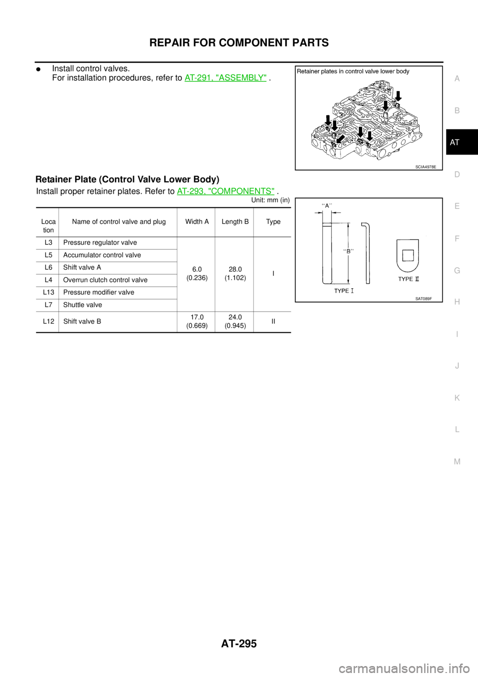
�Install control valves.
For installation procedures, refer to AT- 2 9 1 , "
ASSEMBLY" .
Retainer Plate (Control Valve Lower Body)
Install proper retainer plates. Refer to AT- 2 9 3 , "COMPONENTS" .
Unit: mm (in)
SCIA4978E
Loca
tionName of control valve and plug Width A Length B Type
L3 Pressure regulator valve
6.0
(0.236)28.0
(1.102)I L5 Accumulator control valve
L6 Shift valve A
L4 Overrun clutch control valve
L13 Pressure modifier valve
L7 Shuttle valve
L12 Shift valve B17.0
(0.669)24.0
(0.945)II
SAT089F
Page 339 of 3502
REPAIR FOR COMPONENT PARTS
AT-331
D
E
F
G
H
I
J
K
L
MA
B
AT
9. Remove spring retainer, O/D servo return spring, band servo
thrust washer and band servo piston stem from band servo pis-
ton.
10. Remove O-rings from servo piston retainer.
11. Remove D-rings from band servo piston.
INSPECTION
Pistons, Retainers and Piston Stem
Check frictional surfaces for abnormal wear or damage. Replace if necessary.
Return Springs
�Check each return spring for deformation or damage. Also mea-
sure free length and outer diameter. Refer to AT- 3 6 8 , "
Band
Servo" .
�Replace spring if deformed or fatigued.
SCIA4746E
SCIA3671E
SCIA3688E
AAT884
Page 367 of 3502

ASSEMBLY
AT-359
D
E
F
G
H
I
J
K
L
MA
B
AT
c. Set manual shaft in “N” position.
d. Install control valve assembly on transaxle case while aligning
manual valve with manual plate.
e. Pass terminal cord assembly through transaxle case and install
terminal body on transaxle case by pushing it.
f. Install snap ring to terminal body.
CAUTION:
Do not expand snap ring excessively.
g. Tighten control valve assembly fixing bolts A , B and C to the specified torque. Refer to AT- 2 4 6 , "
Compo-
nents" .
Bolt length, number and location:
21. Install oil pan according to the following procedures.
a. Attach a magnets to oil pan.
b. Install oil pan gasket on transaxle case.
CAUTION:
�Do not reuse oil pan gasket.
�Completely remove all moisture, oil and old gasket, etc. from the transaxle case and oil pan
mounting surfaces.
c. Install oil pan on transaxle case.
d. Tighten oil pan fitting bolts to the specified torque. Refer to AT- 2 4 6 , "
Components" .
SAT094J
SCIA4866E
Bolt symbol A B C
Bolt length “ ” mm (in)
40.0
(1.575)33.0
(1.299)43.5
(1.713)
Number of bolts 5 6 2
AAT260A
Page 372 of 3502

OUTER DIAMETER OF SNAP RINGS
Unit: mm (in)
Control ValvesBCS001P2
CONTROL VALVE RETURN SPRINGS
For QR20DE Engine Models
Unit: mm (in) Location Outer diam")
AT-364
SERVICE DATA AND SPECIFICATIONS (SDS)
OUTER DIAMETER OF SNAP RINGS
Unit: mm (in)
Control ValvesBCS001P2
CONTROL VALVE RETURN SPRINGS
For QR20DE Engine Models
Unit: mm (in) Location Outer diameter
1 144.8 (5.701)
2 173.8 (6.843)
3 133.9 (5.272)
4 119.1 (4.689)
5 150 (5.91)
6 182.8 (7.197)
PartsItem
Free length Outer diameter
Upper bodyL14 Pilot valve spring 38.98 (1.535) 8.9 (0.350)
L151-2 accumulator valve spring 20.5 (0.807) 6.95 (0.274)
1-2 accumulator piston spring 55.66 (2.191) 19.6 (0.772)
L16 1st reducing valve spring 27.0 (1.062) 7.0 (0.276)
L17 3-2 timing valve spring 23.0 (0.906) 6.65 (0.262)
L18 Overrun clutch reducing valve spring 37.5 (1.476) 6.9 (0.272)
L19 Torque converter relief valve spring 31.0 (1.220) 9.0 (0.354)
L20 Torque converter clutch control valve spring 56.98 (2.243) 6.5 (0.256)
L21 Cooler check valve spring 29.4 (1.157) 6.0 (0.236)
Lower bodyL3 Pressure regulator valve spring 45.0 (1.772) 15.0 (0.591)
L4 Overrun clutch control valve spring 21.7 (0.854) 7.0 (0.276)
L5 Accumulator control valve spring 22.0 (0.866) 6.5 (0.256)
L6 Shift valve A spring 21.7 (0.854) 7.0 (0.276)
L7 Shuttle valve spring 51.0 (2.008) 5.65 (0.222)
L12 Shift valve B spring 21.7 (0.854) 7.0 (0.276)
L13Pressure modifier valve spring 32.0 (1.260) 6.9 (0.272)
Pressure modifier piston spring 30.5 (1.201) 9.8 (0.386)
— Oil cooler relief valve spring 17.02 (0.670) 8.0 (0.315)
Page 373 of 3502

AT-365
D
E
F
G
H
I
J
K
L
MA
B
AT
For VQ23DE Engine Models
Unit: mm (in)
AccumulatorBCS001P3
O-RINGS
Unit: mm (in)
RETURN SPRINGS
Unit: mm (in) PartsItem
Free l")
SERVICE DATA AND SPECIFICATIONS (SDS)
AT-365
D
E
F
G
H
I
J
K
L
MA
B
AT
For VQ23DE Engine Models
Unit: mm (in)
AccumulatorBCS001P3
O-RINGS
Unit: mm (in)
RETURN SPRINGS
Unit: mm (in) PartsItem
Free length Outer diameter
Upper bodyL14 Pilot valve spring 38.98 (1.535) 8.9 (0.350)
L151-2 accumulator valve spring 20.5 (0.807) 6.95 (0.274)
1-2 accumulator piston spring 55.66 (2.191) 19.6 (0.772)
L16 1st reducing valve spring 26.0 (1.024) 7.0 (0.276)
L17 3-2 timing valve spring 23.0 (0.906) 6.65 (0.262)
L18 Overrun clutch reducing valve spring 37.5 (1.476) 6.9 (0.272)
L19 Torque converter relief valve spring 31.0 (1.220) 9.0 (0.354)
L20 Torque converter clutch control valve spring 56.98 (2.243) 6.5 (0.256)
L21 Cooler check valve spring 29.4 (1.157) 6.0 (0.236)
Lower bodyL3 Pressure regulator valve spring 45.0 (1.772) 15.0 (0.591)
L4 Overrun clutch control valve spring 21.7 (0.854) 7.0 (0.276)
L5 Accumulator control valve spring 22.0 (0.866) 6.5 (0.256)
L6 Shift valve A spring 21.7 (0.854) 7.0 (0.276)
L7 Shuttle valve spring 51.0 (2.008) 5.65 (0.222)
L12 Shift valve B spring 21.7 (0.854) 7.0 (0.276)
L13Pressure modifier valve spring 32.0 (1.260) 6.9 (0.272)
Pressure modifier piston spring 30.5 (1.201) 9.8 (0.386)
— Oil cooler relief valve spring 17.02 (0.670) 8.0 (0.315)
AccumulatorInner diameter
(Small)Inner diameter
(Large)
Servo release accumulator 26.9 (1.059) 44.2 (1.740)
N-D accumulator 34.6 (1.362) 39.4 (1.551)
Accumulator Free length Outer diameter
Servo release accumulator 62.8 (2.472) 21.0 (0.827)
N-D accumulator 46.5 (1.831) 28.0 (1.102)