Page 2100 of 4500
Fig. 60: Identifying Rear Differential Case Bolt Tightening Angle
Courtesy of TOYOTA MOTOR SALES, U.S.A., INC.
48.INSTALL REAR DIFFERENTIAL CASE BEARING
a. Using SST and a press, install the 2 differential case bearings.
<00360036003700030013001c001c001800130010001900130013001400130003000b0013001c001c00180014001000130013001800190013000c000f00030013001c001c001800130010001a00130013001400130003000b0013001c001c00180014001000
13001a001400130013000c000f00030013001c001c00180013[-60020 (09951-00810),
09950-70010 (09951-07100)
Page 2172 of 4500
Fig. 132: Identifying Rear Differential Mount Direction Mark
Courtesy of TOYOTA MOTOR SALES, U.S.A., INC.
61.INSTALL REAR DIFFERENTIAL MOUNT CUSHION NO.2
a. This procedure is required only when replacing the rear differential mount.
b. Using SST, install the rear differential mount.
SST 09570-24010, 09316-12010
Page 2174 of 4500
Fig. 134: Identifying Rear Differential Mount Direction Mark
Courtesy of TOYOTA MOTOR SALES, U.S.A., INC.
b. Support the rear differential carrier assembly with a jack and wooden block.
c. Temporally install the lower mount stoppers and 2 new front side set bolts.
Page 2179 of 4500
Fig. 1: Identifying Door Closer System Components Location
Courtesy of TOYOTA MOTOR SALES, U.S.A., INC.
Page 2182 of 4500

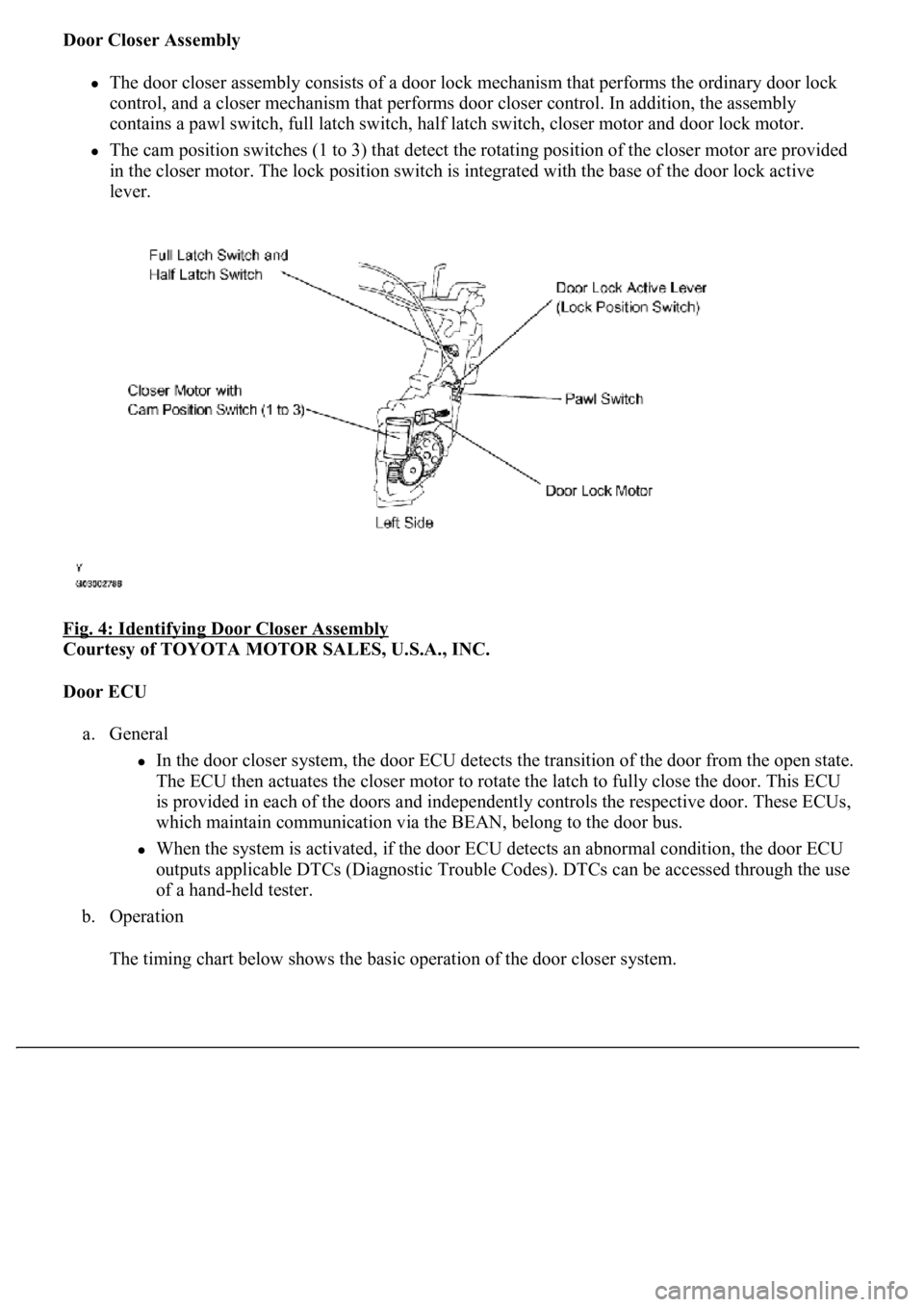
Door Closer Assembly
The door closer assembly consists of a door lock mechanism that performs the ordinary door lock
control, and a closer mechanism that performs door closer control. In addition, the assembly
contains a pawl switch, full latch switch, half latch switch, closer motor and door lock motor.
The cam position switches (1 to 3) that detect the rotating position of the closer motor are provided
<004c005100030057004b004800030046004f0052005600480055000300500052005700520055001100030037004b00480003004f00520046004e0003005300520056004c0057004c0052005100030056005a004c00570046004b0003004c00560003004c00
5100570048004a005500440057004800470003005a004c0057[h the base of the door lock active
lever.
Fig. 4: Identifying Door Closer Assembly
Courtesy of TOYOTA MOTOR SALES, U.S.A., INC.
Door ECU
a. General
In the door closer system, the door ECU detects the transition of the door from the open state.
The ECU then actuates the closer motor to rotate the latch to fully close the door. This ECU
is provided in each of the doors and independently controls the respective door. These ECUs,
which maintain communication via the BEAN, belong to the door bus.
When the system is activated, if the door ECU detects an abnormal condition, the door ECU
outputs applicable DTCs (Diagnostic Trouble Codes). DTCs can be accessed through the use
of a hand-held tester.
b. Operation
The timin
g chart below shows the basic operation of the door closer system.
Page 2185 of 4500
Fig. 7: Identifying Closer Motor And Cam Position Switch
Courtesy of TOYOTA MOTOR SALES, U.S.A., INC.
Page 2186 of 4500
Fig. 8: Identifying Switches ON/OFF Patterns
Courtesy of TOYOTA MOTOR SALES, U.S.A., INC.
When rotation operation is normal, the operation starts from the top of the list. During reverse
rotation, operation starts from the bottom of the list.
CLOSER MOTOR CONDITION
e. Fail-safe
The door ECU stops the door closer system if it detects a malfunction in the system. However, the
doors can be opened or closed manually.
HINT:
Use this procedure to troubleshoot the door closer system.
The hand-held tester should be used in steps 3, 4 and 6.
1.VEHICLE BROUGHT TO WORKSHOP
Go To Next Step.
Closer Motor ConditionCPS1CPS2CPS3
(Error range)OFFOFFOFF
Cam position switch pattern 1OFFONON
Cam position switch pattern 2OFFONOFF
Cam position switch pattern 3ONONOFF
Cam position switch pattern (4)ONOFFON
(Error range)OFFOFFOFF
Page 2190 of 4500
1.DRIVER DOOR ECU
Fig. 11: Identifying Driver Door ECU Terminals
Courtesy of TOYOTA MOTOR SALES, U.S.A., INC.
a. Disconnect the F23 and D25 ECU connectors
b. Measure the voltage and resistance of the wire harness side connectors.
Fig. 12: Driver Door ECU Terminals Reference Chart
Courtesy of TOYOTA MOTOR SALES, U.S.A., INC.
If the result is not as specified, there may be a malfunction on the wire harness side.
c. Reconnect the F23 and D25 ECU connectors.
d. Measure the volta
ge of the connectors.