Page 1191 of 4500
1.STEERING SYSTEM HANDLING PRECAUTIONS
a. Care must be taken when replacing parts. Incorrect replacement could affect the performance of the
steering system and result in hazardous driving.
2.SRS AIRBAG SYSTEM HANDLING PRECAUTIONS
a. The LEXUS LS430 is equipped with an SRS (Supplemental Restraint System) such as the driver's
airbag and front passenger airbag. Failure to carry out service operations in correct sequence could
cause unexpected SRS deployment during servicing and may lead to a serious accident. Before
servicing (including removal or installation of parts, inspection or replacement), be sure to read the
precautionary notice for the supplemental restraint system (see PRECAUTION
).
Fig. 1: [Identifying Bus Line]
Courtesy of TOYOTA MOTOR SALES, U.S.A., INC.
3.BUS LINE REPAIR
a. After repairing the bus line with solder, wrap the repaired part with vinyl tape (see ELECTRONIC
CIRCUIT INSPECTION PROCEDURE ).
Page 1744 of 4500

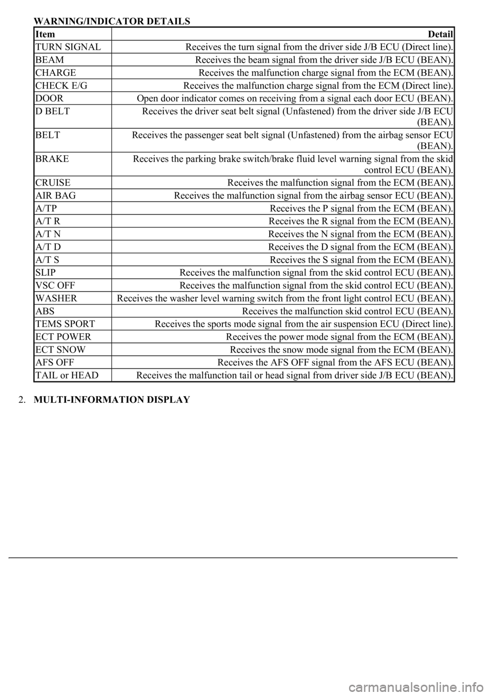
WARNING/INDICATOR DETAILS
2.MULTI-INFORMATION DISPLAY
ItemDetail
TURN SIGNALReceives the turn signal from the driver side J/B ECU (Direct line).
BEAMReceives the beam signal from the driver side J/B ECU (BEAN).
CHARGEReceives the malfunction charge signal from the ECM (BEAN).
CHECK E/GReceives the malfunction charge signal from the ECM (Direct line).
DOOROpen door indicator comes on receiving from a signal each door ECU (BEAN).
D BELTReceives the driver seat belt signal (Unfastened) from the driver side J/B ECU
(BEAN).
BELTReceives the passenger seat belt signal (Unfastened) from the airbag sensor ECU
(BEAN).
BRAKEReceives the parking brake switch/brake fluid level warning signal from the skid
control ECU (BEAN).
CRUISEReceives the malfunction signal from the ECM (BEAN).
AIR BAGReceives the malfunction signal from the airbag sensor ECU (BEAN).
A/TPReceives the P signal from the ECM (BEAN).
A/T RReceives the R signal from the ECM (BEAN).
A/T NReceives the N signal from the ECM (BEAN).
A/T DReceives the D signal from the ECM (BEAN).
A/T SReceives the S signal from the ECM (BEAN).
SLIPReceives the malfunction signal from the skid control ECU (BEAN).
VSC OFFReceives the malfunction signal from the skid control ECU (BEAN).
WASHERReceives the washer level warning switch from the front light control ECU (BEAN).
ABSReceives the malfunction skid control ECU (BEAN).
TEMS SPORTReceives the sports mode signal from the air suspension ECU (Direct line).
ECT POWERReceives the power mode signal from the ECM (BEAN).
ECT SNOWReceives the snow mode signal from the ECM (BEAN).
AFS OFFReceives the AFS OFF signal from the AFS ECU (BEAN).
TAIL or HEADReceives the malfunction tail or head signal from driver side J/B ECU (BEAN).
Page 1776 of 4500

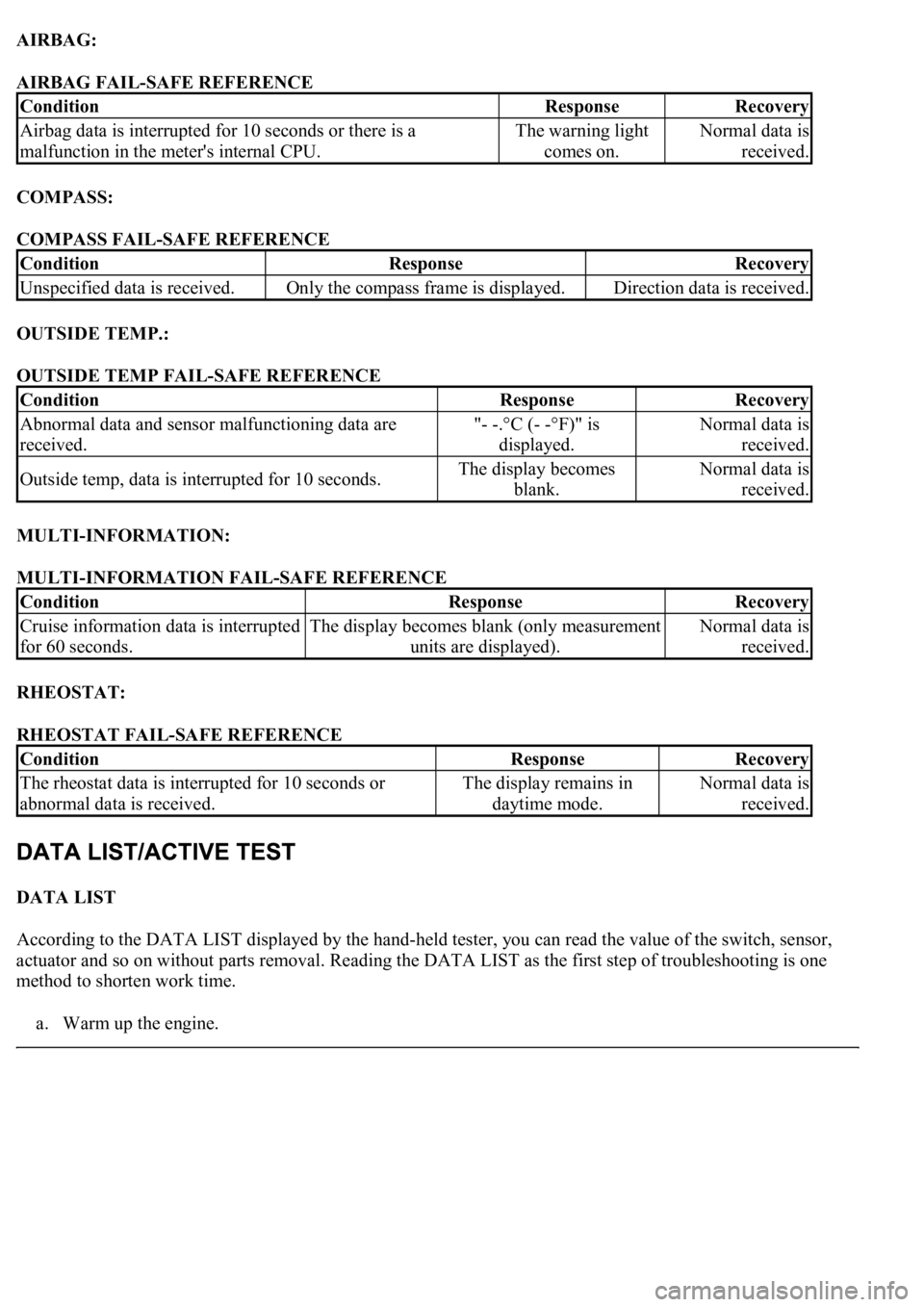
AIRBAG:
AIRBAG FAIL-SAFE REFERENCE
COMPASS:
COMPASS FAIL-SAFE REFERENCE
OUTSIDE TEMP.:
OUTSIDE TEMP FAIL-SAFE REFERENCE
MULTI-INFORMATION:
MULTI-INFORMATION FAIL-SAFE REFERENCE
RHEOSTAT:
RHEOSTAT FAIL-SAFE REFERENCE
DATA LIST
According to the DATA LIST displayed by the hand-held tester, you can read the value of the switch, sensor,
actuator and so on without parts removal. Reading the DATA LIST as the first step of troubleshooting is one
method to shorten work time.
a. Warm up the en
gine.
ConditionResponseRecovery
Airbag data is interrupted for 10 seconds or there is a
malfunction in the meter's internal CPU.The warning light
comes on.Normal data is
received.
ConditionResponseRecovery
Unspecified data is received.Only the compass frame is displayed.Direction data is received.
ConditionResponseRecovery
Abnormal data and sensor malfunctioning data are
received."- -.°C (- -°F)" is
displayed.Normal data is
received.
Outside temp, data is interrupted for 10 seconds.The display becomes
blank.Normal data is
received.
ConditionResponseRecovery
Cruise information data is interrupted
for 60 seconds.The display becomes blank (only measurement
units are displayed).Normal data is
received.
ConditionResponseRecovery
<0037004b004800030055004b004800520056005700440057000300470044005700440003004c00560003004c005100570048005500550058005300570048004700030049005200550003001400130003005600480046005200510047005600030052005500
03[
abnormal data is received.The display remains in
daytime mode.Normal data is
received.
Page 1778 of 4500
Fig. 38: Body No.3 Data List Item Reference Chart
Courtesy of TOYOTA MOTOR SALES, U.S.A., INC.
BODY No.4:
Fig. 39: Body No.4 Data List Item Reference Chart
Courtesy of TOYOTA MOTOR SALES, U.S.A., INC.
BODY No.5:
Fig. 40: Body No.5 Data List Item Reference Chart
Courtesy of TOYOTA MOTOR SALES, U.S.A., INC.
SRS AIRBAG:
Page 1779 of 4500

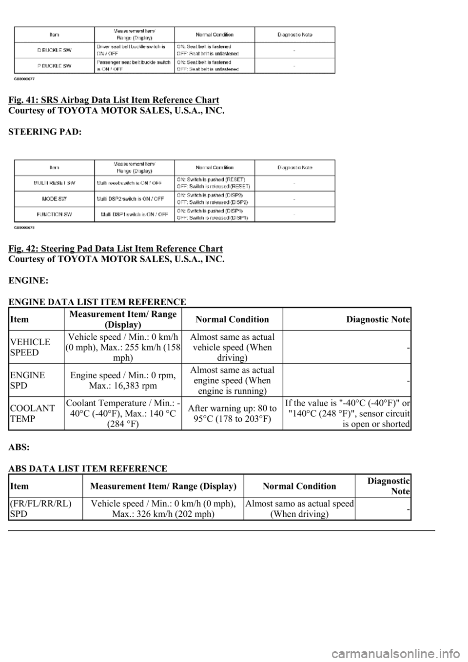
Fig. 41: SRS Airbag Data List Item Reference Chart
Courtesy of TOYOTA MOTOR SALES, U.S.A., INC.
STEERING PAD:
Fig. 42: Steering Pad Data List Item Reference Chart
Courtesy of TOYOTA MOTOR SALES, U.S.A., INC.
ENGINE:
ENGINE DATA LIST ITEM REFERENCE
ABS:
ABS DATA LIST ITEM REFERENCE
ItemMeasurement Item/ Range
(Display)Normal ConditionDiagnostic Note
VEHICLE
SPEEDVehicle speed / Min.: 0 km/h
(0 mph), Max.: 255 km/h (158
mph)Almost same as actual
vehicle speed (When
driving)
-
ENGINE
SPDEngine speed / Min.: 0 rpm,
Max.: 16,383 rpmAlmost same as actual
engine speed (When
engine is running)
-
COOLANT
TEMPCoolant Temperature / Min.: -
40°C (-40°F), Max.: 140 °C
(284 °F)After warning up: 80 to
95°C (178 to 203°F)If the value is "-40°C (-40°F)" or
"140°C (248 °F)", sensor circuit
is open or shorted
ItemMeasurement Item/ Range (Display)Normal ConditionDiagnostic
Note
(FR/FL/RR/RL)
SPDVehicle speed / Min.: 0 km/h (0 mph),
Max.: 326 km/h (202 mph)Almost samo as actual speed
(When driving)-
Page 1781 of 4500

ECT PWR INDICIndicat. Lamp ECT PWR (OFF/ON)Confirm that the vehicle is stopped
and engine idling
Rr FOG INDICIndicat. Lamp Rr FOG (OFF/ON)Confirm that the vehicle is stopped
and engine idling
OIL LEVEL WARNIndicat. Lamp OIL LEVEL (OFF/ON)Confirm that the vehicle is stopped
and engine idling
Rr LIGHT INDICIndicat. Lamp Rr Light (OFF/ON)Confirm that the vehicle is stopped
and engine idling
VSC WARNIndicat. Lamp VSC (OFF/ON)Confirm that the vehicle is stopped
and engine idling
ARS WARNIndicat. Lamp ARS (OFF/ON)Confirm that the vehicle is stopped
and engine idling
MIL (ENGINE)Indicat. Lamp ENGINE (OFF/ON)Confirm that the vehicle is stopped
and engine idling
LOW WASHER
WARNIndicat. Lamp WASHER (OFF/ON)Confirm that the vehicle is stopped
and engine idling
ItemTest DetailsDiagnostic Note
SRS WARNIndicat. Lamp AIRBAG (OFF/ON)Confirm that the vehicle is stopped
and engine idling
HIGH BEAM INDICIndicat. Lamp BEAM (OFF/ON)Confirm that the vehicle is stopped
and engine idling
TURN INDIC-LIndicat. Lamp TURN L (OFF/ON)Confirm that the vehicle is stopped
and engine idling
TURN INDIC-RIndicat. Lamp TURN R (OFF/ON)Confirm that the vehicle is stopped
and engine idling
ABS WARNIndicat. Lamp ABS (OFF/ON)Confirm that the vehicle is stopped
and engine idling
TRC OFF INDICIndicat. Lamp TRAC (TRC) OFF
(OFF/ON)Confirm that the vehicle is stopped
and engine idling
SLIP INDICIndicat. Lamp SLIP (OFF/ON)Confirm that the vehicle is stopped
and engine idling
O/D OFF INDICIndicat. Lamp O/D OFF (OFF/ON)Confirm that the vehicle is stopped
and engine idling
ODO/TRIP DISPIndicat. ODO/TRIP DISPLAY (OFF/ON)Confirm that the vehicle is stopped
and engine idling
A/T OIL TEMPA/T OIL temperature operation (OFF/ON)Confirm that the vehicle is stopped
and engine idling
L-CRUISE DISPIndicat. Laser Cruise DISPLAY (OFF/ON)Confirm that the vehicle is stopped
and engine idling
L-CRS CHECK INDIndicat. Lamp L-CRUISE CHECK
(OFF/ON)Confirm that the vehicle is stopped
and engine idling
L-CRS READY INDIndicat. Lamp L-CRUISE READY
(OFF/ON)Confirm that the vehicle is stopped
and engine idling
Fr FOG INDICIndicat. Lamp Fr FOG (OFF/ON)Confirm that the vehicle is stopped
Page 1812 of 4500
Fig. 65: Driver'S Seat Belt Warning Lamp Wiring Diagram
Courtesy of TOYOTA MOTOR SALES, U.S.A., INC.
INSPECTION PROCEDURE
HINT:
If there is an open in the ground circuit (Airbag sensor assy center), the airbag sensor assy center outputs DTCs.
Perform troubleshooting with the "Supplemental Restraint System" 05-1026.
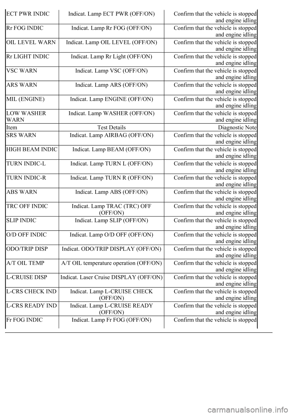
1.PERFORM ACTIVE TEST BY HAND-HELD TESTER
a. Operate the hand-held tester according to the steps on the display and select the "ACTIVE TEST".
METER:
ACTIVE TEST REFERENCE
OK:
Switch condition (ON/OFF) can be switched by ACTIVE TEST.
NG: REPLACE COMBINATION METER ASSY (SEE OVERHAUL
)
OK: GO TO NEXT STEP
ItemTest DetailsDiagnostic Note
D-BELT
REMINDIndicat. Lamp D-SEAT BELT
(OFF/ON)Confirm that the vehicle is stopped and engine
idling
Page 1813 of 4500
2.READ VALUE OF HAND-HELD TESTER (DRIVER SEAT BELT)
a. Operate the hand-held tester according to the steps on the display and select the "DATA LIST".
SRS AIRBAG:
Fig. 66: SRS Airbag Data List Reference Chart
Courtesy of TOYOTA MOTOR SALES, U.S.A., INC.
OK:
Indicator lamp (ON/OFF) can be switched by actual operation.
NG: Go to step 3
OK: REPLACE COMBINATION METER ASSY (SEE OVERHAUL
)
3.INSPECT FRONT SEAT INNER BELT ASSY (DRIVER SIDE)
a. Disconnect the connector from the front seat inner belt assy (Driver Side).
b. Measure the resistance according to the value (s) in the table below.
Standard
RESISTANCE SPECIFICATIONS
NG: REPLACE FRONT SEAT INNER BELT ASSY (DRIVER SIDE)
Terminal NoConditionSpecified condition
B4-2 - B4-5Seat belt is fastenedApprox. 330 ohms
B4-2 - B4-5Seat belt is unfastenedApprox. 1,330 ohms