2003 LEXUS LS430 air filter
[x] Cancel search: air filterPage 210 of 4500

Fig. 6: Air Conditioning System Diagram (2 Of 2)
Courtesy of TOYOTA MOTOR SALES, U.S.A., INC.
1.GENERAL
a. The air conditioning system has the following features:
In compliance with the temperature set at the temperature control switch, the neural network
control calculates the outlet temperature based on the input signals from various sensors. In
addition, corrections in accordance with the signals from the evaporative temperature sensor
and the water temperature sensor are added to control the outlet air temperature.
Controls the front and rear blower motors in accordance with the airflow volume that has
been calculated by the neural network control based on the input signals from various
sensors.
Automatically switches the outlets in accordance with the outlet mode ratio that has been
calculated by the neural network control based on the input signals from various sensors.
Automatically controls the air inlet control damper in accordance with the airflow volume
that has been calculated by the neural network control.
Turns the compressor on/off and controls the discharge capacity based on the signals from
various sensors.
Based on the signals from the ambient temperature sensor, this control calculates the outside
temperature, which is then corrected in the air conditioner ECU, and shown in the multi-
information display in the combination meter.
Switched the rear defogger and outside rear view mirror heaters on for 15 minutes when the
rear defogger switch is switched on. Switched them off if the switch is pressed while they are
operating.
Controls the orientation and the angle of the front center register based on the input signals
from various sensors and on the outlet mode.
Determines whether the clean air filter (for the front A/C) is clogged by monitoring the air
inlets, and airflow volume.
The A/C amplifier automatically controls the air inlets based on the signals from the smog
ventilation sensor.
Improves the air quality by linking the air inlet control damper and the blower motor (for the
rear A/C and air purifier), based on the signals from the exhaust gas sensor and the smoke
sensor.
Checks the sensors in accordance with operation of the air conditioner switches.
2.MODEL POSITION AND DAMPER OPERATION
Page 228 of 4500

AIR MIX STEP-
DAir mix servomotor target STEP
(Driver side) / min.: 257 STEP
max.: 1571 STEPMAX COOL: Approx. 257 STEP
MAX HOT: Approx. 1,571 STEP-
AIR MIX STEP-
PAir mix servomotor target STEP
(Passenger side) / min.: 257 STEP
max.: 1571 STEPMAX COOL: Approx. 257 STEP
MAX HOT: Approx. 1,571 STEP-
AIR OUT STEP-
DAir outlet servomotor target STEP
(Driver side) / min.: 274 STEP
max.: 2060 STEPFACE: Approx. 274 STEP DEF:
Approx. 2,060 STEP-
AIR OUT STEP-
PAir outlet servomotor target STEP
(Passenger side) / min.: 274 STEP
max.: 2060 STEPFACE: Approx. 274 STEP DEF:
Approx. 2,060 STEP-
HAND FREE
TELHand free telephone / OFF, ON--
BLOWER
LEVELBlower motor speed level / min.:
0 level max.: 31 levelIncreases in the range between 0 and
31 as the speed increase-
AMBI TEMP
Adjusted ambient temperature /
min.: -30.8°C (-23.44°F) max.:
50.8°C (123.44°F)
--
LOW VOLT
COUNT+B abnormal low voltage / min.: 0
times max.: 255 times--
EMISS GAS
SENSEmission gas / min.: 0 V max.:
255 VIncreases as the gas amount increases-
SET TEMP
SHIFTShift set temperature / +2C, +1C,
NORMAL, -1C, -2CCustomized value will be displayed-
AIR INLET
MODEAir inlet mode / AUTO,
MANUALCustomized value will be displayed-
COMPRESSOR
MODECompressor mode / AUTO,
MANUALCustomized value will be displayed-
COMPRS/DEF
OPERCompressor/ DEF operation
mode /LINK, NORMALCustomized value will be displayed-
MOTOR
INITIALIZEMotor initialize after IG SW being
turned OFFCustomized value will be displayed-
EVAP CTRLEvaporator control /AUTO,
MANUALCustomized value will be displayed-
GAS SENS
SHIFT
Emission Gas Sensor Shift / MU
MORE, MORE, LI MORE,
NORMAL, LI LESS, LESS, MU
LESS
Customized value will be displayed-
AUTO MODESwing resister auto mode /
AUTO, MANUALCustomized value will be displayed-
BUTTON PRS
BUZButton press buzzer / ON, OFFCustomized value will be displayed-
FILTER SENSFilter sensor / LESS, NORMAL,
MORECustomized value will be displayed-
Page 229 of 4500

DATA LIST / ENGINE AND ECT / ALL:
DATA LIST / ENGINE AND ECT / ALL
2.ACTIVE TEST
HINT:
Performing the ACTIVE TEST
using the hand-held tester allows the relays, VSV, actuators and so on to
operate without parts removal. Performing the ACTIVE TEST
as the first STEP of troubleshooting is
one way to shorten labor time.
It is possible to display the DATA LIST on the hand-held tester during the ACTIVE TEST.
a. Connect the hand-held tester to the DLC3.
b. Turn the ignition switch to the ON position.
c. From the display on tester, perform the "ACTIVE TEST
".
ACTIVE TEST / AIR CONDITIONER:
ACTIVE TEST / AIR CONDITIONER
FOOT AIR
LEAKFoot air leak / ON, OFFCustomized value will be displayed-
DESTINATION
Destination / DOMEST, USA,
EUROPE, AUSTRAL,
MIDEAST, NO INFO
Changes with destinations-
REAR SOLAR
SENSRear solar sensor / min.: 0 max.:
255Changes depending on brightness-
NOX GAS SENSEmission gas Nox sensor / min.: 0
max.: 255Increases as the gas amount increases-
ItemMeasurement Item / Display
(Range)Normal ConditionDiagnostic
Note
REG PRESS
SENSRegulator pressure sensor / min.:
0 max.: 255Actual regulator pressure is displayed-
FILTER FLOW
VOLFilter flow volume / min.: 0 max.:
65535Actual filter flow volume is displayed-
REG CTRL
CURRNTRegulator control current / min.: 0
A max.: 255 A--
HUMIDITY
SENSHumidity sensor / min.: 0% max.:
100%Actual room humidity is displayed-
#CODESNumber of Trouble Codes / min.:
0 max.: 255Number of DTCs will be displayed-
ItemMeasurement Item/Display (Range)Normal ConditionDiagnostic Note
A/C SIGA/C signal/ ON or OFFA/C ON: ON-
Page 241 of 4500

1.STEP MOTORS INITIALIZING FUNCTION
STEP motor initializing procedure (Automatic initializing)
1. When the battery is reconnected and the ignition switch is turned to the ON position for the first
time, the initializing function of the STEP motors is activated. In this case, the "FRONT DEF"
indicator blinks.
SET TEMP SHIFT
(Set Temperature
Shift)
NORMALTo control with the shifted temperature
against the display temperature.+2C/+1C/ NORMAL -
1C / -2C
AIR INLET MODE
(Air Inlet Mode)AUTO
In case of turning the A/C ON when you
desire to make the compartment cool down
quickly, this is the function to change the
mode automatically to RECIRCULATED
mode.
MANUAL / AUTO
COMPRESSOR
MODE (Compressor
Mode)
AUTO
Function to turn the A/C ON automatically
by pressing the AUTO button when the
blower is ON and the A/C is OFF.
MANUAL / AUTO
COMPRS/DEF OPER
(Compressor/Air Inlet
DEF Operation)
LINK
Function to turn the A/C ON automatically
linking with the FRONT DEF button when
A/C is OFF.
NORMAL / LINK
MOTOR INITIALIZ
(STEP Motor
Initializing (IG/off))
OFFFunction to initialize the STEP motor after
the ignition switch is OFF.ON / OFF
EVAP CTRL
(External Variable
Control OFF)
AUTO
Function to set the evaporator control to the
AUTOMATIC position (AUTO) to save
power or to the coldest position
(MANUAL) to dehumidify the air and to
prevent the windows from fogging up.
MANUAL / AUTO
GAS SENS SHIFT
(Shift Emission Gas
Sensor Sensitivity)
NORMALFunction to change the sensitivity of the
exhaust gas sensor.
MU MORE /MORE / LI
MORE / NORMAL / LI
LESS / LESS / MU
LESS
AUTO MODE
(Cancel Auto Mode)AUTOFunction to swing the vent vans
automatically when A/C is ON.MANUAL / AUTO
BUTTON PRS BUS
(Cancel Operating
Switch Sound)
ONFunction to sound a buzzer when a button
is pressed.OFF / ON
FILTER SENS (Shift
Filter Clog Sensitivity)NORMALFunction to change the sensitivity of the air
conditioning filter choking sensor.LESS / NORMAL /
MORE
FOOT AIR LEAK
(Cancel Air Outlet
Foot II)
ONFunction to cut off the airstream felt
underfoot while the vehicle is moving.OFF / ON
Page 1668 of 4500

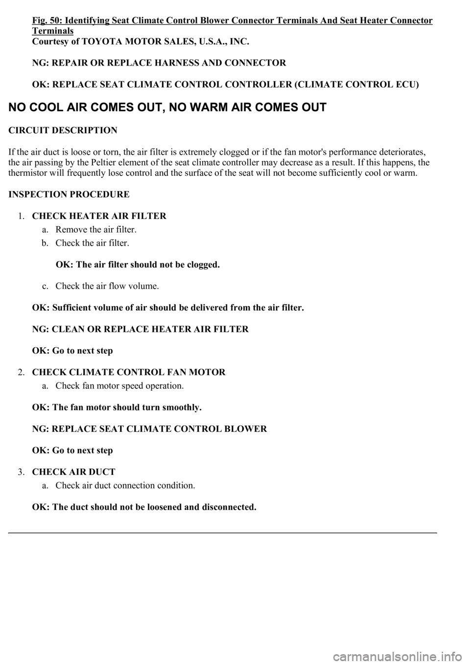
Fig. 50: Identifying Seat Climate Control Blower Connector Terminals And Seat Heater Connector
Terminals
Courtesy of TOYOTA MOTOR SALES, U.S.A., INC.
NG: REPAIR OR REPLACE HARNESS AND CONNECTOR
OK: REPLACE SEAT CLIMATE CONTROL CONTROLLER (CLIMATE CONTROL ECU)
CIRCUIT DESCRIPTION
If the air duct is loose or torn, the air filter is extremely clogged or if the fan motor's performance deteriorates,
the air passing by the Peltier element of the seat climate controller may decrease as a result. If this happens, the
thermistor will frequently lose control and the surface of the seat will not become sufficiently cool or warm.
INSPECTION PROCEDURE
1.CHECK HEATER AIR FILTER
a. Remove the air filter.
b. Check the air filter.
OK: The air filter should not be clogged.
c. Check the air flow volume.
OK: Sufficient volume of air should be delivered from the air filter.
NG: CLEAN OR REPLACE HEATER AIR FILTER
OK: Go to next step
2.CHECK CLIMATE CONTROL FAN MOTOR
a. Check fan motor speed operation.
OK: The fan motor should turn smoothly.
NG: REPLACE SEAT CLIMATE CONTROL BLOWER
OK: Go to next step
3.CHECK AIR DUCT
a. Check air duct connection condition.
OK: The duct should not be loosened and disconnected.
Page 2637 of 4500

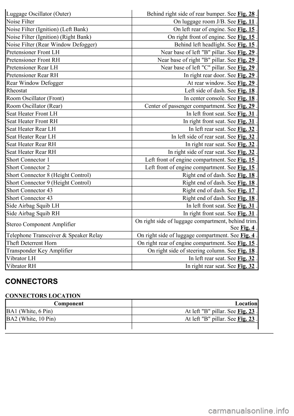
CONNECTORS LOCATION
Luggage Oscillator (Outer)Behind right side of rear bumper. See Fig. 28 .
Noise FilterOn luggage room J/B. See Fig. 11 .
Noise Filter (Ignition) (Left Bank)On left rear of engine. See Fig. 15 .
Noise Filter (Ignition) (Right Bank)On right front of engine. See Fig. 15 .
Noise Filter (Rear Window Defogger)Behind left headlight. See Fig. 15 .
Pretensioner Front LHNear base of left "B" pillar. See Fig. 29 .
Pretensioner Front RHNear base of right "B" pillar. See Fig. 29 .
Pretensioner Rear LHNear base of left "C" pillar. See Fig. 29 .
Pretensioner Rear RHIn right rear door. See Fig. 29 .
Rear Window DefoggerAt rear window. See Fig. 29 .
RheostatLeft side of dash. See Fig. 18 .
Room Oscillator (Front)In center console. See Fig. 18 .
Room Oscillator (Rear)Center of passenger compartment. See Fig. 29 .
Seat Heater Front LHIn left front seat. See Fig. 31 .
Seat Heater Front RHIn right front seat. See Fig. 31 .
Seat Heater Rear LHIn left rear seat. See Fig. 32 .
Seat Heater Rear LHIn left side of rear seat. See Fig. 32 .
Seat Heater Rear RHIn right rear seat. See Fig. 32 .
Seat Heater Rear RHIn right side of rear seat. See Fig. 32 .
Short Connector 1Left front of engine compartment. See Fig. 15 .
Short Connector 2Left front of engine compartment. See Fig. 15 .
Short Connector 8 (Height Control)Right end of dash. See Fig. 18 .
Short Connector 9 (Height Control)Right end of dash. See Fig. 18 .
Short Connector 43Right end of dash. See Fig. 17 .
Short Connector 43Right end of dash. See Fig. 18 .
Side Airbag Squib LHIn left front seat. See Fig. 31 .
Side Airbag Squib RHIn right front seat. See Fig. 31 .
Stereo Component AmplifierOn right side of luggage compartment, behind trim.
See Fig. 4
.
Telephone Transceiver & Speaker RelayOn right side of luggage compartment. See Fig. 4 .
Theft Deterrent HornOn right rear of engine compartment. See Fig. 15 .
Transponder Key AmplifierOn right side of steering column. See Fig. 18 .
Vibrator LHIn left rear seat. See Fig. 32 .
Vibrator RHIn right rear seat. See Fig. 32 .
ComponentLocation
BA1 (White, 6 Pin)At left "B" pillar. See Fig. 23 .
BA2 (White, 10 Pin)At left "B" pillar. See Fig. 23 .
Page 3279 of 4500

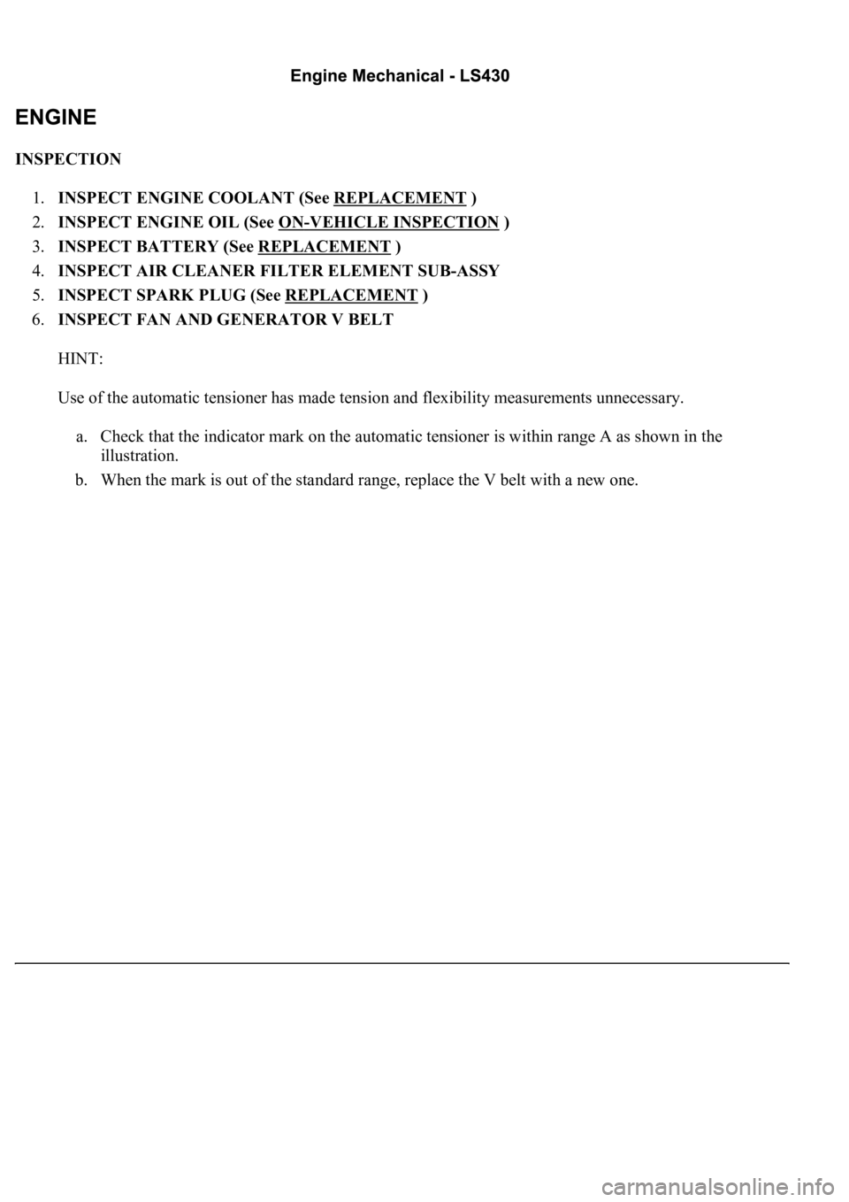
INSPECTION
1.INSPECT ENGINE COOLANT (See REPLACEMENT
)
2.INSPECT ENGINE OIL (See ON
-VEHICLE INSPECTION )
3.INSPECT BATTERY (See REPLACEMENT
)
4.INSPECT AIR CLEANER FILTER ELEMENT SUB-ASSY
5.INSPECT SPARK PLUG (See REPLACEMENT
)
6.INSPECT FAN AND GENERATOR V BELT
HINT:
Use of the automatic tensioner has made tension and flexibility measurements unnecessary.
a. Check that the indicator mark on the automatic tensioner is within range A as shown in the
illustration.
b. When the mark is out of the standard range, replace the V belt with a new one.
Page 4259 of 4500

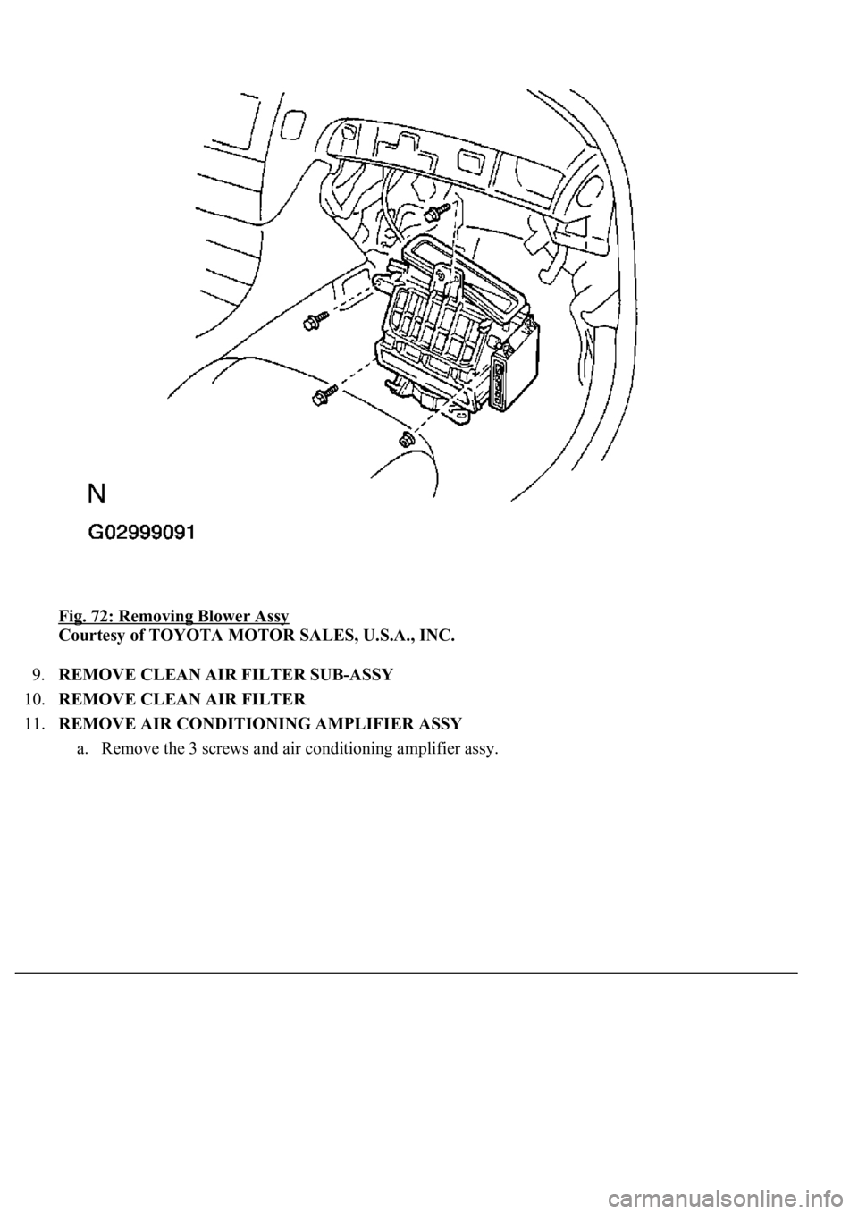
Fig. 72: Removing Blower Assy
Courtesy of TOYOTA MOTOR SALES, U.S.A., INC.
9.REMOVE CLEAN AIR FILTER SUB-ASSY
10.REMOVE CLEAN AIR FILTER
11.REMOVE AIR CONDITIONING AMPLIFIER ASSY
a. Remove the 3 screws and air conditionin
g amplifier assy.