Page 469 of 4500

If the vehicle is raised with its engine running, connect terminals OPB and CG of the DLC3 to stop
the vehicle height control operation of the suspension control ECU.
Do not operate the steering wheel if there is no air in the pneumatic cylinder.
HINT:
The pneumatic cylinder could be damaged if twisted without air in the cylinder.
In the case of lifting down the vehicle without air in the cylinder, make sure all the pipes are securely
connected.
HINT:
The pneumatic cylinder could be damaged if any pipe is disconnected while lifting down the vehicle.
Do not apply battery voltage to the compressor motor for more than 60 seconds to prevent damage to the
motor.
HINT:
When it is necessary to perform the operation by charging the battery for more than 60 seconds, for example
height recovery without air in the cylinder, proceed to the operation as follows: after 60 seconds have passed,
turn the ignition switch off once, and then turn the ignition switch to the ON position again for commencement
of operation.
Page 470 of 4500
Fig. 2: Identifying Air Suspension System Components Location
Courtesy of TOYOTA MOTOR SALES, U.S.A., INC.
Page 471 of 4500
Fig. 3: Air Suspension System Diagram
Courtesy of TOYOTA MOTOR SALES, U.S.A., INC.
1.AIR SUSPENSION SYSTEM DESCRIPTION
Page 475 of 4500
Fig. 5: Air Suspension System Check Sheet
Courtesy of TOYOTA MOTOR SALES, U.S.A., INC.
1.TEST MODE
Page 478 of 4500
7. Read the test mode DTCs by following the prompts on the tester screen.
HINT:
Refer to the hand-held tester operator's manual for further details.
DTC of Air Suspension System test mode function:
If a malfunction code is displayed during the test mode DTC check, check the circuit listed
for that code. For details of each code, refer to "See Procedure" under the respective "DTC
No." in the chart.
Fig. 7: DTC Of Air Suspension System Test Mode Function
Courtesy of TOYOTA MOTOR SALES, U.S.A., INC.
8. After completing the test mode, disconnect the tester and turn the ignition switch off.
If a normal system code is displayed during the DTC check but the problem still occurs, check the circuits for
each problem s
ymptom in the order given in the table below and proceed to the relevant troubleshooting page.
Page 480 of 4500

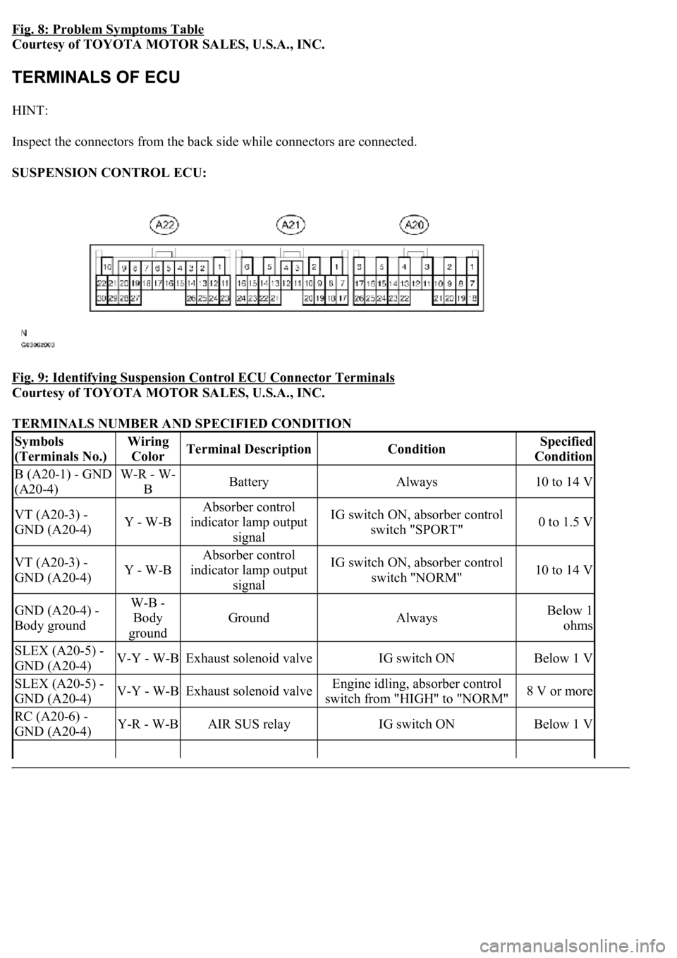
Fig. 8: Problem Symptoms Table
Courtesy of TOYOTA MOTOR SALES, U.S.A., INC.
HINT:
Inspect the connectors from the back side while connectors are connected.
SUSPENSION CONTROL ECU:
Fig. 9: Identifying Suspension Control ECU Connector Terminals
Courtesy of TOYOTA MOTOR SALES, U.S.A., INC.
TERMINALS NUMBER AND SPECIFIED CONDITION
Symbols
(Terminals No.)Wiring
ColorTerminal DescriptionConditionSpecified
Condition
B (A20-1) - GND
(A20-4)W-R - W-
BBatteryAlways10 to 14 V
VT (A20-3) -
GND (A20-4)Y - W-B
Absorber control
indicator lamp output
signalIG switch ON, absorber control
switch "SPORT"0 to 1.5 V
VT (A20-3) -
GND (A20-4)Y - W-B
Absorber control
indicator lamp output
signalIG switch ON, absorber control
switch "NORM"10 to 14 V
GND (A20-4) -
Body groundW-B -
Body
ground
GroundAlwaysBelow 1
ohms
SLEX (A20-5) -
GND (A20-4)V-Y - W-BExhaust solenoid valveIG switch ONBelow 1 V
SLEX (A20-5) -
GND (A20-4)V-Y - W-BExhaust solenoid valveEngine idling, absorber control
switch from "HIGH" to "NORM"8 V or more
RC (A20-6) -
GND (A20-4)Y-R - W-BAIR SUS relayIG switch ONBelow 1 V
Page 481 of 4500

RC (A20-6) -
GND (A20-4)Y-R - W-BAIR SUS relay
Engine idling, height control switch
from "NORM" to "HIGH" during
compressor operation
8 V or more
CANH (A20-7) -
CANL (A20-8)BR - YCAN communication
lineIG switch OFF54 to 67
ohms
SW1 (A20-9) -
GND (A20-4)O - W-BAbsorber control switch
input signalEngine idling, absorber control
switch "NORM" position10 to 14 V
SW1 (A20-9) -
GND (A20-4)O - W-BAbsorber control switch
input signalEngine idling, absorber control
switch "SPORT" position0 to 1.5 V
SIL (A20-13) -
GND (A20-4)W-G - W-
BDiagnosis tester
communication lineIG switch ONPulse
generation
TD (A20-14) -
GND (A20-4)L-B - W-BHeight control is not
operatingIG switch ON10 to 14 V
HSW (A20-15) -
GND (A20-4)LG-B - W-
BHeight control switch
input signalIG switch ON, height control
switch "NORM" position10 to 14 V
HSW (A20-15) -
GND (A20-4)LG-B - W-
BHeight control switch
input signalIG switch ON, height control
switch "HIGH" position0 to 1.5 V
SLFR (A20-16) -
GND (A20-4)G-W - W-
BHeight control solenoid
valve (FR)IG switch ONBelow 1 V
SLFR (A20-16) -
GND (A20-4)G-W - W-
BHeight control solenoid
valve (FR)Engine idling, height control switch
from "NORM" to "HIGH" or
reverse
8 V or more
SLFL (A20-17) -
GND (A20-4)R-W - W-
BHeight control solenoid
valve (FL)IG switch ONBelow 1 V
SLFL (A20-17) -
GND (A20-4)R-W - W-
BHeight control solenoid
valve (FL)Engine idling, height control switch
from "NORM" to "HIGH" or
reverse
8 V or more
SBL1 (A20-18) -
GND (A20-4)LG-R - W-
BHeight control sensor
power source (FL)IG switch ON4.5 to 5.5 V
VH (A20-19) -
GND (A20-4)P - W-BHeight control indicator
output signalIG switch ON, height control
switch "HIGH"0 to 1.5 V
SBR1 (A20-20) -
GND (A20-4)V-R - W-BHeight control indicator
output signalIG switch ON, height control
switch "NORM"10 to 14 V
SBR1 (A20-20) -
GND (A20-4)V-R - W-BHeight control sensor
power source (FR)IG switch ON4.5 to 5.5 V
SGR1 (A20-21) -
GND (A20-4)R-L - W-BHeight control sensor
ground (FR)AlwaysBelow 1
ohms
SGL1 (A20-22) -
GND (A20-4)LG-B - W-
BHeight control sensor
ground (FL)AlwaysBelow 1
ohms
FAR+ (A21-1) -
FAR- (A21-2)O - R-YSuspension control
actuator (FR)IG switch ONBelow 1
ohms
FBR+ (A21-3) -
FBR- (A21-4)R-G - L-GSuspension control
actuator (FR)IG switch ONBelow 1
ohms
FAL+ (A21-5) -
FAL- (A21-14)G-B - G-RSuspension control
actuator (FL)IG switch ONBelow 1
ohms
Page 485 of 4500
HINT:
If the hand-held tester display shows UNABLE TO CONNECT TO VEHICLE when the cable of
the hand-held tester is connected to the DLC3, the ignition switch is turned to the ON position and
the tester is operated, there is a problem either on the vehicle side or tester side.
If communication is normal when the tester is connected to another vehicle, inspect the
DLC3 on the original vehicle.
If communication is still not possible when the tester is connected to another vehicle, the
problem is probably in the tester itself, so consult the Service Department listed in the tester's
instruction manual.
c. Indicator lamp
1. During the vehicle height control operation, the absorber control indicator lamp blinks when
there is any malfunction in the air suspension system.
CANL (14) - CG (4)LOW-level CAN bus
lineIG switch OFF3 Kohms or higher