Page 1756 of 4500

Once calibration is completed, it is not necessary to perform the above procedures unless the magnetic
field strength is drastically changed.
HINT:
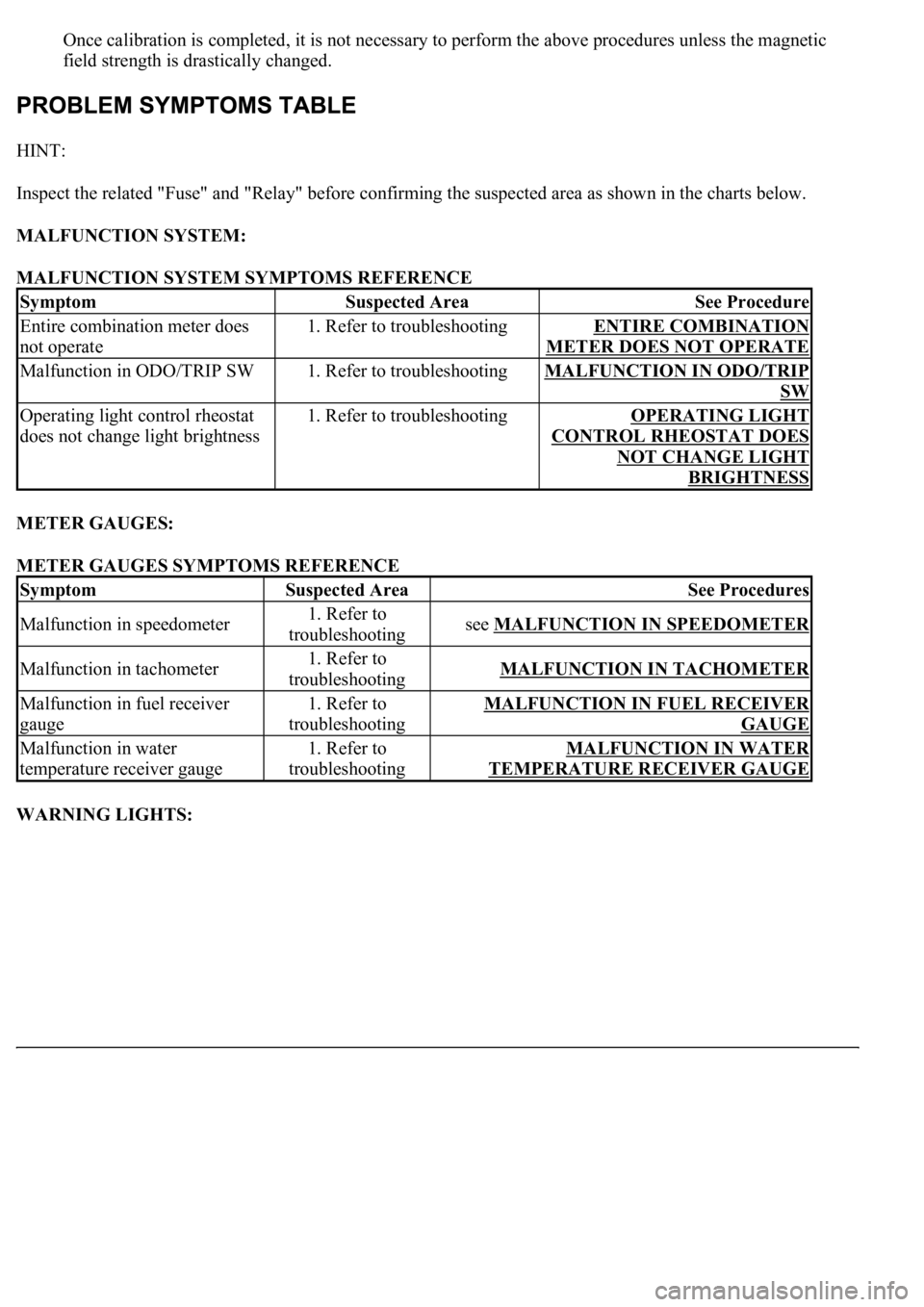
Inspect the related "Fuse" and "Relay" before confirming the suspected area as shown in the charts below.
MALFUNCTION SYSTEM:
MALFUNCTION SYSTEM SYMPTOMS REFERENCE
METER GAUGES:
METER GAUGES SYMPTOMS REFERENCE
WARNING LIGHTS:
SymptomSuspected AreaSee Procedure
Entire combination meter does
not operate1. Refer to troubleshootingENTIRE COMBINATION
METER DOES NOT OPERATE
Malfunction in ODO/TRIP SW1. Refer to troubleshootingMALFUNCTION IN ODO/TRIP
SW
Operating light control rheostat
does not change light brightness1. Refer to troubleshootingOPERATING LIGHT
CONTROL RHEOSTAT DOES
NOT CHANGE LIGHT
BRIGHTNESS
SymptomSuspected AreaSee Procedures
Malfunction in speedometer1. Refer to
troubleshootingsee MALFUNCTION IN SPEEDOMETER
Malfunction in tachometer1. Refer to
troubleshootingMALFUNCTION IN TACHOMETER
Malfunction in fuel receiver
gauge1. Refer to
troubleshootingMALFUNCTION IN FUEL RECEIVER
GAUGE
Malfunction in water
temperature receiver gauge1. Refer to
troubleshootingMALFUNCTION IN WATER
TEMPERATURE RECEIVER GAUGE
Page 1913 of 4500
Fig. 9: Checking RES (RESUME) Function
Courtesy of TOYOTA MOTOR SALES, U.S.A., INC.
If a normal system code is displayed during the DTC check but the problem still occurs, check the circuits for
each problem symptom in the order given in the table below and proceed to the relevant troubleshooting page.
HINT:
Inspect the "Fuse" and "Relay" before confirming the suspected areas as shown in the chart below.
Inspect each malfunction circuit in numerical order for the correspondin
g symptom.
Page 1923 of 4500
Fig. 18: DTC P0500 And P0503 Problem Symptom Diagnostic Chart
Courtesy of TOYOTA MOTOR SALES, U.S.A., INC.
WIRING DIAGRAM
See WIRING DIAGRAM
INSPECTION PROCEDURE
See INSPECTION PROCEDURE
.
CIRCUIT DESCRIPTION
When the brake pedal is depressed, the stop lamp switch assy sends a signal to the ECM. When the ECM
receives this signal, it cancels the cruise control.
Fail-safe function operates to enable normal driving even if there is a malfunction in the stop lamp signal
circuit.
The cancel condition occurs when positive battery voltage is applied to terminal STP.
When the brake is applied, battery positive voltage is normally applied to terminal STP of the ECM through the
STOP fuse and the stop lamp switch assy, and the ECM turns the cruise control off.
Fig. 19: DTC P0571 Problem Symptom Diagnostic Chart
Courtesy of TOYOTA MOTOR SALES, U.S.A., INC.
WIRING DIAGRAM
Page 2450 of 4500
Fig. 18: Multi-Information Display Chart On Combination Meter
Courtesy of TOYOTA MOTOR SALES, U.S.A., INC.
HINT:
The indication is immediately set to "LONG" each time the engine is started.
If a normal system code is displayed during the DTC check but the problem still occurs, check the suspected
areas for each problem symptom in the order given in the table below and proceed to the relevant
troubleshooting page.
HINT:
Inspect the "Fuse" and "Relay" before confirming the suspected areas as shown in the chart below. Inspect each
suspected area for the correspondin
g symptom in numerical order.
Page 2472 of 4500
CIRCUIT DESCRIPTION
See CIRCUIT DESCRIPTION
.
Fig. 42: DTC P0500 And P0503 Problem Symptom Diagnostic Chart
Courtesy of TOYOTA MOTOR SALES, U.S.A., INC.
WIRING DIAGRAM
See WIRING DIAGRAM
.
INSPECTION PROCEDURE
See INSPECTION PROCEDURE
.
CIRCUIT DESCRIPTION
When the brake pedal is depressed, the stop lamp switch assy sends a signal to the ECM. When the ECM
receives this signal, it cancels the cruise control.
The fail-safe function operates to enable normal driving even if there is a malfunction in the stop lamp signal
circuit.
The cancel condition occurs when positive battery voltage is applied to terminal STP.
When the brake is applied, battery positive voltage is normally applied to terminal STP of the ECM through the
STOP fuse and the stop lamp switch ass
y, and the ECM turns the cruise control off.
Page 2550 of 4500
Fig. 18: Multi-Information Display Chart On Combination Meter
Courtesy of TOYOTA MOTOR SALES, U.S.A., INC.
HINT:
The indication is immediately set to "LONG" each time the engine is started.
If a normal system code is displayed during the DTC check but the problem still occurs, check the suspected
areas for each problem symptom in the order given in the table below and proceed to the relevant
troubleshooting page.
HINT:
Inspect the "Fuse" and "Relay" before confirming the suspected areas as shown in the Fig. 19
below. Inspect
each suspected area for the correspondin
g symptom in numerical order.
Page 2573 of 4500
CIRCUIT DESCRIPTION
SEE CIRCUIT DESCRIPTION
.
Fig. 44: DTC P0500 And P0503 Problem Symptom Diagnostic Chart
Courtesy of TOYOTA MOTOR SALES, U.S.A., INC.
WIRING DIAGRAM
SEE WIRING DIAGRAM
.
INSPECTION PROCEDURE
SEE INSPECTION PROCEDURE
.
CIRCUIT DESCRIPTION
When the brake pedal is depressed, the stop lamp switch assy sends a signal to the ECM. When the ECM
receives this signal, it cancels the cruise control.
The fail-safe function operates to enable normal driving even if there is a malfunction in the stop lamp signal
circuit.
The cancel condition occurs when positive battery voltage is applied to terminal STP.
When the brake is applied, battery positive voltage is normally applied to terminal STP of the ECM through the
STOP fuse and the stop lamp switch ass
y, and the ECM turns the cruise control off.
Page 4188 of 4500

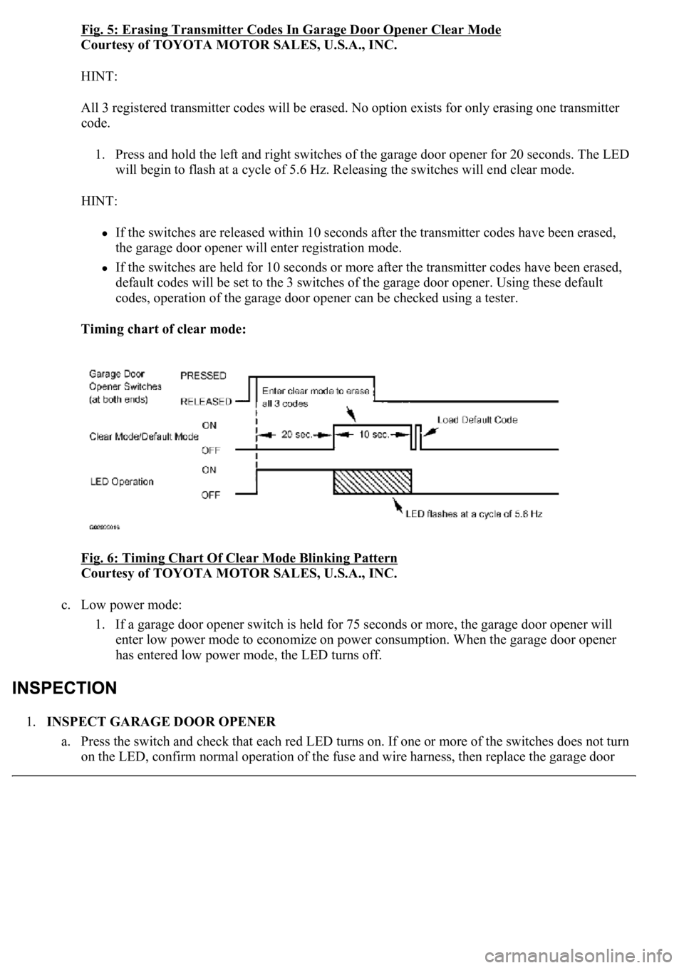
Fig. 5: Erasing Transmitter Codes In Garage Door Opener Clear Mode
Courtesy of TOYOTA MOTOR SALES, U.S.A., INC.
HINT:
All 3 registered transmitter codes will be erased. No option exists for only erasing one transmitter
code.
1. Press and hold the left and right switches of the garage door opener for 20 seconds. The LED
will begin to flash at a cycle of 5.6 Hz. Releasing the switches will end clear mode.
HINT:
If the switches are released within 10 seconds after the transmitter codes have been erased,
the garage door opener will enter registration mode.
If the switches are held for 10 seconds or more after the transmitter codes have been erased,
default codes will be set to the 3 switches of the garage door opener. Using these default
codes, operation of the garage door opener can be checked using a tester.
Timing chart of clear mode:
Fig. 6: Timing Chart Of Clear Mode Blinking Pattern
Courtesy of TOYOTA MOTOR SALES, U.S.A., INC.
c. Low power mode:
1. If a garage door opener switch is held for 75 seconds or more, the garage door opener will
enter low power mode to economize on power consumption. When the garage door opener
has entered low power mode, the LED turns off.
1.INSPECT GARAGE DOOR OPENER
a. Press the switch and check that each red LED turns on. If one or more of the switches does not turn
on the LED, confirm normal operation of the fuse and wire harness, then replace the
garage door