Page 227 of 4500

ROOM TEMP
Room temperature sensor / min.: -
6.5°C (20.3°F) max.: 57.25°C
(126.95°F)
Actual room temperature is displayed-
AMBI TEMP
SENSAmbient temperature sensor /
min.: -23.3°C (-9.94°F) max.:
65.95°C (150.71°F)Actual ambient temperature is
displayed-
EVAP TEMP
Evaporator temperature sensor /
min.: -29.7°C (-21.46°F) max.:
59.55°C (139.19°F)Actual evaporator temperature is
displayed-
SOLAR SENS-DSolar sensor (Driver side) / min.:
0 max.: 255Increases as brightness increases-
SOLAR SENS-PSolar sensor (Passenger side) /
min.: 0 max.: 255decreases as brightness increases-
COOLANT
TEMPEngine coolant temperature /
min.: 1.3°C (34.34°F) max.:
90.55°C (194.99°F)Actual engine coolant temperature is
displayed while the engine is warmed
up
-
DUCT TEMP-D
Duct sensor (Driver side) / min.: -
12.7°C (9.14°F) max.: 76.55°C
(169.79°F)Actual duct temperature is displayed
(Driver side)-
DUST TEMP-P
Duct sensor (Passenger side) /
min.: -12.7°C (9.14°F) max.:
76.55°C (169.79°F)Actual duct temperature is displayed
(Passenger side)-
SET TEMP-DSet temperature (Driver side) /
min.: 0 max.: 255Actual set temperature is displayed
(Driver side)-
SET TEMP-PSet temperature (Passenger
side) /min.: 0 max.: 255Actual set temperature is displayed
(Passenger side)-
ESTIMATE
TEMP-DEstimated temperature (Driver
side) / min.: -358.4°C (-613.12°F)
max.: 358.4°C (677.12°F)Actual estimated temperature is
displayed (Driver side)-
ESTIMATE
TEMP-PEstimated temperature (Passenger
side) / min.: -358.4°C (-613.12°F)
max.: 358.4°C (677.12°F)Actual estimated temperature is
displayed (Passenger side)-
A/I DAMP POSAir inlet damper position / min.: -
14% max.: 113.5%RECIRCULATION: Approx. 0%
FRESH: Approx. 100%-
A/B DAMP POS-
DCool air bypass damper position
(Driver side) / min.: -14% max.:
113.5%OPEN: Approx. 0 % SHUT: Approx.
100%-
A/B DAMP POS-
PCool air bypass damper position
(Passenger side) / min.: -14%
max.: 113.5%OPEN: Approx. 0 % SHUT: Approx.
100%-
ItemMeasurement Item / Display
(Range)Normal ConditionDiagnostic
Note
A/I DAMP
TARGAir inlet damper target / min.: -
14% max.: 113.5%RECIRCULATION: Approx. 0%
FRESH: Approx. 100% HALF-
RECIRCULATION: 43 to 99.5 %
-
Page 373 of 4500
Amplifier)
Courtesy of TOYOTA MOTOR SALES, U.S.A., INC.
NG: REPAIR OR REPLACE HARNESS OR CONNECTOR
OK: REPLACE AIR CONDITIONING AMPLIFIER (SEE REPLACEMENT
)
CIRCUIT DESCRIPTION
This circuit controls the amount of the coolant flowing to the heater core by a signal from the A/C amplifier,
and adjusts the temperature at the air outlets.
WIRING DIAGRAM
Fig. 132: Water Valve Control Servomotor Circuit
Courtesy of TOYOTA MOTOR SALES, U.S.A., INC.
Page 1779 of 4500

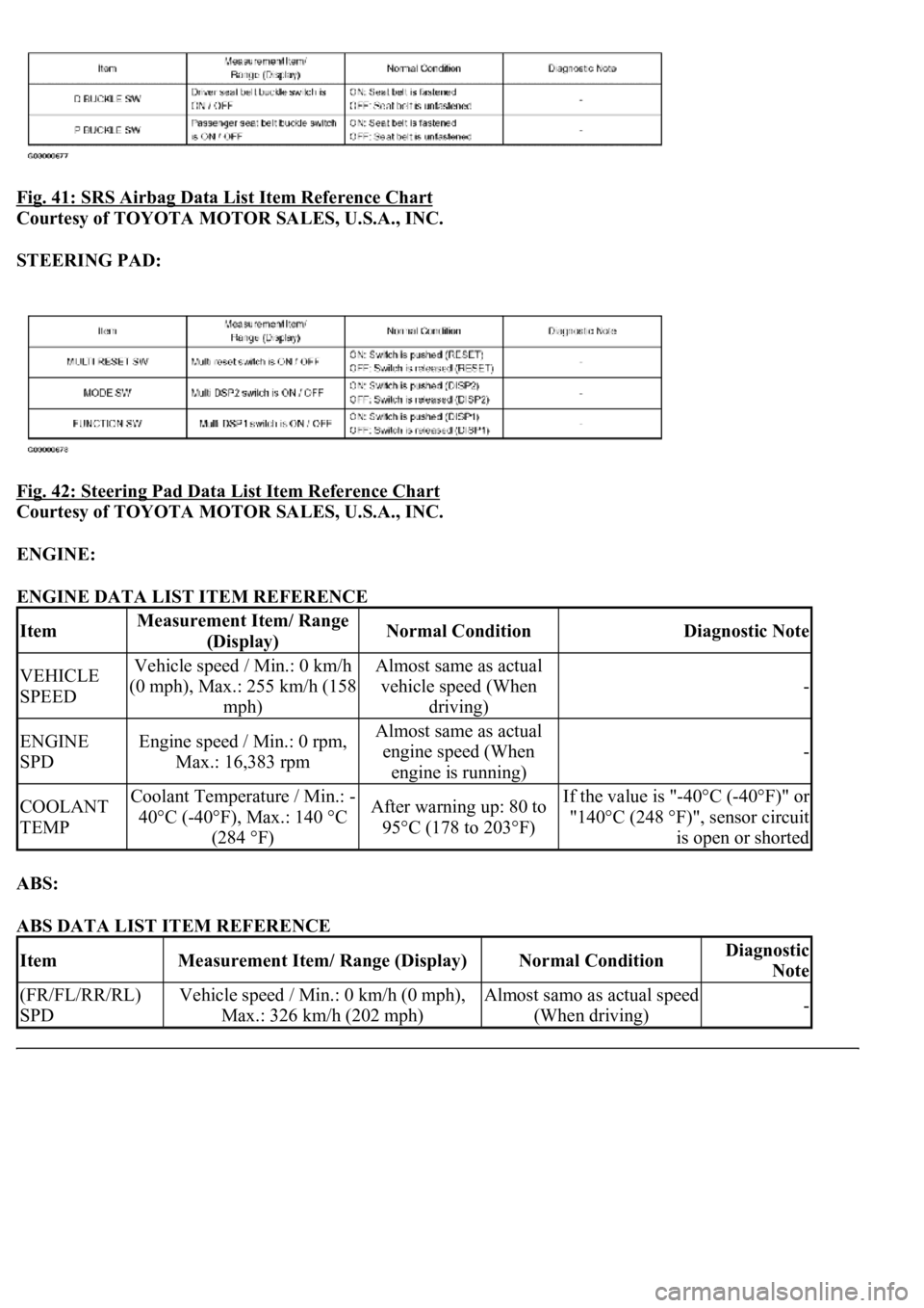
Fig. 41: SRS Airbag Data List Item Reference Chart
Courtesy of TOYOTA MOTOR SALES, U.S.A., INC.
STEERING PAD:
Fig. 42: Steering Pad Data List Item Reference Chart
Courtesy of TOYOTA MOTOR SALES, U.S.A., INC.
ENGINE:
ENGINE DATA LIST ITEM REFERENCE
ABS:
ABS DATA LIST ITEM REFERENCE
ItemMeasurement Item/ Range
(Display)Normal ConditionDiagnostic Note
VEHICLE
SPEEDVehicle speed / Min.: 0 km/h
(0 mph), Max.: 255 km/h (158
mph)Almost same as actual
vehicle speed (When
driving)
-
ENGINE
SPDEngine speed / Min.: 0 rpm,
Max.: 16,383 rpmAlmost same as actual
engine speed (When
engine is running)
-
COOLANT
TEMPCoolant Temperature / Min.: -
40°C (-40°F), Max.: 140 °C
(284 °F)After warning up: 80 to
95°C (178 to 203°F)If the value is "-40°C (-40°F)" or
"140°C (248 °F)", sensor circuit
is open or shorted
ItemMeasurement Item/ Range (Display)Normal ConditionDiagnostic
Note
(FR/FL/RR/RL)
SPDVehicle speed / Min.: 0 km/h (0 mph),
Max.: 326 km/h (202 mph)Almost samo as actual speed
(When driving)-
Page 1780 of 4500

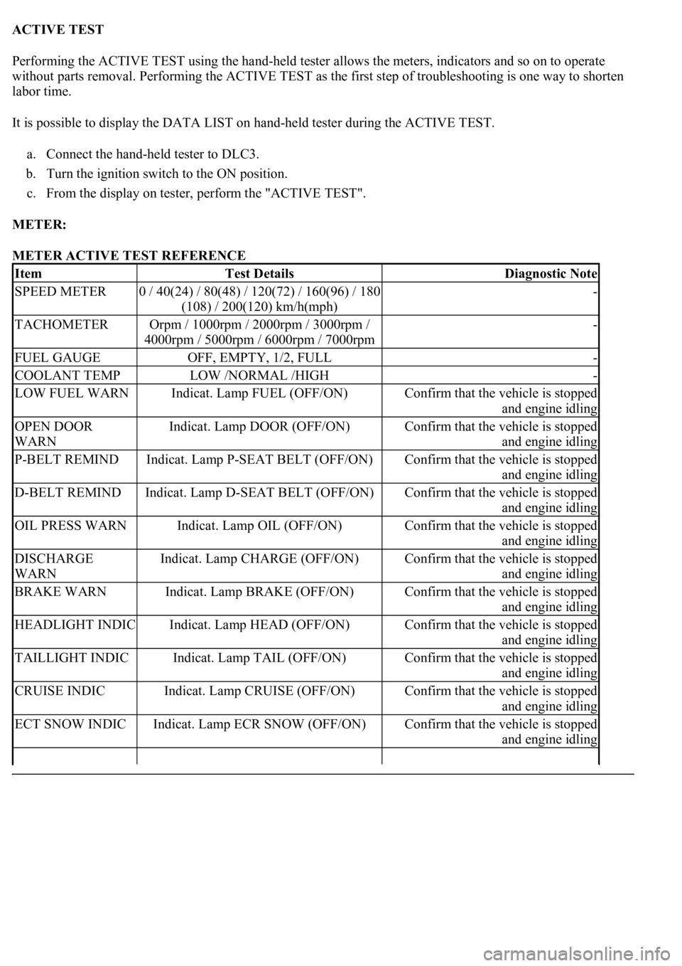
ACTIVE TEST
Performing the ACTIVE TEST using the hand-held tester allows the meters, indicators and so on to operate
without parts removal. Performing the ACTIVE TEST as the first step of troubleshooting is one way to shorten
labor time.
It is possible to display the DATA LIST on hand-held tester during the ACTIVE TEST.
a. Connect the hand-held tester to DLC3.
b. Turn the ignition switch to the ON position.
c. From the display on tester, perform the "ACTIVE TEST".
METER:
METER ACTIVE TEST REFERENCE
ItemTest DetailsDiagnostic Note
SPEED METER0 / 40(24) / 80(48) / 120(72) / 160(96) / 180
(108) / 200(120) km/h(mph)-
TACHOMETEROrpm / 1000rpm / 2000rpm / 3000rpm /
4000rpm / 5000rpm / 6000rpm / 7000rpm-
FUEL GAUGEOFF, EMPTY, 1/2, FULL-
COOLANT TEMPLOW /NORMAL /HIGH-
LOW FUEL WARNIndicat. Lamp FUEL (OFF/ON)Confirm that the vehicle is stopped
and engine idling
OPEN DOOR
WARNIndicat. Lamp DOOR (OFF/ON)Confirm that the vehicle is stopped
and engine idling
P-BELT REMINDIndicat. Lamp P-SEAT BELT (OFF/ON)Confirm that the vehicle is stopped
and engine idling
D-BELT REMINDIndicat. Lamp D-SEAT BELT (OFF/ON)Confirm that the vehicle is stopped
and engine idling
OIL PRESS WARNIndicat. Lamp OIL (OFF/ON)Confirm that the vehicle is stopped
and engine idling
DISCHARGE
WARNIndicat. Lamp CHARGE (OFF/ON)Confirm that the vehicle is stopped
and engine idling
BRAKE WARNIndicat. Lamp BRAKE (OFF/ON)Confirm that the vehicle is stopped
and engine idling
HEADLIGHT INDICIndicat. Lamp HEAD (OFF/ON)Confirm that the vehicle is stopped
and engine idling
TAILLIGHT INDICIndicat. Lamp TAIL (OFF/ON)Confirm that the vehicle is stopped
and engine idling
CRUISE INDICIndicat. Lamp CRUISE (OFF/ON)Confirm that the vehicle is stopped
and engine idling
ECT SNOW INDICIndicat. Lamp ECR SNOW (OFF/ON)Confirm that the vehicle is stopped
and engine idling
Page 1810 of 4500
Fig. 63: Identifying Fuel Sender Gauge Assy And Luggage Room Junction Block Assy Connector
Terminals
Courtesy of TOYOTA MOTOR SALES, U.S.A., INC.
NG: REPAIR OR REPLACE HARNESS OR CONNECTOR
OK: REPLACE LUGGAGE ROOM JUNCTION BLOCK ASSY
WIRING DIAGRAM
Fig. 64: Water Temperature Receiver Gauge Wiring Diagram
Courtesy of TOYOTA MOTOR SALES, U.S.A., INC.
INSPECTION PROCEDURE
HINT:
If there is an open or short in the engine coolant temperature sensor circuit, the ECM outputs DTCs. Perform
troubleshooting with the "SFI System 10-2".
1.PERFORM ACTIVE TEST BY HAND-HELD TESTER
a. Operate the hand-held tester according to the steps on the display and select the "ACTIVE TEST".
METER:
ACTIVE TEST REFERENCE
Page 1811 of 4500
OK:
Needle indication is normal.
NG: REPLACE COMBINATION METER ASSY (SEE OVERHAUL
)
OK: GO TO NEXT STEP
2.READ VALUE OF HAND-HELD TESTER (ENGINE COOLANT)
a. Operate the hand-held tester according to the steps on the display and select the "DATA LIST".
ENGINE:
DATA LIST REFERENCE
OK:
Coolant temperature displayed on the tester is between 80°C (176°F) and 95°C (203°F) after
warning up.
NG: GO TO ENGINE CONTROL SYSTEM (SEE REPLACEMENT
)
OK: GO TO NEXT STEP
3.REPLACE COMBINATION METER ASSY
OK:
Normal operation
NG: GO TO ENGINE CONTROL SYSTEM (SEE REPLACEMENT
)
OK: END
WIRING DIAGRAM
ItemTest DetailsDiagnostic Note
COOLANT TEMPLOW /NORMAL /HI-
ItemMeasurement Item/ Range
(Display)Normal ConditionDiagnostic Note
COOLANT
TEMPCoolant Temperature / Min.: -
40°C (-40°F), Max.: 140°C
(284 °F)After warming up: 80
to 95°C (176 to 203°
F)If the value is "-40°C (-40°F)" or
"140°C (284°F)", sensor circuit is
open or shorted.
Page 1849 of 4500
ON-VEHICLE INSPECTION
1.CHECK COOLING SYSTEM FOR LEAKS
a. Fill the radiator with coolant and attach a radiator cap tester.
Fig. 1: Checking Cooling System For Leaks
Courtesy of TOYOTA MOTOR SALES, U.S.A., INC.
b. Warm up the engine.
c. Using a radiator cap tester, increase the pressure inside the radiator to 137 kPa (1.4 kgf/cm
2, 19.9
Page 1850 of 4500

psi), and check that the pressure does not drop.
If the pressure drops, check the hoses, radiator and water pump for leaks. If no external leaks are found,
check the heater core, cylinder block and head.
2.CHECK ENGINE COOLANT LEVEL AT RESERVOIR
a. Check that the engine coolant level is between the LOW and FULL lines when the engine is cold.
If the engine coolant is low, check for leaks and add "TOYOTA Super Long Life Coolant" to the
FULL line.
If "TOYOTA Super Long Life Coolant" is not available, use a similar high quality ethylene glycol
based non-silicate, non-amino, non-nitrite and non-borate coolant with long-life hybrid organic acid
technology. Do not substitute plain water for engine coolant.
3.CHECK ENGINE COOLANT QUALITY
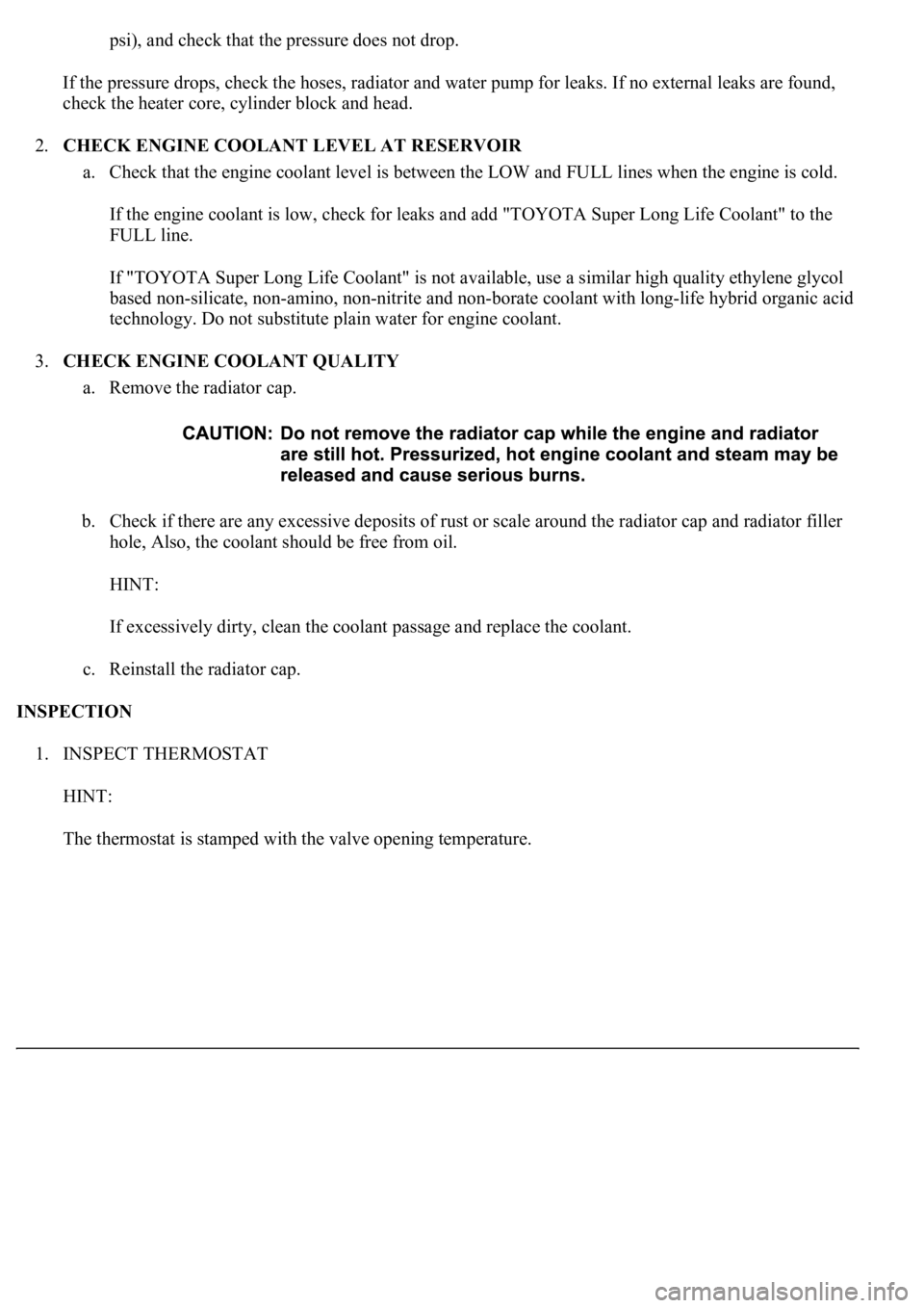
a. Remove the radiator cap.
b. Check if there are any excessive deposits of rust or scale around the radiator cap and radiator filler
hole, Also, the coolant should be free from oil.
HINT:
If excessively dirty, clean the coolant passage and replace the coolant.
c. Reinstall the radiator cap.
INSPECTION
1. INSPECT THERMOSTAT
HINT:
The thermostat is stamped with the valve openin
g temperature.