Page 2 of 4500
Fluid SpecificationsSee FLUIDS under MAINTENANCE tab.
Flywheel/Flex Plate
(Drive Plate) TorqueStep1: 49 N.m (500 kgf.cm, 36 ft lbs)
Step2: Turn 90°
Fuel System
Pressure
Specification304 to 343 kPa (3.1 to 3.5 kgf/cm2 , 44 to 50 psi)
Fuel Pressure Test
ProcedureON-VEHICLE INSPECTION
Fuel Filter
LocationCOMPONENTS
Ignition
Firing Order &
Cylinder
IdentificationFIRING ORDER & CYLINDER IDENTIFICATION
Spark Plug
TypeND SK20R11
NGK 1FR6A11
GapStandard electrode gap: 1.0 - 1.1 mm (0.039 - 0.043 in.)
Maximum electrode gap: 1.3 mm (0.051 in.)
Torque7.5 N.m (76 kgf.cm, 66 ft.lbf)
Starting
StarterSERVICE DATA
TorqueTORQUE SPECIFICATION
Wheel Alignment
Front
Adjustment
SpecificationsSERVICE DATA
TorqueTORQUE SPECIFICATION
Rear
Adjustment
SpecificationsSERVICE DATA
TorqueTORQUE SPECIFICATION
Wheel & Tire
Wheel Lug Nut
Torque103 N.m (1,050 kgf.cm 76 ft.lbf)
Page 2670 of 4500

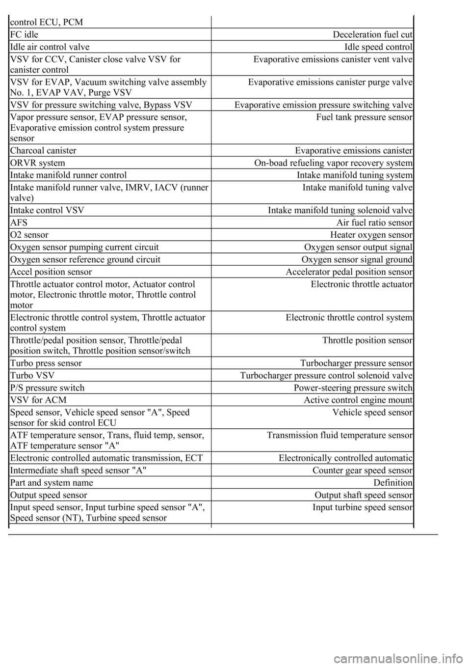
control ECU, PCM
FC idleDeceleration fuel cut
Idle air control valveIdle speed control
VSV for CCV, Canister close valve VSV for
canister controlEvaporative emissions canister vent valve
VSV for EVAP, Vacuum switching valve assembly
No. 1, EVAP VAV, Purge VSVEvaporative emissions canister purge valve
VSV for pressure switching valve, Bypass VSVEvaporative emission pressure switching valve
Vapor pressure sensor, EVAP pressure sensor,
Evaporative emission control system pressure
sensorFuel tank pressure sensor
Charcoal canisterEvaporative emissions canister
ORVR systemOn-boad refueling vapor recovery system
Intake manifold runner controlIntake manifold tuning system
Intake manifold runner valve, IMRV, IACV (runner
valve)Intake manifold tuning valve
Intake control VSVIntake manifold tuning solenoid valve
AFSAir fuel ratio sensor
O2 sensorHeater oxygen sensor
Oxygen sensor pumping current circuitOxygen sensor output signal
Oxygen sensor reference ground circuitOxygen sensor signal ground
Accel position sensorAccelerator pedal position sensor
Throttle actuator control motor, Actuator control
motor, Electronic throttle motor, Throttle control
motorElectronic throttle actuator
Electronic throttle control system, Throttle actuator
control systemElectronic throttle control system
Throttle/pedal position sensor, Throttle/pedal
position switch, Throttle position sensor/switchThrottle position sensor
Turbo press sensorTurbocharger pressure sensor
Turbo VSVTurbocharger pressure control solenoid valve
P/S pressure switchPower-steering pressure switch
VSV for ACMActive control engine mount
Speed sensor, Vehicle speed sensor "A", Speed
sensor for skid control ECUVehicle speed sensor
ATF temperature sensor, Trans, fluid temp, sensor,
ATF temperature sensor "A"Transmission fluid temperature sensor
Electronic controlled automatic transmission, ECTElectronically controlled automatic
Intermediate shaft speed sensor "A"Counter gear speed sensor
Part and system nameDefinition
Output speed sensorOutput shaft speed sensor
<002c00510053005800570003005600530048004800470003005600480051005600520055000f0003002c005100530058005700030057005800550045004c005100480003005600530048004800470003005600480051005600520055000300050024000500
0f0003[
Speed sensor (NT), Turbine speed sensorInput turbine speed sensor
Page 2905 of 4500
LS 430
CEC
Computerized Engine Controls
EVAP
Fuel Evaporative System
EVAP-CCVVSV
EVAP Canister Closed Valve Vacuum Switching Valve
EVAP-VC
EVAP Vapor Canister
EVAP-VPS
EVAP Vapor Pressure Sensor
EVAP-VPSVSV
Vapor Pressure Sensor Vacuum Switching Valve
Engine & Fuel System(1) Emission Control Systems & Devices
2006
4.3L (261") V8 SFIPCV, EVAP, (2) TWC, FR, SPK, (3) HO2S, CEC,
MIL, EVAP-VSV, EVAP-VC, EVAP-VPS, EVAP-
VPSVSV, EVAP-CCVVSV, ORVR-COV, ORVR-
OCKV
(1)For quick reference, major emission control systems and devices are listed in bold type; components
and other related devices are listed in light type.
(2)Equipped with 3.
(3)Equipped with 4.
Page 3313 of 4500

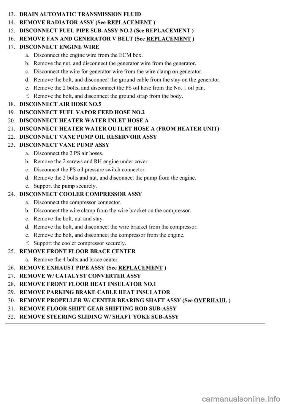
13.DRAIN AUTOMATIC TRANSMISSION FLUID
14.REMOVE RADIATOR ASSY (See REPLACEMENT
)
15.DISCONNECT FUEL PIPE SUB-ASSY NO.2 (See REPLACEMENT
)
16.REMOVE FAN AND GENERATOR V BELT (See REPLACEMENT
)
17.DISCONNECT ENGINE WIRE
a. Disconnect the engine wire from the ECM box.
b. Remove the nut, and disconnect the generator wire from the generator.
c. Disconnect the wire for generator wire from the wire clamp on generator.
d. Remove the bolt, and disconnect the ground cable from the stay on the generator.
e. Remove the 2 bolts, and disconnect the PS oil hose from the No. 1 oil pan.
f. Remove the bolt, and disconnect the ground strap from the body.
18.DISCONNECT AIR HOSE NO.5
19.DISCONNECT FUEL VAPOR FEED HOSE NO.2
20.DISCONNECT HEATER WATER INLET HOSE A
21.DISCONNECT HEATER WATER OUTLET HOSE A (FROM HEATER UNIT)
22.DISCONNECT VANE PUMP OIL RESERVOIR ASSY
23.DISCONNECT VANE PUMP ASSY
a. Disconnect the 2 PS air hoses.
b. Remove the 2 screws and RH engine under cover.
c. Disconnect the PS oil pressure switch connector.
d. Remove the 2 bolts and nut, and disconnect the pump from the engine.
e. Support the pump securely.
24.DISCONNECT COOLER COMPRESSOR ASSY
a. Disconnect the compressor connector.
b. Disconnect the wire clamp from the wire bracket on the compressor.
c. Remove the bolt, nut and stay.
d. Remove the bolt, and disconnect the wire bracket from the compressor.
e. Remove the bolt, and disconnect the compressor from the engine.
f. Support the cooler compressor securely.
25.REMOVE FRONT FLOOR BRACE CENTER
a. Remove the 4 bolts and brace center.
26.REMOVE EXHAUST PIPE ASSY (See REPLACEMENT
)
27.REMOVE W/ CATALYST CONVERTER ASSY
28.REMOVE FRONT FLOOR HEAT INSULATOR NO.1
29.REMOVE PARKING BRAKE CABLE HEAT INSULATOR
30.REMOVE PROPELLER W/ CENTER BEARING SHAFT ASSY (See OVERHAUL
)
31.REMOVE FLOOR SHIFT GEAR SHIFTING ROD SUB-ASSY
32.REMOVE STEERING SLIDING W/ SHAFT YOKE SUB-ASSY
Page 4103 of 4500

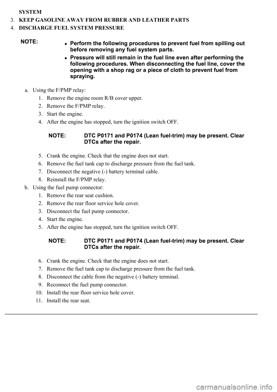
SYSTEM
3.KEEP GASOLINE AWAY FROM RUBBER AND LEATHER PARTS
4.DISCHARGE FUEL SYSTEM PRESSURE
a. Using the F/PMP relay:
1. Remove the engine room R/B cover upper.
2. Remove the F/PMP relay.
3. Start the engine.
4. After the engine has stopped, turn the ignition switch OFF.
5. Crank the engine. Check that the engine does not start.
6. Remove the fuel tank cap to discharge pressure from the fuel tank.
7. Disconnect the negative (-) battery terminal cable.
8. Reinstall the F/PMP relay.
b. Using the fuel pump connector:
1. Remove the rear seat cushion.
2. Remove the rear floor service hole cover.
3. Disconnect the fuel pump connector.
4. Start the engine.
5. After the engine has stopped, turn the ignition switch OFF.
6. Crank the engine. Check that the engine does not start.
7. Remove the fuel tank cap to discharge pressure from the fuel tank.
8. Disconnect the cable from the negative (-) battery terminal.
9. Reconnect the fuel pump connector.
10. Install the rear floor service hole cover.
11. Install the rear seat.
Page 4104 of 4500
5.FUEL SYSTEM
a. When disconnecting the high fuel pressure line, a large amount of gasoline will spill out. Observe
these procedures:
1. Perform the "DISCHARGE FUEL SYSTEM PRESSURE" procedures above. Put a container
under the connection.
2. Disconnect the fuel tube.
3. Drain the fuel remaining inside the fuel tube.
4. Protect the disconnected fuel tube from damage and foreign material by covering it with a
plastic bag.
b. When connecting the union bolt (fuel pressure pulsation damper) on the high pressure pipe union,
observe these procedures:
1. Always use 2 new gaskets.
2. Tighten the union bolt by hand.
Fig. 5: Tightening Union Bolt By Hand
Courtesy of TOYOTA MOTOR SALES, U.S.A., INC.
3. Using SST, tighten the union bolt to the specified torque.
SST 09612-24014 (09617-24011)
Torque:
Page 4113 of 4500
Fig. 15: Connecting Hand-Held Tester DLC3
Courtesy of TOYOTA MOTOR SALES, U.S.A., INC.
c. Select the ACTIVE TEST mode on the hand-held tester.
d. Please refer to the hand-held tester operator's manual for further details.
e. Check that there is pressure in the fuel inlet hose from the fuel filter.
HINT:
If there is fuel pressure, you will hear the sound of fuel flowing. If there is no pressure, check the
fusible link, fuses, EFI MAIN relay, fuel pump, ECM and wiring connections.
f. Turn the ignition switch to LOCK.
g. Disconnect the hand-held tester from the DLC3.
2.CHECK FUEL PRESSURE
a. Check that the battery positive voltage is above 12 V.
b. Disconnect the negative (-) terminal cable from the battery.
c. Remove the fuel pressure pulsation damper from the RH delivery pipe (see REPLACEMENT
).
d. Install the fuel pipe sub-ass
y No. 2 and SST (pressure gauge) to the delivery pipe with the 3 lower
Page 4114 of 4500
gaskets and SST (union bolt).
SST 09268-45014 (09268-41190, 90405-06167)
Torque: 39 N.m (400 kgf.cm, 29 ft.lbf)
Fig. 16: Checking Fuel Pressure
Courtesy of TOYOTA MOTOR SALES, U.S.A., INC.
e. Wipe off any splattered gasoline.
f. Reconnect the negative (-) terminal cable to the battery.
g. Connect the hand-held tester (with CAN VIM) to the DLC3 (see step 1 (a) b c d to (e)).
h. Measure the fuel pressure.
Fuel pressure:
304 to 343 kPa (3.1 to 3.5 kgf/cm2, 44 to 50 psi)
If pressure is high, replace the fuel pressure regulator.
If pressure is low, check the fuel hoses, fuel hose connections, fuel pump, fuel filter and fuel