2003 LEXUS LS430 mirror
[x] Cancel search: mirrorPage 210 of 4500

Fig. 6: Air Conditioning System Diagram (2 Of 2)
Courtesy of TOYOTA MOTOR SALES, U.S.A., INC.
1.GENERAL
a. The air conditioning system has the following features:
In compliance with the temperature set at the temperature control switch, the neural network
control calculates the outlet temperature based on the input signals from various sensors. In
addition, corrections in accordance with the signals from the evaporative temperature sensor
and the water temperature sensor are added to control the outlet air temperature.
Controls the front and rear blower motors in accordance with the airflow volume that has
been calculated by the neural network control based on the input signals from various
sensors.
Automatically switches the outlets in accordance with the outlet mode ratio that has been
calculated by the neural network control based on the input signals from various sensors.
Automatically controls the air inlet control damper in accordance with the airflow volume
that has been calculated by the neural network control.
Turns the compressor on/off and controls the discharge capacity based on the signals from
various sensors.
Based on the signals from the ambient temperature sensor, this control calculates the outside
temperature, which is then corrected in the air conditioner ECU, and shown in the multi-
information display in the combination meter.
Switched the rear defogger and outside rear view mirror heaters on for 15 minutes when the
rear defogger switch is switched on. Switched them off if the switch is pressed while they are
operating.
Controls the orientation and the angle of the front center register based on the input signals
from various sensors and on the outlet mode.
Determines whether the clean air filter (for the front A/C) is clogged by monitoring the air
inlets, and airflow volume.
The A/C amplifier automatically controls the air inlets based on the signals from the smog
ventilation sensor.
Improves the air quality by linking the air inlet control damper and the blower motor (for the
rear A/C and air purifier), based on the signals from the exhaust gas sensor and the smoke
sensor.
Checks the sensors in accordance with operation of the air conditioner switches.
2.MODEL POSITION AND DAMPER OPERATION
Page 980 of 4500
3.REMOVE SEAT TRACK COVER LH
4.REMOVE SEAT TRACK BRACKET COVER OUTER FR
5.REMOVE SEAT TRACK BRACKET COVER INNER FR
6.REMOVE FRONT SEAT ASSY LH
7.REMOVE INSTRUMENT CLUSTER FINISH PANEL END
8.REMOVE INSTRUMENT CLUSTER FINISH PANEL CENTER LOWER
9.REMOVE INSTRUMENT PANEL UNDER COVER SUB-ASSY NO.1 (SEE REPLACEMENT
)
10.REMOVE COIN BOX ASSY
11.REMOVE OUTER MIRROR SWITCH ASSY
12.REMOVE INSTRUMENT PANEL SAFETY PAD SUB-ASSY NO.1 (SEE REPLACEMENT
)
13.REMOVE INSTRUMENT PANEL UNDER COVER SUB-ASSY No.2 (SEE REPLACEMENT
)
14.REMOVE FR DOOR SCUFF PLATE LH (SEE REPLACEMENT
)
15.REMOVE FLOOR CARPET ASSY FRONT
16.CHECK AND ADJUST BRAKE PEDAL HEIGHT
a. Check brake pedal height.
Pedal height from asphalt sheet:
165.1 to 175.1 mm (6.49 to 6.89 in.)
b. If necessary, adjust brake pedal height.
1. Disconnect the connector from the stop lamp switch assy.
2. Loosen the stop lamp switch lock nut and remove the stop lamp switch assy.
3. Loosen the push rod lock nut.
4. Adjust the pedal height by turning the pedal push rod.
5. Tighten the push rod lock nut.
Torque: 26 N.m (265 kgf.cm, 19 ft.lbf)
6. Install the stop lamp switch assy.
7. Connect the stop lamp switch assy connector.
8. Push the brake pedal in 5 to 10 mm (0.20 to 0.39 in.), and turn the stop lamp switch assy to lock the
<0051005800570003004c005100030057004b00480003005300520056004c0057004c005200510003005a004b00480055004800030057004b0048000300560057005200530003004f0044005000530003004a00520048005600030052004900490011000300
03[
9. After installation, push the brake pedal in 5 to 10 mm (0.20 to 0.39 in.), and check that the stop
lamp comes on.
10. Tighten the stop lamp switch lock nut.
Torque: 17 N.m (173 kgf.cm, 12 ft.lbf)
If the stop lamp does not come on, repeat the steps in (
b).
Page 985 of 4500
23.INSTALL OUTER MIRROR SWITCH ASSY
24.INSTALL COIN BOX
25.INSTALL INSTRUMENT PANEL UNDER COVER NO.1 (SEE REPLACEMENT
)
26.INSTALL CLUSTER FINISH PANEL CENTER LOWER
27.INSTALL INSTRUMENT CLUSTER FINISH PANEL END
28.INSTALL SEAT ASSY FR LH
29.INSTALL SEAT TRACK BRACKET COVER INNER FRONT
30.INSTALL SEAT TRACK BRACKET COVER OUTER FRONT
31.INSTALL SEAT TRACK OUTER COVER LH
32.INSTALL SEAT TRACK COVER RH
33.INSTALL SEAT BELT ANCHOR COVER CAP LH
OVERHAUL
1.DISCONNECT BATTERY NEGATIVE TERMINAL
2.PLACE FRONT WHEELS FACING STRAIGHT AHEAD
3.REMOVE SWITCH & VOLUME CASE
4.REMOVE STEERING WHEEL COVER LOWER NO.2
5.REMOVE HORN BUTTON ASSY (SEE OVERHAUL
)
6.REMOVE STEERING WHEEL ASSY (SEE OVERHAUL
)
<00360036003700030013001c001c001800130010001800130013001400160003000b0013001c001c00180014001000130018001300140013000f00030013001c001c00180015001000130018001300140013000f00030013001c001c001800160010001300
18001300150013000f00030013001c001c0018001700100013[5021)
7.REMOVE STEERING COLUMN COVER (SEE OVERHAUL
)
8.REMOVE SPIRAL CABLE SUB-ASSY (SEE REPLACEMENT
)
9.REMOVE TURN SIGNAL SWITCH ASSY (SEE REPLACEMENT
)
10.REMOVE INSTRUMENT CLUSTER FINISH PANEL CENTER LOWER
11.REMOVE INSTRUMENT CLUSTER FINISH PANEL END
12.REMOVE INSTRUMENT PANEL UNDER COVER SUB-ASSY NO.1 (SEE REPLACEMENT
)
13.REMOVE COIN BOX ASSY
14.REMOVE OUTER MIRROR SWITCH ASSY
15.REMOVE INSTRUMENT PANEL SAFETY PAD SUB-ASSY NO.1 (SEE REPLACEMENT
)
16.REMOVE INSTRUMENT PANEL AIR BAG ASSY LOWER NO.1 (SEE REPLACEMENT
)
17.REMOVE INSTRUMENT PANEL UNDER COVER SUB-ASSY NO.2 (SEE REPLACEMENT
)
18.REMOVE INSTRUMENT CLUSTER FINISH PANEL (SEE REPLACEMENT
)
19.REMOVE COMBINATION METER ASSY (SEE OVERHAUL
)
20.REMOVE PUSH ROD PIN
a. Disconnect the stop lamp switch connector and brake pedal load sensing switch connector.
Page 1005 of 4500
34.CHECK AND ADJUST BRAKE PEDAL HEIGHT (SEE ON-VEHICLE INSPECTION )
35.CHECK PEDAL FREE PLAY (SEE ON
-VEHICLE INSPECTION )
36.CHECK PEDAL RESERVE DISTANCE (SEE ON
-VEHICLE INSPECTION )
37.INSTALL COMBINATION METER ASSY (SEE OVERHAUL
)
38.INSTALL INSTRUMENT CLUSTER FINISH PANEL (SEE REPLACEMENT
)
39.INSTALL INSTRUMENT PANEL UNDER COVER SUB-ASSY NO.2 (SEE REPLACEMENT
)
40.INSTALL INSTRUMENT PANEL AIR BAG ASSY LOWER NO.1 (SEE REPLACEMENT
)
41.INSTALL INSTRUMENT PANEL SAFETY PAD SUB-ASSY NO.1 (SEE REPLACEMENT
)
42.INSTALL OUTER MIRROR SWITCH ASSY
43.INSTALL COIN BOX ASSY
44.INSTALL INSTRUMENT PANEL UNDER COVER SUB-ASSY NO.1 (SEE REPLACEMENT
)
45.INSTALL INSTRUMENT CLUSTER FINISH PANEL CENTER LOWER
46.INSTALL INSTRUMENT CLUSTER FINISH PANEL END
47.INSTALL TURN SIGNAL SWITCH ASSY (SEE REPLACEMENT
)
48.INSTALL SPIRAL CABLE SUB-ASSY (SEE REPLACEMENT
)
49.INSTALL STEERING COLUMN COVER (SEE OVERHAUL
)
50.INSTALL STEERING WHEEL ASSY (SEE OVERHAUL
)
<00360036003700030013001c001c001800130010001800130013001400160003000b0013001c001c00180014001000130018001300140013000f00030013001c001c00180015001000130018001300140013000f00030013001c001c001800160010001300
18001300150013000f00030013001c001c0018001700100013[5021)
51.INSTALL HORN BUTTON ASSY (SEE OVERHAUL
)
52.INSTALL STEERING WHEEL COVER LOWER NO.2
53.INSTALL SWITCH & VOLUME CASE
54.CONNECT BATTERY NEGATIVE TERMINAL
55.INSPECT SRS WARNING LIGHT (SEE DIAGNOSIS SYSTEM
)
56.PERFORM INITIALIZATION (SEE PRECAUTION
)
OVERHAUL
1.REMOVE ENGINE ROOM SIDE COVER
2.SEPARATE ENGINE ROOM NO.3 R/B
a. Remove the bolt and separate the engine room No.3 R/B.
3.DRAIN BRAKE FLUID
a. Draw out fluid with syringe.
4.REMOVE BRAKE MASTER CYLINDER SUB-ASSY
a. Remove the clamp from the 2 brake tubes.
Page 1027 of 4500
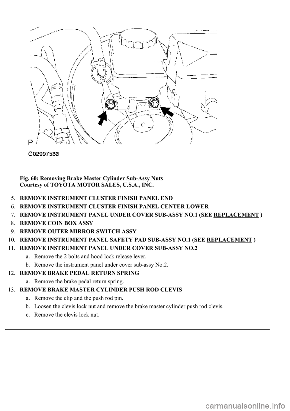
Fig. 60: Removing Brake Master Cylinder Sub-Assy Nuts
Courtesy of TOYOTA MOTOR SALES, U.S.A., INC.
5.REMOVE INSTRUMENT CLUSTER FINISH PANEL END
6.REMOVE INSTRUMENT CLUSTER FINISH PANEL CENTER LOWER
7.REMOVE INSTRUMENT PANEL UNDER COVER SUB-ASSY NO.1 (SEE REPLACEMENT
)
8.REMOVE COIN BOX ASSY
9.REMOVE OUTER MIRROR SWITCH ASSY
10.REMOVE INSTRUMENT PANEL SAFETY PAD SUB-ASSY NO.1 (SEE REPLACEMENT
)
11.REMOVE INSTRUMENT PANEL UNDER COVER SUB-ASSY NO.2
a. Remove the 2 bolts and hood lock release lever.
b. Remove the instrument panel under cover sub-assy No.2.
12.REMOVE BRAKE PEDAL RETURN SPRING
a. Remove the brake pedal return spring.
13.REMOVE BRAKE MASTER CYLINDER PUSH ROD CLEVIS
a. Remove the clip and the push rod pin.
b. Loosen the clevis lock nut and remove the brake master cylinder push rod clevis.
c. Remove the clevis lock nut.
Page 1036 of 4500
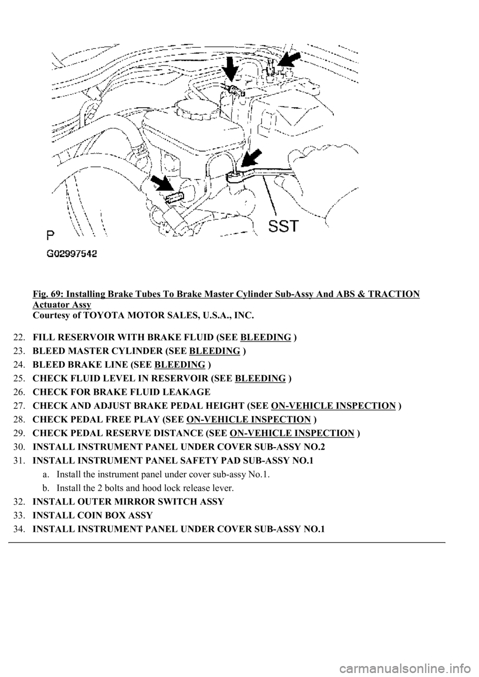
Fig. 69: Installing Brake Tubes To Brake Master Cylinder Sub-Assy And ABS & TRACTION
Actuator Assy
Courtesy of TOYOTA MOTOR SALES, U.S.A., INC.
22.FILL RESERVOIR WITH BRAKE FLUID (SEE BLEEDING
)
23.BLEED MASTER CYLINDER (SEE BLEEDING
)
24.BLEED BRAKE LINE (SEE BLEEDING
)
25.CHECK FLUID LEVEL IN RESERVOIR (SEE BLEEDING
)
26.CHECK FOR BRAKE FLUID LEAKAGE
27.CHECK AND ADJUST BRAKE PEDAL HEIGHT (SEE ON
-VEHICLE INSPECTION )
28.CHECK PEDAL FREE PLAY (SEE ON
-VEHICLE INSPECTION )
29.CHECK PEDAL RESERVE DISTANCE (SEE ON
-VEHICLE INSPECTION )
30.INSTALL INSTRUMENT PANEL UNDER COVER SUB-ASSY NO.2
31.INSTALL INSTRUMENT PANEL SAFETY PAD SUB-ASSY NO.1
a. Install the instrument panel under cover sub-assy No.1.
b. Install the 2 bolts and hood lock release lever.
32.INSTALL OUTER MIRROR SWITCH ASSY
33.INSTALL COIN BOX ASSY
34.INSTALL INSTRUMENT PANEL UNDER COVER SUB-ASSY NO.1
Page 1107 of 4500
SYSTEM INDEX
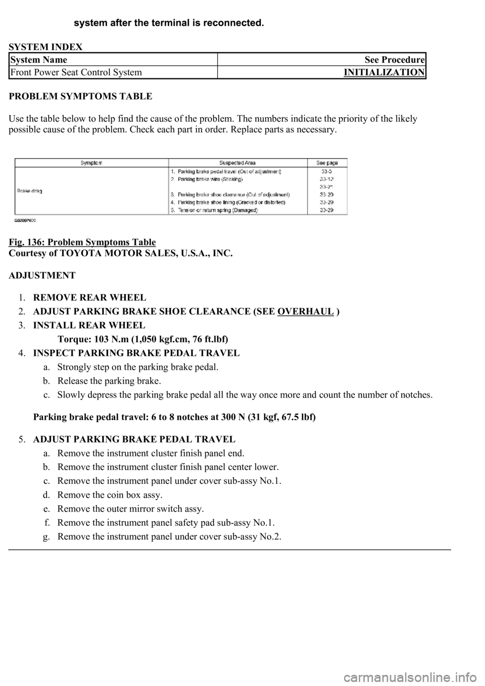
PROBLEM SYMPTOMS TABLE
<00380056004800030057004b00480003005700440045004f0048000300450048004f0052005a0003005700520003004b0048004f005300030049004c0051004700030057004b004800030046004400580056004800030052004900030057004b0048000300
53005500520045004f00480050001100030037004b00480003[numbers indicate the priority of the likely
possible cause of the problem. Check each part in order. Replace parts as necessary.
Fig. 136: Problem Symptoms Table
Courtesy of TOYOTA MOTOR SALES, U.S.A., INC.
ADJUSTMENT
1.REMOVE REAR WHEEL
2.ADJUST PARKING BRAKE SHOE CLEARANCE (SEE OVERHAUL
)
3.INSTALL REAR WHEEL
Torque: 103 N.m (1,050 kgf.cm, 76 ft.lbf)
4.INSPECT PARKING BRAKE PEDAL TRAVEL
a. Strongly step on the parking brake pedal.
b. Release the parking brake.
c. Slowly depress the parking brake pedal all the way once more and count the number of notches.
Parking brake pedal travel: 6 to 8 notches at 300 N (31 kgf, 67.5 lbf)
5.ADJUST PARKING BRAKE PEDAL TRAVEL
a. Remove the instrument cluster finish panel end.
b. Remove the instrument cluster finish panel center lower.
c. Remove the instrument panel under cover sub-assy No.1.
d. Remove the coin box assy.
e. Remove the outer mirror switch assy.
f. Remove the instrument panel safety pad sub-assy No.1.
g. Remove the instrument panel under cover sub-assy No.2.
System NameSee Procedure
Front Power Seat Control SystemINITIALIZATION
Page 1109 of 4500
p. Install the outer mirror switch assy.
q. Install the coin box assy.
r. Install the instrument panel under cover sub-assy No.1.
s. Install the instrument cluster finish panel center lower.
t. Install the instrument cluster finish panel end.
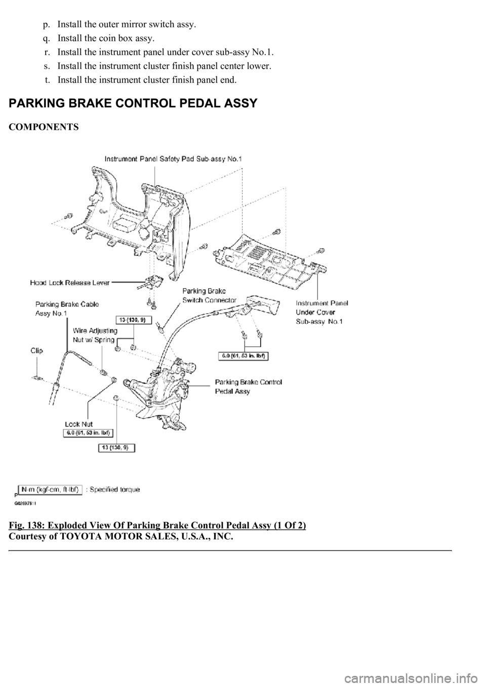
COMPONENTS
Fig. 138: Exploded View Of Parking Brake Control Pedal Assy (1 Of 2)
Courtesy of TOYOTA MOTOR SALES, U.S.A., INC.