2003 LEXUS LS430 washer fluid
[x] Cancel search: washer fluidPage 1744 of 4500
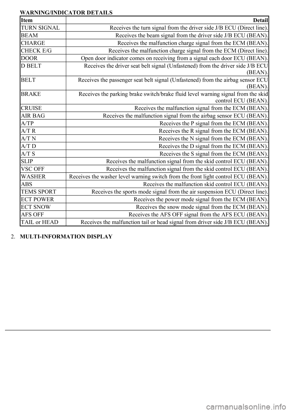
WARNING/INDICATOR DETAILS
2.MULTI-INFORMATION DISPLAY
ItemDetail
TURN SIGNALReceives the turn signal from the driver side J/B ECU (Direct line).
BEAMReceives the beam signal from the driver side J/B ECU (BEAN).
CHARGEReceives the malfunction charge signal from the ECM (BEAN).
CHECK E/GReceives the malfunction charge signal from the ECM (Direct line).
DOOROpen door indicator comes on receiving from a signal each door ECU (BEAN).
D BELTReceives the driver seat belt signal (Unfastened) from the driver side J/B ECU
(BEAN).
BELTReceives the passenger seat belt signal (Unfastened) from the airbag sensor ECU
(BEAN).
BRAKEReceives the parking brake switch/brake fluid level warning signal from the skid
control ECU (BEAN).
CRUISEReceives the malfunction signal from the ECM (BEAN).
AIR BAGReceives the malfunction signal from the airbag sensor ECU (BEAN).
A/TPReceives the P signal from the ECM (BEAN).
A/T RReceives the R signal from the ECM (BEAN).
A/T NReceives the N signal from the ECM (BEAN).
A/T DReceives the D signal from the ECM (BEAN).
A/T SReceives the S signal from the ECM (BEAN).
SLIPReceives the malfunction signal from the skid control ECU (BEAN).
VSC OFFReceives the malfunction signal from the skid control ECU (BEAN).
WASHERReceives the washer level warning switch from the front light control ECU (BEAN).
ABSReceives the malfunction skid control ECU (BEAN).
TEMS SPORTReceives the sports mode signal from the air suspension ECU (Direct line).
ECT POWERReceives the power mode signal from the ECM (BEAN).
ECT SNOWReceives the snow mode signal from the ECM (BEAN).
AFS OFFReceives the AFS OFF signal from the AFS ECU (BEAN).
TAIL or HEADReceives the malfunction tail or head signal from driver side J/B ECU (BEAN).
Page 1848 of 4500
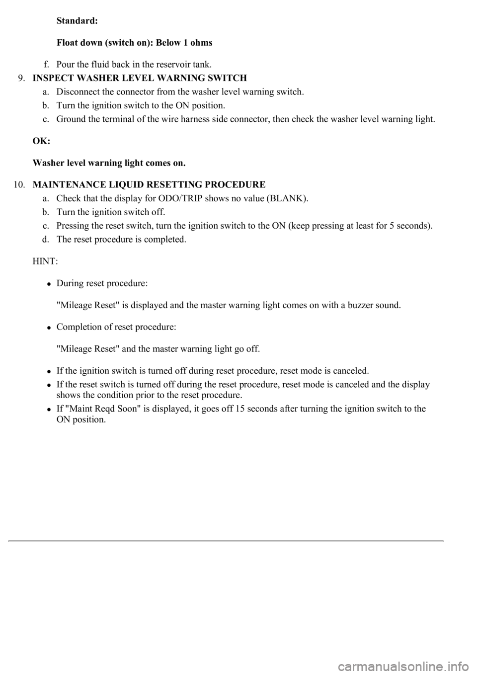
Standard:
Float down (switch on): Below 1 ohms
f. Pour the fluid back in the reservoir tank.
9.INSPECT WASHER LEVEL WARNING SWITCH
a. Disconnect the connector from the washer level warning switch.
b. Turn the ignition switch to the ON position.
c. Ground the terminal of the wire harness side connector, then check the washer level warning light.
OK:
Washer level warning light comes on.
10.MAINTENANCE LIQUID RESETTING PROCEDURE
a. Check that the display for ODO/TRIP shows no value (BLANK).
b. Turn the ignition switch off.
c. Pressing the reset switch, turn the ignition switch to the ON (keep pressing at least for 5 seconds).
d. The reset procedure is completed.
HINT:
During reset procedure:
"Mileage Reset" is displayed and the master warning light comes on with a buzzer sound.
Completion of reset procedure:
"Mileage Reset" and the master warning light go off.
If the ignition switch is turned off during reset procedure, reset mode is canceled.
If the reset switch is turned off during the reset procedure, reset mode is canceled and the display
shows the condition prior to the reset procedure.
If "Maint Reqd Soon" is displayed, it goes off 15 seconds after turning the ignition switch to the
ON position.
Page 2631 of 4500
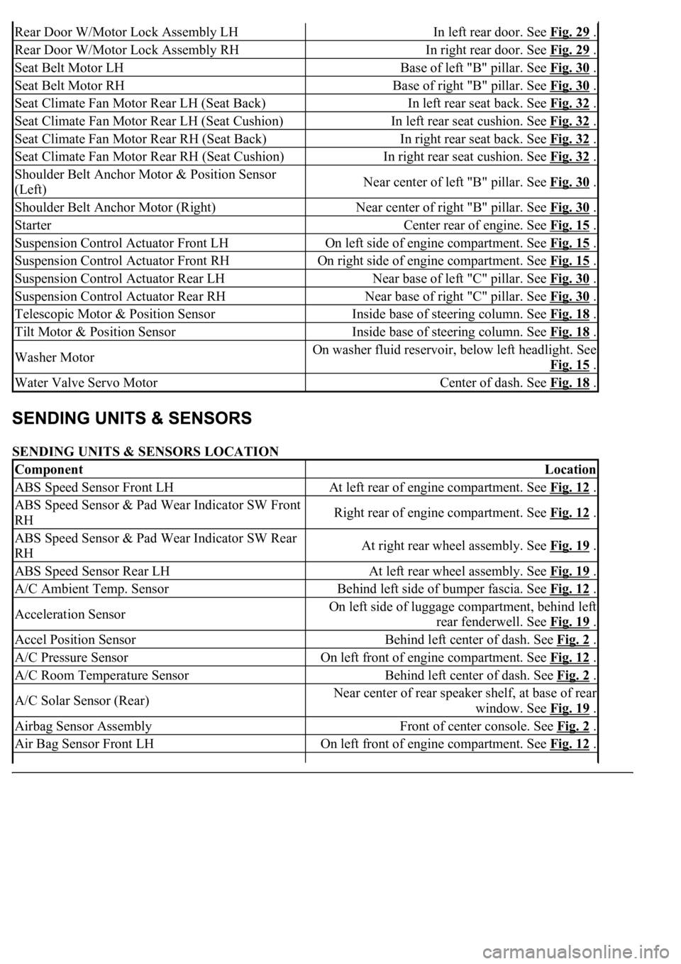
SENDING UNITS & SENSORS LOCATION
Rear Door W/Motor Lock Assembly LHIn left rear door. See Fig. 29 .
Rear Door W/Motor Lock Assembly RHIn right rear door. See Fig. 29 .
Seat Belt Motor LHBase of left "B" pillar. See Fig. 30 .
Seat Belt Motor RHBase of right "B" pillar. See Fig. 30 .
Seat Climate Fan Motor Rear LH (Seat Back)In left rear seat back. See Fig. 32 .
Seat Climate Fan Motor Rear LH (Seat Cushion)In left rear seat cushion. See Fig. 32 .
Seat Climate Fan Motor Rear RH (Seat Back)In right rear seat back. See Fig. 32 .
Seat Climate Fan Motor Rear RH (Seat Cushion)In right rear seat cushion. See Fig. 32 .
Shoulder Belt Anchor Motor & Position Sensor
(Left)Near center of left "B" pillar. See Fig. 30 .
Shoulder Belt Anchor Motor (Right)Near center of right "B" pillar. See Fig. 30 .
StarterCenter rear of engine. See Fig. 15 .
Suspension Control Actuator Front LHOn left side of engine compartment. See Fig. 15 .
Suspension Control Actuator Front RHOn right side of engine compartment. See Fig. 15 .
Suspension Control Actuator Rear LHNear base of left "C" pillar. See Fig. 30 .
Suspension Control Actuator Rear RHNear base of right "C" pillar. See Fig. 30 .
Telescopic Motor & Position SensorInside base of steering column. See Fig. 18 .
Tilt Motor & Position SensorInside base of steering column. See Fig. 18 .
Washer MotorOn washer fluid reservoir, below left headlight. See
Fig. 15
.
Water Valve Servo MotorCenter of dash. See Fig. 18 .
ComponentLocation
ABS Speed Sensor Front LHAt left rear of engine compartment. See Fig. 12 .
ABS Speed Sensor & Pad Wear Indicator SW Front
RHRight rear of engine compartment. See Fig. 12 .
ABS Speed Sensor & Pad Wear Indicator SW Rear
RHAt right rear wheel assembly. See Fig. 19 .
ABS Speed Sensor Rear LHAt left rear wheel assembly. See Fig. 19 .
A/C Ambient Temp. SensorBehind left side of bumper fascia. See Fig. 12 .
Acceleration SensorOn left side of luggage compartment, behind left
rear fenderwell. See Fig. 19
.
Accel Position SensorBehind left center of dash. See Fig. 2 .
A/C Pressure SensorOn left front of engine compartment. See Fig. 12 .
A/C Room Temperature SensorBehind left center of dash. See Fig. 2 .
A/C Solar Sensor (Rear)Near center of rear speaker shelf, at base of rear
window. See Fig. 19
.
Airbag Sensor AssemblyFront of center console. See Fig. 2 .
Air Bag Sensor Front LHOn left front of engine compartment. See Fig. 12 .
Page 2634 of 4500
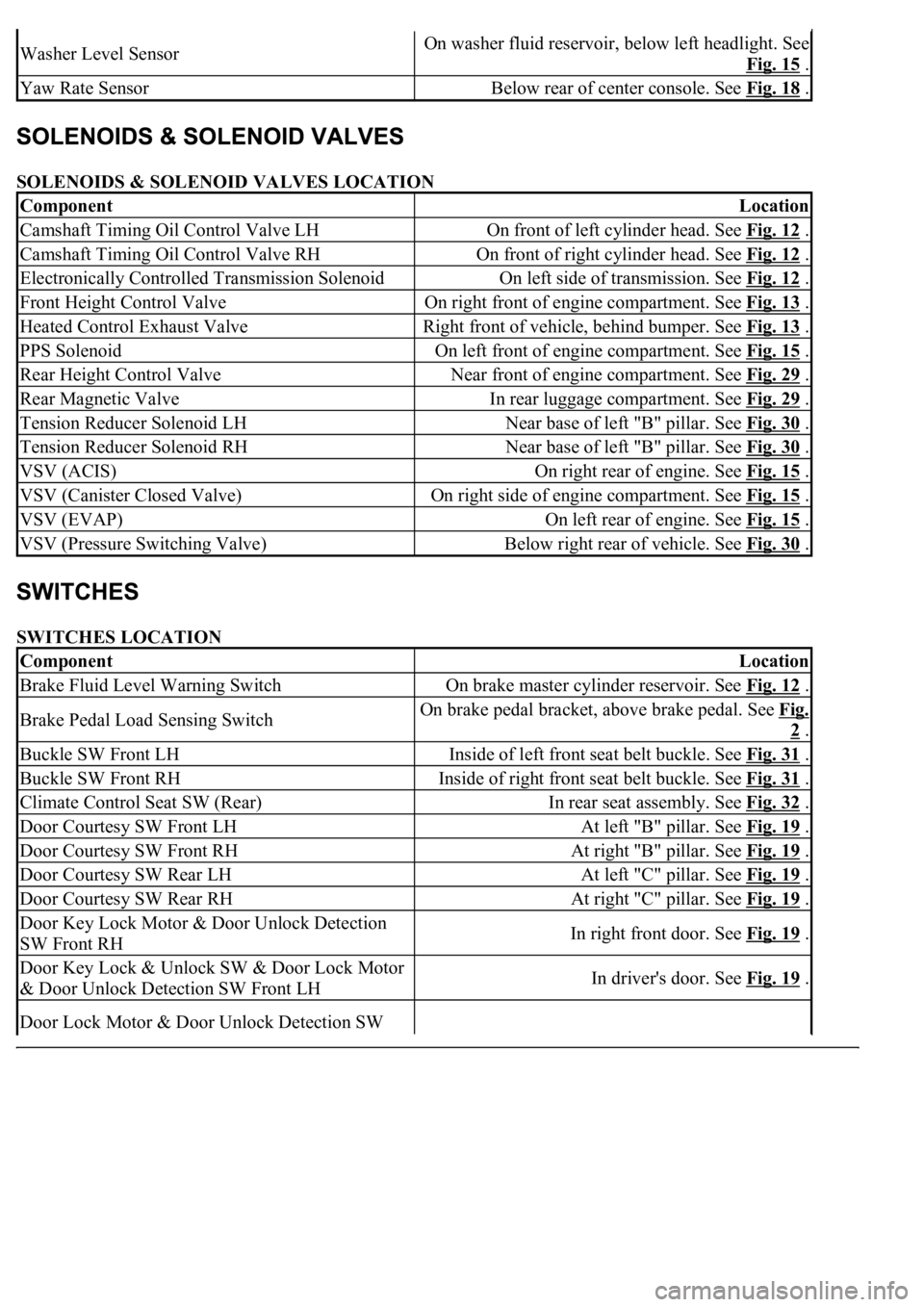
SOLENOIDS & SOLENOID VALVES LOCATION
SWITCHES LOCATION
Washer Level SensorOn washer fluid reservoir, below left headlight. See
Fig. 15
.
Yaw Rate SensorBelow rear of center console. See Fig. 18 .
ComponentLocation
Camshaft Timing Oil Control Valve LHOn front of left cylinder head. See Fig. 12 .
Camshaft Timing Oil Control Valve RHOn front of right cylinder head. See Fig. 12 .
Electronically Controlled Transmission SolenoidOn left side of transmission. See Fig. 12 .
Front Height Control ValveOn right front of engine compartment. See Fig. 13 .
Heated Control Exhaust ValveRight front of vehicle, behind bumper. See Fig. 13 .
PPS SolenoidOn left front of engine compartment. See Fig. 15 .
Rear Height Control ValveNear front of engine compartment. See Fig. 29 .
Rear Magnetic ValveIn rear luggage compartment. See Fig. 29 .
Tension Reducer Solenoid LHNear base of left "B" pillar. See Fig. 30 .
Tension Reducer Solenoid RHNear base of left "B" pillar. See Fig. 30 .
VSV (ACIS)On right rear of engine. See Fig. 15 .
VSV (Canister Closed Valve)On right side of engine compartment. See Fig. 15 .
VSV (EVAP)On left rear of engine. See Fig. 15 .
VSV (Pressure Switching Valve)Below right rear of vehicle. See Fig. 30 .
ComponentLocation
Brake Fluid Level Warning SwitchOn brake master cylinder reservoir. See Fig. 12 .
Brake Pedal Load Sensing SwitchOn brake pedal bracket, above brake pedal. See Fig.
2 .
Buckle SW Front LHInside of left front seat belt buckle. See Fig. 31 .
Buckle SW Front RHInside of right front seat belt buckle. See Fig. 31 .
Climate Control Seat SW (Rear)In rear seat assembly. See Fig. 32 .
Door Courtesy SW Front LHAt left "B" pillar. See Fig. 19 .
Door Courtesy SW Front RHAt right "B" pillar. See Fig. 19 .
Door Courtesy SW Rear LHAt left "C" pillar. See Fig. 19 .
Door Courtesy SW Rear RHAt right "C" pillar. See Fig. 19 .
Door Key Lock Motor & Door Unlock Detection
SW Front RHIn right front door. See Fig. 19 .
Door Key Lock & Unlock SW & Door Lock Motor
& Door Unlock Detection SW Front LHIn driver's door. See Fig. 19 .
Door Lock Motor & Door Unlock Detection SW
Page 3361 of 4500
140.INSTALL ENGINE UNDER COVER NO.2
141.INSTALL ENGINE UNDER COVER NO.1
142.INSTALL FRONT WHEEL
143.INSTALL AIR CLEANER ASSY
144.INSTALL INTAKE AIR CONNECTOR PIPE
145.INSTALL AIR CLEANER INLET NO.1
146.INSTALL V-BANK COVER
147.INSTALL HOOD SUB-ASSY (See ADJUSTMENT
and OVERHAUL )
148.CONNECT BATTERY NEGATIVE TERMINAL
149.ADD AUTOMATIC TRANSMISSION FLUID
150.ADD ENGINE COOLANT (See REPLACEMENT
)
151.ADD ENGINE OIL (See ON
-VEHICLE INSPECTION )
152.ADD POWER STEERING FLUID
153.BLEED POWER STEERING FLUID
154.INSPECT AUTOMATIC TRANSMISSION FLUID (See ADJUSTMENT
)
155.INSPECT ENGINE OIL LEAKS
156.CHECK FOR ENGINE COOLANT LEAKS
157.INSPECT FOR FUEL LEAKS
158.CHECK FOR EXHAUST GAS LEAKS
159.INSPECT AND ADJUST FRONT WHEEL ALIGNMENT
160.INSPECT IGNITION TIMING
161.INSPECT ENGINE IDLE SPEED
162.INSPECT CO/HC
163.ADJUST ENGINE (See INSPECTION
)
164.CHECK ABS SPEED SENSOR SIGNAL (See TEST MODE PROCEDURE
)
OVERHAUL
1.REMOVE SPARK PLUG
2.REMOVE OIL FILLER CAP SUB-ASSY
3.REMOVE CYLINDER HEAD COVER SUB-ASSY LH
a. Remove the 9 bolts, 9 seal washers, cylinder head cover and gasket.
4.REMOVE CYLINDER HEAD COVER SUB-ASSY
a. Remove the 9 bolts, 9 seal washers, c
ylinder head cover and gasket.
Page 3788 of 4500
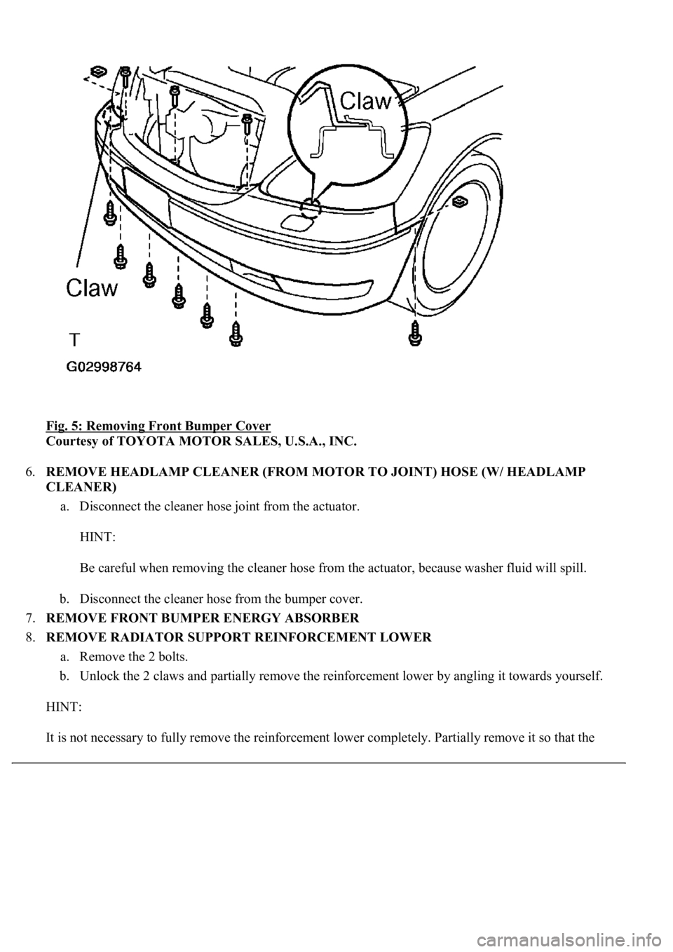
Fig. 5: Removing Front Bumper Cover
Courtesy of TOYOTA MOTOR SALES, U.S.A., INC.
6.REMOVE HEADLAMP CLEANER (FROM MOTOR TO JOINT) HOSE (W/ HEADLAMP
CLEANER)
a. Disconnect the cleaner hose joint from the actuator.
HINT:
Be careful when removing the cleaner hose from the actuator, because washer fluid will spill.
b. Disconnect the cleaner hose from the bumper cover.
7.REMOVE FRONT BUMPER ENERGY ABSORBER
8.REMOVE RADIATOR SUPPORT REINFORCEMENT LOWER
a. Remove the 2 bolts.
b. Unlock the 2 claws and partially remove the reinforcement lower by angling it towards yourself.
HINT:
It is not necessar
y to fully remove the reinforcement lower completely. Partially remove it so that the