Page 12 of 4500

Fig. 8: ABS & TRACTION Actuator - Vehicle Stability Control
Courtesy of TOYOTA MOTOR SALES, U.S.A., INC.
Operation description
The skid control ECU determines vehicle condition by receiving signals from the speed sensor, yaw rate
and deceleration sensor and steering angle sensor. The skid control ECU controls engine torque with the
ECM, vehicle position with suspension control ECU via CAN communication, and oil pressure with the
pump and solenoid valve. The warning light comes on and the buzzer sounds when the system is
operating.
2.ABS with EBD & BA & TRAC & VSC OPERATION
a. Skid control ECU calculates vehicle stability tendency based on the signal of sensors, speed sensor,
yaw rate and deceleration sensor and steering angle sensor. And it judges whether the control of
engine output torque by electronic control throttle and of wheel brake pressure by brake actuator
will operate or not by the calculation results.
b. The SLIP indicator blinks and the VSC buzzer sounds to inform the driver that the VSC system is
operating. The SLIP indicator also blinks when TRAC is operating, and the operation being
performed is displayed.
3.FAIL SAFE FUNCTION
a. When a failure occurs in the ABS with BA & TRAC & VSC systems, the ABS warning light and
the VSC warning light turns on and the ABS with BA & TRAC & VSC operations are prohibited.
In addition to this, when there is a failure that disables the EBD operation, the brake warning light
also comes on and the EBD operation is prohibited (see FAIL
-SAFE CHART ).
b. If some control is prohibited due to a malfunction during it's operation, that control will be cut off
gradually not to change stability of vehicle suddenly.
4.PRE-COLLISION BRAKE ASSIST SYSTEM (w/ PRE-COLLISION BRAKE ASSIST SYSTEM)
Page 27 of 4500
Fig. 19: Identifying VSC Location
Courtesy of TOYOTA MOTOR SALES, U.S.A., INC.
If the indicator remains on, proceed to troubleshooting for the light circuit below.
TROUBLE AREA REFERENCE
2.SENSOR SIGNAL CHECK BY TEST MODE
HINT:
If the ignition switch is turned from ON to the ACC or LOCK position during test mode, DTC of
Trouble areaSee Procedure
ABS warning light circuitABS WARNING LIGHT CIRCUIT (REMAINS ON)
BRAKE warning light circuitBRAKE WARNING LIGHT CIRCUIT
TRAC OFF indicator light
circuitTRAC OFF INDICATOR LIGHT, TRAC OFF SWITCH
CIRCUIT
SLIP indicator light circuitSLIP INDICATOR LIGHT CIRCUIT
Page 28 of 4500
sensor check function will be erased.
<002700580055004c0051004a0003005700480056005700030050005200470048000f00030028002600380003005500480046005200550047005600030044004f004f0003002700370026000300520049000300560048005100560052005500030046004b00
480046004e000300490058005100460057004c005200510011[ By preforming sensor signal
check, the codes are erased if normality is confirmed. The codes left over are the codes where
abnormality was found.
a. PROCEDURES FOR TEST MODE
1. Turn the ignition switch off.
2. Connect the hand-held tester to the DLC3.
3. Check that the steering wheel is in the straight-ahead position and move the shift lever to the
P position.
4. Turn the ignition switch to the ON position.
Fig. 20: Connecting Hand
-Held Tester To DLC3
Courtesy of TOYOTA MOTOR SALES, U.S.A., INC.
Page 39 of 4500

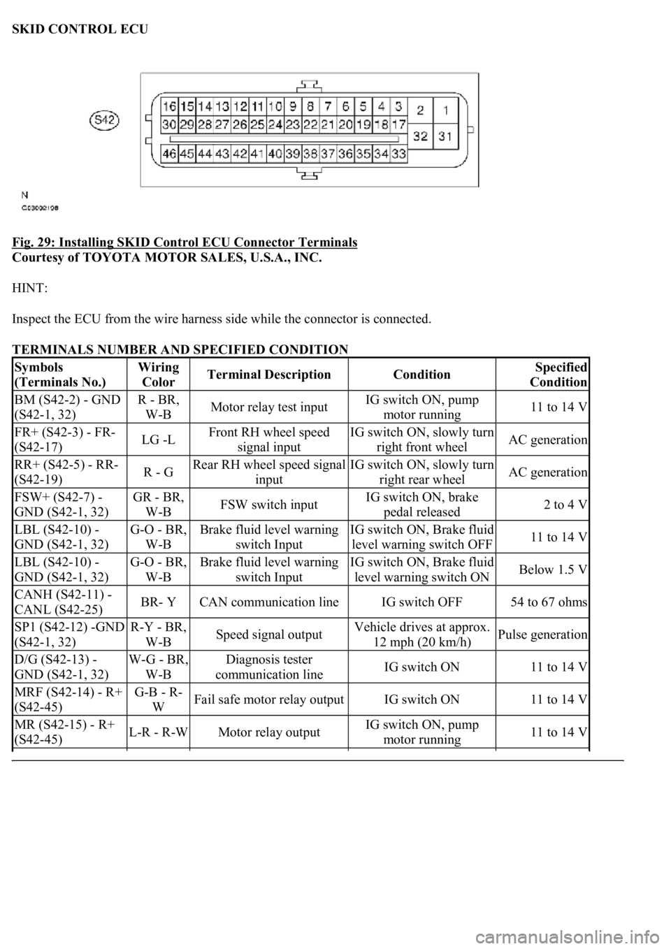
SKID CONTROL ECU
Fig. 29: Installing SKID Control ECU Connector Terminals
Courtesy of TOYOTA MOTOR SALES, U.S.A., INC.
HINT:
Inspect the ECU from the wire harness side while the connector is connected.
TERMINALS NUMBER AND SPECIFIED CONDITION
Symbols
(Terminals No.)Wiring
ColorTerminal DescriptionConditionSpecified
Condition
BM (S42-2) - GND
(S42-1, 32)R - BR,
W-BMotor relay test inputIG switch ON, pump
motor running11 to 14 V
FR+ (S42-3) - FR-
(S42-17)LG -LFront RH wheel speed
signal inputIG switch ON, slowly turn
right front wheelAC generation
RR+ (S42-5) - RR-
(S42-19)R - GRear RH wheel speed signal
inputIG switch ON, slowly turn
right rear wheelAC generation
FSW+ (S42-7) -
GND (S42-1, 32)GR - BR,
W-BFSW switch inputIG switch ON, brake
pedal released2 to 4 V
LBL (S42-10) -
GND (S42-1, 32)G-O - BR,
W-BBrake fluid level warning
switch InputIG switch ON, Brake fluid
level warning switch OFF11 to 14 V
LBL (S42-10) -
GND (S42-1, 32)G-O - BR,
W-BBrake fluid level warning
switch InputIG switch ON, Brake fluid
level warning switch ONBelow 1.5 V
CANH (S42-11) -
CANL (S42-25)BR- YCAN communication lineIG switch OFF54 to 67 ohms
SP1 (S42-12) -GND
(S42-1, 32)R-Y - BR,
W-BSpeed signal outputVehicle drives at approx.
12 mph (20 km/h)Pulse generation
D/G (S42-13) -
GND (S42-1, 32)W-G - BR,
W-BDiagnosis tester
communication lineIG switch ON11 to 14 V
MRF (S42-14) - R+
(S42-45)G-B - R-
WFail safe motor relay outputIG switch ON11 to 14 V
MR (S42-15) - R+
(S42-45)L-R - R-WMotor relay outputIG switch ON, pump
motor running11 to 14 V
Page 40 of 4500

1.DIAGNOSIS
FL+ (S42-18) - FL-
(S42-4)P -VFront LH wheel speed
signal inputIG switch ON, slowly turn
left front wheelAC generation
RL+ (S42-20) - RL-
(S42-6)BR-W -
BRRear LH wheel speed signal
inputIG switch ON, slowly turn
left rear wheelAC generation
TS (S42-24) -GND
(S42-1, 32)B - BR,
W-BSensor check inputIG switch ON11 to 14 V
STP (S42-27) -
GND (S42-1, 32)G-W - BR,
W-BStop lamp switch inputStop light switch ON
(Brake pedal pushed)8 to 14 V
STP (S42-27) -
GND (S42-1, 32)G-W - BR,
W-BStop lamp switch inputStop light switch OFF
(Brake pedal released)Below 1.5 V
PKB (S42-28) -
GND (S42-1, 32)B-L - BR,
W-BParking brake switch inputIG switch ON, parking
brake switch ONBelow 1.5 V
PKB (S42-28) -
GND (S42-1, 32)B-L - BR,
W-BParking brake switch inputIG switch ON, parking
brake switch OFF11 to 14 V
BZ (S42-30) -GND
(S42-1, 32)W-R - BR,
W-BBuzzer outputIG switch ON, VSC
buzzer soundsBelow 1.0 <-->
11 to 14 V
BZ (S42-30) -GND
(S42-1, 32)W-R - BR,
W-BBuzzer outputIG switch ON, VSC
buzzer does not sound11 to 14 V
+BS (S42-31) -
GND (S42-1, 32)B - BR,
W-BSolenoid relay power supplyAlways11 to 14 V
FRO (S42-37) -
GND (S42-1, 32)Y-R - BR,
W-BFront RH wheel speed
signal outputVehicle drives at approx.
12 mph (20 km/h)Pulse generation
FLO (S42-38) -
GND (S42-1, 32)Y-B - BR,
W-BFront LH wheel speed
signal outputVehicle drives at approx.
12 mph (20 km/h)Pulse generation
INIT (S42-41) -
GND (S42-1, 32)GR-R -
BR, W-BThe pressure warning
standardization switch InputIG switch ON, The
pressure warning switch
ON
Below 1.5 V
INIT (S42-41) -
GND (S42-1, 32)GR-R -
BR, W-BThe pressure warning
standardization switch InputIG switch ON, The
pressure warning switch
OFF
11 to 14 V
WFSE (S42-42) -
GND (S42-1, 32)LG-B -
BR, W-BWFSE inputIG switch ON11 to 14 V
CSW (S42-43) -
GND (S42-1, 32)Y-G - BR,
W-BTRAC cut switch InputIG switch ON, TRAC
OFF switch is off11 to 14 V
CSW (S42-43) -
GND (S42-1, 32)Y-G - BR,
W-BTRAC cut switch InputIG switch ON, TRAC
OFF switch is onBelow 1.5 V
R+ (S42-45) -GND
(S42-1, 32)R-W - BR,
W-BPower supply for motor
relayIG switch ON11 to 14 V
IG1 (S42-46) -GND
(S42-1, 32)B-R - BR,
W-BIG1 power supplyIG switch ON11 to 14 V
Page 105 of 4500

HINT:
This DTC is output when the VSC system detects a malfunction in the ABS system.
When DTC C1223/43 is memorized, there is no malfunction in the skid control ECU.
CIRCUIT DESCRIPTION
DTC DETECTING CONDITION DESCRIPTION
INSPECTION PROCEDURE
1.CHECK DTC (FOR ABS SYSTEM)
a. Clear the DTC (see DTC CHECK/CLEAR
).
b. Turn the ignition switch to the ON position.
c. Check that the same DTC is recorded (see DTC CHECK/CLEAR
).
OK: Go to next step
The same DTC is recorded.
NG: PROCEED TO NEXT CIRCUIT INSPECTION SHOWN IN PROBLEM SYMPTOMS
TABLE
HINT:
It is suspect that the DTCs output was caused by the poor connection of the connector terminal.
OK REPAIR CIRCUIT INDICATED BY OUTPUT DTC
CIRCUIT DESCRIPTION
The steering angle sensor signal is sent to the skid control ECU through the CAN communication system. When
there is a malfunction in the communication, it will be detected by the diagnosis function.
DTC No.DTC Detecting ConditionTrouble Area
C1223/43Malfunction in ABS control systemABS control system
Page 120 of 4500
CONDITION DESCRIPTION
B: REPAIR OR REPLACE HARNESS OR CONNECTOR
Fig. 86: Oscilloscope Waveform Signal Description
Courtesy of TOYOTA MOTOR SALES, U.S.A., INC.
A: Go to next step
3.RECONFIRM DTC
a. Clear the DTC.
b. Turn the ignition switch to the ON position.
c. Check that the same DTC is recorded (see DTC CHECK/CLEAR
).
OK: Go to next step
The same DTC is recorded.
NG: REPLACE ABS & TRACTION ACTUATOR ASSY
OKNo ChangeA
NGChangeB
Page 174 of 4500

Fig. 126: Inspecting Pad Wear Indicator Wire Assy
Courtesy of TOYOTA MOTOR SALES, U.S.A., INC.
Standard:
TESTER CONNECTION SPECIFIED CONDITION
REAR:
HINT:
Check that there are no scratches or cracks on the pad wear indicator.
a. Remove the rear wheel RH.
b. Disconnect the pad wear indicator connector.
c. Measure the resistance according to the value (s) in the table below.
Standard:
TESTER CONNECTION SPECIFIED CONDITION
NG: REPLACE PAD WEAR INDICATOR WIRE ASSY
OK: REPLACE ABS & TRACTION ACTUATOR ASSY (SEE REPLACEMENT
)
CIRCUIT DESCRIPTION
The skid control ECU detects the TRAC control main switch ON/OFF signal and turns the TRAC OFF light
on/off.
When the TRAC control switch is pressed, the TRAC control does not operate and the TRAC OFF light comes
on.
The skid control ECU connected to the combination meter via CAN and MPX communications.
Tester ConnectionSpecified Condition
Terminal a - Terminal bBelow 1 ohms
Terminal a - Body ground1 Mohms or higher
Tester ConnectionSpecified Condition
Terminal a - Terminal bBelow 1 ohms
Terminal a - Body ground1 Mohms or higher