2003 LEXUS LS430 turn signal
[x] Cancel search: turn signalPage 1603 of 4500
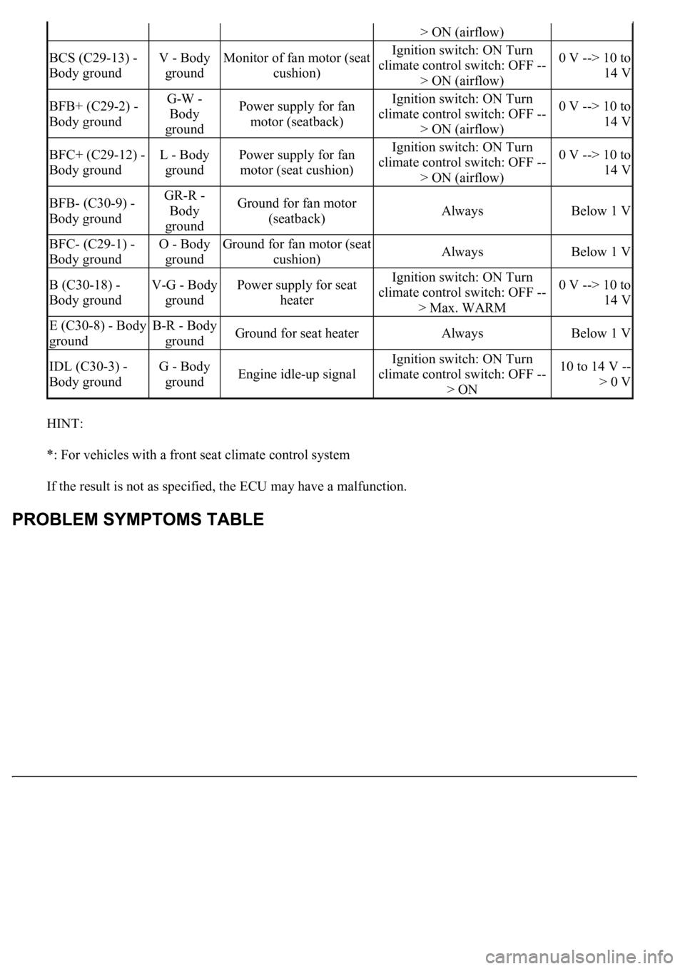
HINT:
*: For vehicles with a front seat climate control system
If the result is not as specified, the ECU may have a malfunction.
> ON (airflow)
BCS (C29-13) -
Body groundV - Body
groundMonitor of fan motor (seat
cushion)Ignition switch: ON Turn
climate control switch: OFF --
> ON (airflow)0 V --> 10 to
14 V
BFB+ (C29-2) -
Body groundG-W -
Body
groundPower supply for fan
motor (seatback)Ignition switch: ON Turn
climate control switch: OFF --
> ON (airflow)0 V --> 10 to
14 V
BFC+ (C29-12) -
Body groundL - Body
groundPower supply for fan
motor (seat cushion)Ignition switch: ON Turn
climate control switch: OFF --
> ON (airflow)0 V --> 10 to
14 V
BFB- (C30-9) -
Body groundGR-R -
Body
groundGround for fan motor
(seatback)AlwaysBelow 1 V
BFC- (C29-1) -
Body groundO - Body
groundGround for fan motor (seat
cushion)AlwaysBelow 1 V
B (C30-18) -
Body groundV-G - Body
groundPower supply for seat
heaterIgnition switch: ON Turn
climate control switch: OFF --
> Max. WARM0 V --> 10 to
14 V
E (C30-8) - Body
groundB-R - Body
groundGround for seat heaterAlwaysBelow 1 V
IDL (C30-3) -
Body groundG - Body
groundEngine idle-up signal
Ignition switch: ON Turn
climate control switch: OFF --
> ON10 to 14 V --
> 0 V
Page 1605 of 4500
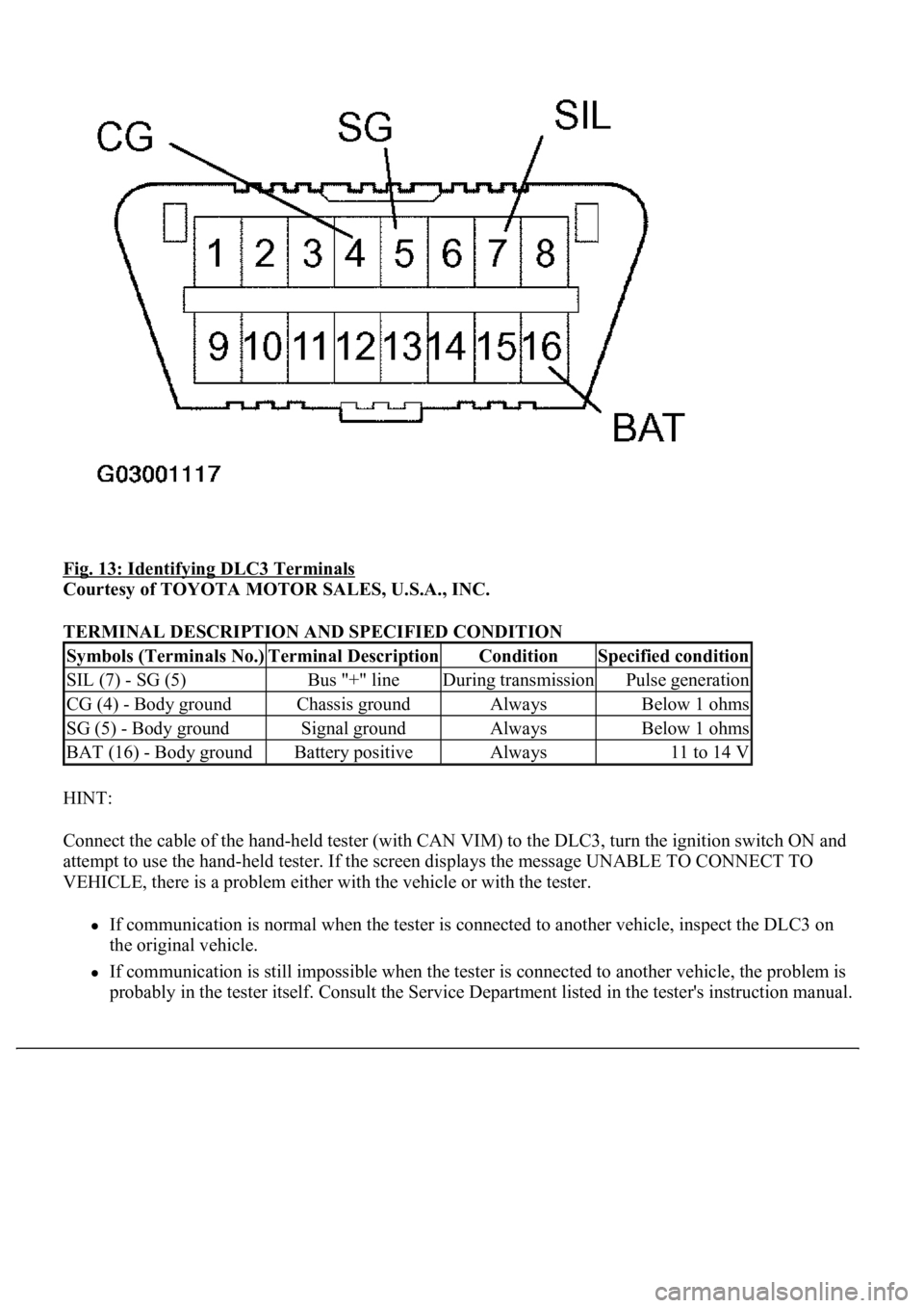
Fig. 13: Identifying DLC3 Terminals
Courtesy of TOYOTA MOTOR SALES, U.S.A., INC.
TERMINAL DESCRIPTION AND SPECIFIED CONDITION
HINT:
Connect the cable of the hand-held tester (with CAN VIM) to the DLC3, turn the ignition switch ON and
attempt to use the hand-held tester. If the screen displays the message UNABLE TO CONNECT TO
VEHICLE, there is a problem either with the vehicle or with the tester.
If communication is normal when the tester is connected to another vehicle, inspect the DLC3 on
the original vehicle.
If communication is still impossible when the tester is connected to another vehicle, the problem is
probably in the tester itself. Consult the Service Department listed in the tester's instruction manual.
Symbols (Terminals No.)Terminal DescriptionConditionSpecified condition
SIL (7) - SG (5)Bus "+" lineDuring transmissionPulse generation
CG (4) - Body groundChassis groundAlwaysBelow 1 ohms
SG (5) - Body groundSignal groundAlwaysBelow 1 ohms
BAT (16) - Body groundBattery positiveAlways11 to 14 V
Page 1744 of 4500
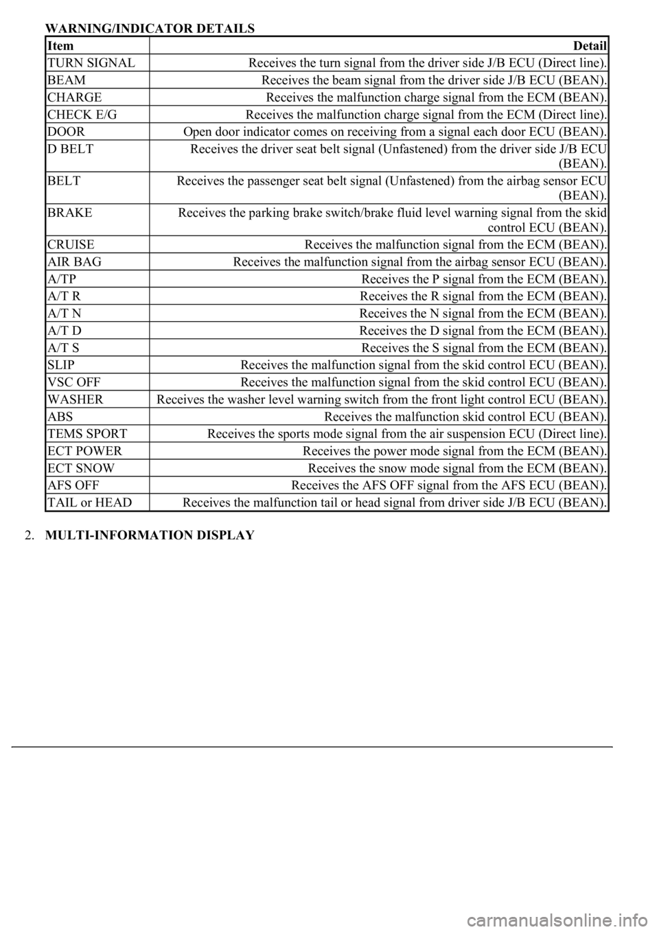
WARNING/INDICATOR DETAILS
2.MULTI-INFORMATION DISPLAY
ItemDetail
TURN SIGNALReceives the turn signal from the driver side J/B ECU (Direct line).
BEAMReceives the beam signal from the driver side J/B ECU (BEAN).
CHARGEReceives the malfunction charge signal from the ECM (BEAN).
CHECK E/GReceives the malfunction charge signal from the ECM (Direct line).
DOOROpen door indicator comes on receiving from a signal each door ECU (BEAN).
D BELTReceives the driver seat belt signal (Unfastened) from the driver side J/B ECU
(BEAN).
BELTReceives the passenger seat belt signal (Unfastened) from the airbag sensor ECU
(BEAN).
BRAKEReceives the parking brake switch/brake fluid level warning signal from the skid
control ECU (BEAN).
CRUISEReceives the malfunction signal from the ECM (BEAN).
AIR BAGReceives the malfunction signal from the airbag sensor ECU (BEAN).
A/TPReceives the P signal from the ECM (BEAN).
A/T RReceives the R signal from the ECM (BEAN).
A/T NReceives the N signal from the ECM (BEAN).
A/T DReceives the D signal from the ECM (BEAN).
A/T SReceives the S signal from the ECM (BEAN).
SLIPReceives the malfunction signal from the skid control ECU (BEAN).
VSC OFFReceives the malfunction signal from the skid control ECU (BEAN).
WASHERReceives the washer level warning switch from the front light control ECU (BEAN).
ABSReceives the malfunction skid control ECU (BEAN).
TEMS SPORTReceives the sports mode signal from the air suspension ECU (Direct line).
ECT POWERReceives the power mode signal from the ECM (BEAN).
ECT SNOWReceives the snow mode signal from the ECM (BEAN).
AFS OFFReceives the AFS OFF signal from the AFS ECU (BEAN).
TAIL or HEADReceives the malfunction tail or head signal from driver side J/B ECU (BEAN).
Page 1749 of 4500
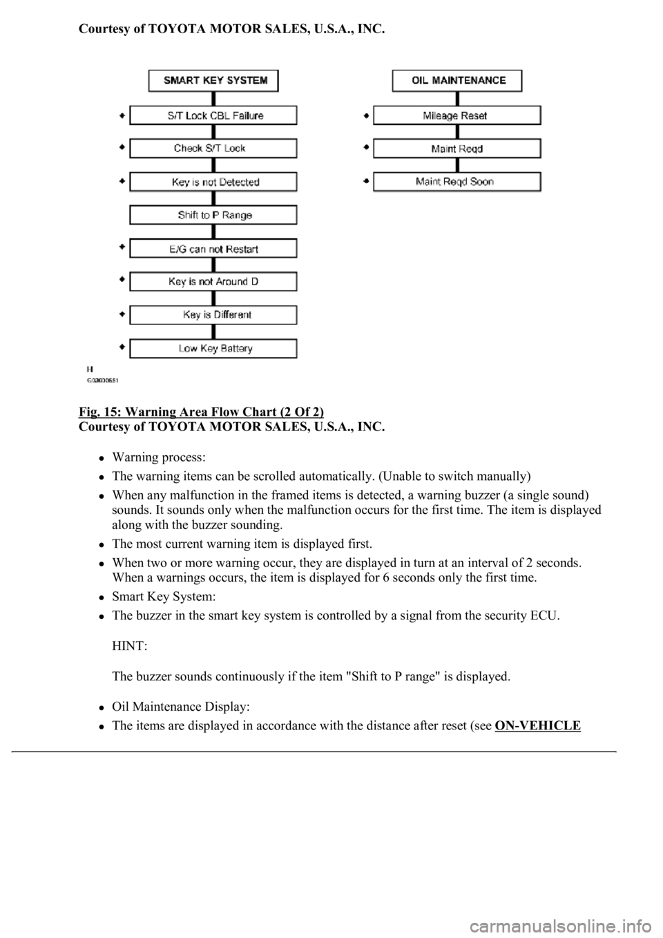
Courtesy of TOYOTA MOTOR SALES, U.S.A., INC.
Fig. 15: Warning Area Flow Chart (2 Of 2)
Courtesy of TOYOTA MOTOR SALES, U.S.A., INC.
Warning process:
The warning items can be scrolled automatically. (Unable to switch manually)
When any malfunction in the framed items is detected, a warning buzzer (a single sound)
sounds. It sounds only when the malfunction occurs for the first time. The item is displayed
along with the buzzer sounding.
The most current warning item is displayed first.
When two or more warning occur, they are displayed in turn at an interval of 2 seconds.
When a warnings occurs, the item is displayed for 6 seconds only the first time.
Smart Key System:
The buzzer in the smart key system is controlled by a signal from the security ECU.
HINT:
The buzzer sounds continuously if the item "Shift to P range" is displayed.
Oil Maintenance Display:
The items are displayed in accordance with the distance after reset (see ON-VEHICLE
Page 1763 of 4500
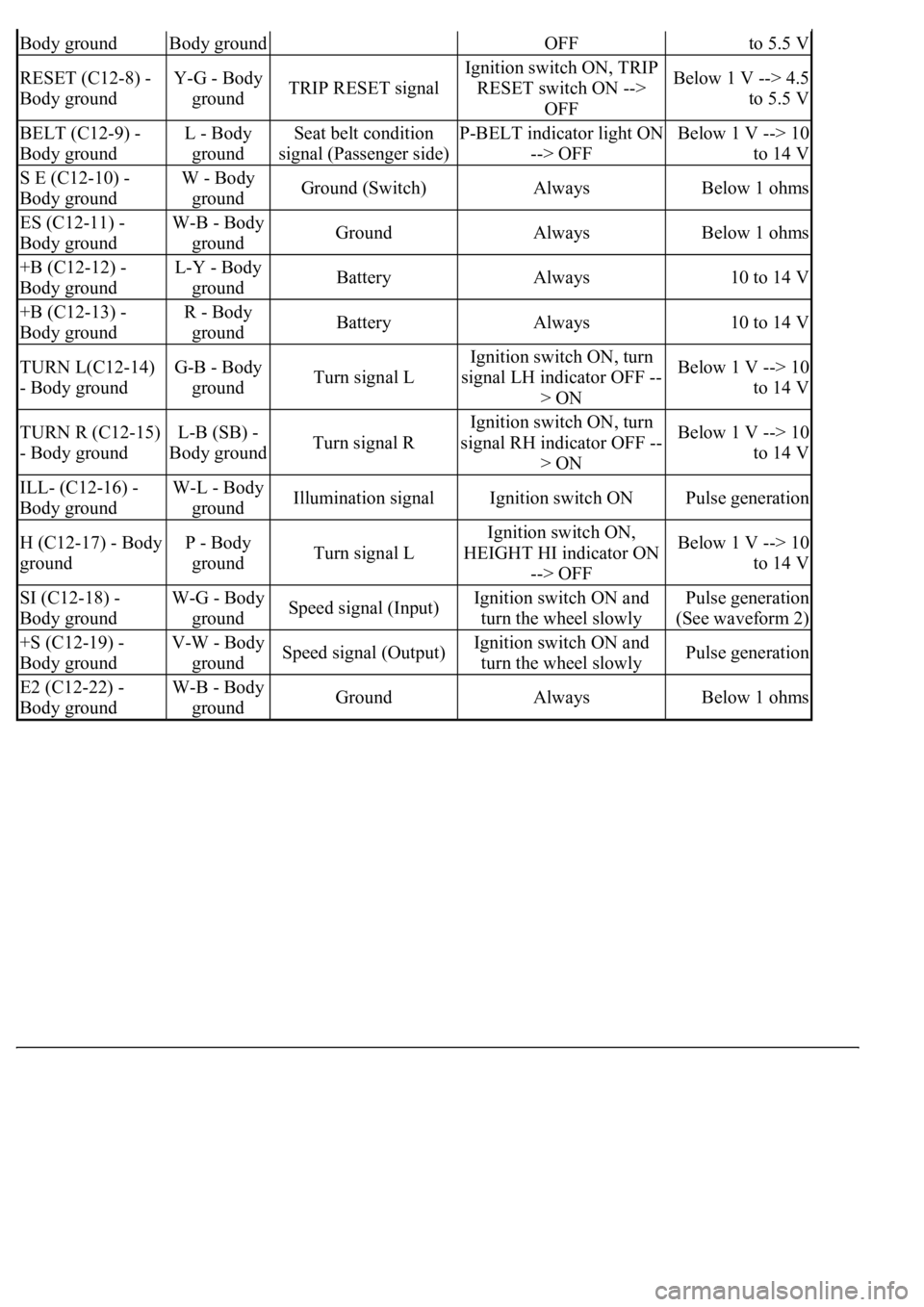
Body groundBody groundOFFto 5.5 V
RESET (C12-8) -
Body groundY-G - Body
groundTRIP RESET signal
Ignition switch ON, TRIP
RESET switch ON -->
OFFBelow 1 V --> 4.5
to 5.5 V
BELT (C12-9) -
Body groundL - Body
groundSeat belt condition
signal (Passenger side)P-BELT indicator light ON
--> OFFBelow 1 V --> 10
to 14 V
S E (C12-10) -
Body groundW - Body
groundGround (Switch)AlwaysBelow 1 ohms
ES (C12-11) -
Body groundW-B - Body
groundGroundAlwaysBelow 1 ohms
+B (C12-12) -
Body groundL-Y - Body
groundBatteryAlways10 to 14 V
+B (C12-13) -
Body groundR - Body
groundBatteryAlways10 to 14 V
TURN L(C12-14)
- Body groundG-B - Body
groundTurn signal L
Ignition switch ON, turn
signal LH indicator OFF --
> ONBelow 1 V --> 10
to 14 V
TURN R (C12-15)
- Body groundL-B (SB) -
Body groundTurn signal R
Ignition switch ON, turn
signal RH indicator OFF --
> ONBelow 1 V --> 10
to 14 V
ILL- (C12-16) -
Body groundW-L - Body
groundIllumination signalIgnition switch ONPulse generation
H (C12-17) - Body
groundP - Body
groundTurn signal L
Ignition switch ON,
HEIGHT HI indicator ON
--> OFFBelow 1 V --> 10
to 14 V
SI (C12-18) -
Body groundW-G - Body
groundSpeed signal (Input)Ignition switch ON and
turn the wheel slowlyPulse generation
(See waveform 2)
+S (C12-19) -
Body groundV-W - Body
groundSpeed signal (Output)Ignition switch ON and
turn the wheel slowlyPulse generation
E2 (C12-22) -
Body groundW-B - Body
groundGroundAlwaysBelow 1 ohms
Page 1774 of 4500
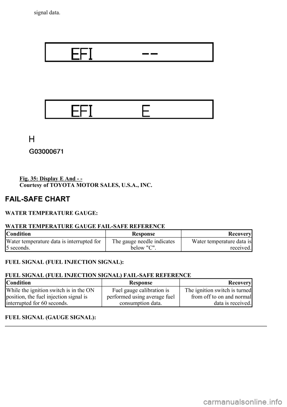
signal data.
Fig. 35: Display E And
- -
Courtesy of TOYOTA MOTOR SALES, U.S.A., INC.
WATER TEMPERATURE GAUGE:
WATER TEMPERATURE GAUGE FAIL-SAFE REFERENCE
FUEL SIGNAL (FUEL INJECTION SIGNAL):
FUEL SIGNAL (FUEL INJECTION SIGNAL) FAIL-SAFE REFERENCE
FUEL SIGNAL (GAUGE SIGNAL):
ConditionResponseRecovery
Water temperature data is interrupted for
5 seconds.The gauge needle indicates
below "C".Water temperature data is
received.
ConditionResponseRecovery
While the ignition switch is in the ON
position, the fuel injection signal is
interrupted for 60 seconds.Fuel gauge calibration is
performed using average fuel
consumption data.The ignition switch is turned
from off to on and normal
data is received.
Page 1775 of 4500
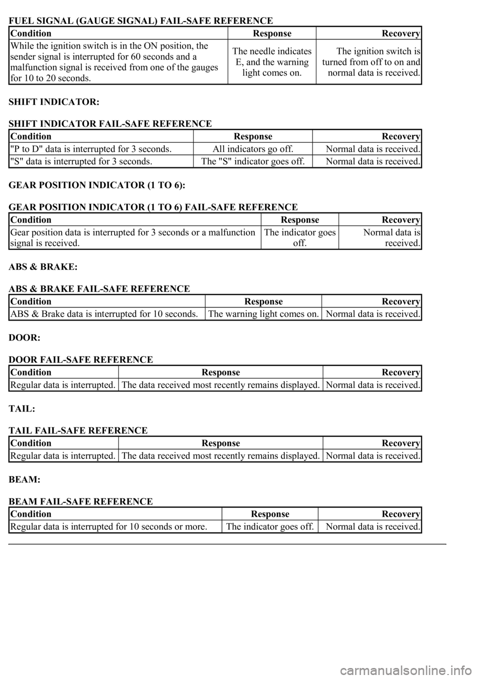
FUEL SIGNAL (GAUGE SIGNAL) FAIL-SAFE REFERENCE
SHIFT INDICATOR:
SHIFT INDICATOR FAIL-SAFE REFERENCE
GEAR POSITION INDICATOR (1 TO 6):
GEAR POSITION INDICATOR (1 TO 6) FAIL-SAFE REFERENCE
ABS & BRAKE:
ABS & BRAKE FAIL-SAFE REFERENCE
DOOR:
DOOR FAIL-SAFE REFERENCE
TAIL:
TAIL FAIL-SAFE REFERENCE
BEAM:
BEAM FAIL-SAFE REFERENCE
ConditionResponseRecovery
While the ignition switch is in the ON position, the
sender signal is interrupted for 60 seconds and a
malfunction signal is received from one of the gauges
for 10 to 20 seconds.The needle indicates
E, and the warning
light comes on.The ignition switch is
turned from off to on and
normal data is received.
ConditionResponseRecovery
"P to D" data is interrupted for 3 seconds.All indicators go off.Normal data is received.
"S" data is interrupted for 3 seconds.The "S" indicator goes off.Normal data is received.
ConditionResponseRecovery
Gear position data is interrupted for 3 seconds or a malfunction
signal is received.The indicator goes
off.Normal data is
received.
ConditionResponseRecovery
ABS & Brake data is interrupted for 10 seconds.The warning light comes on.Normal data is received.
ConditionResponseRecovery
Regular data is interrupted.The data received most recently remains displayed.Normal data is received.
ConditionResponseRecovery
Regular data is interrupted.The data received most recently remains displayed.Normal data is received.
ConditionResponseRecovery
<00350048004a0058004f00440055000300470044005700440003004c00560003004c00510057004800550055005800530057004800470003004900520055000300140013000300560048004600520051004700560003005200550003005000520055004800
11[The indicator goes off.Normal data is received.
Page 1904 of 4500
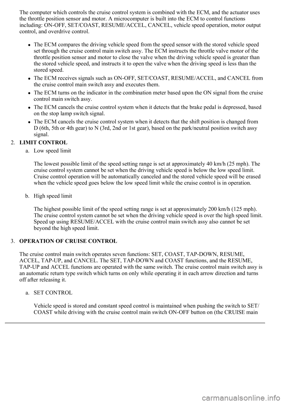
The computer which controls the cruise control system is combined with the ECM, and the actuator uses
the throttle position sensor and motor. A microcomputer is built into the ECM to control functions
including: ON-OFF, SET/COAST, RESUME/ACCEL, CANCEL, vehicle speed operation, motor output
control, and overdrive control.
The ECM compares the driving vehicle speed from the speed sensor with the stored vehicle speed
set through the cruise control main switch assy. The ECM instructs the throttle valve motor of the
throttle position sensor and motor to close the valve when the driving vehicle speed is greater than
the stored vehicle speed, and instructs it to open the valve when the driving speed is less than the
stored speed.
The ECM receives signals such as ON-OFF, SET/COAST, RESUME/ACCEL, and CANCEL from
the cruise control main switch assy and executes them.
The ECM turns on the indicator in the combination meter based upon the ON signal from the cruise
control main switch assy.
The ECM cancels the cruise control system when it detects that the brake pedal is depressed, based
on the stop lamp switch signal.
The ECM cancels the cruise control system when it detects that the shift position is changed from
D (6th, 5th or 4th gear) to N (3rd, 2nd or 1st gear), based on the park/neutral position switch assy
signal.
2.LIMIT CONTROL
a. Low speed limit
The lowest possible limit of the speed setting range is set at approximately 40 km/h (25 mph). The
cruise control system cannot be set when the driving vehicle speed is below the low speed limit.
Cruise control operation will be automatically canceled and the stored vehicle speed will be erased
when the vehicle speed goes below the low speed limit while the cruise control is in operation.
b. High speed limit
The highest possible limit of the speed setting range is set at approximately 200 km/h (125 mph).
The cruise control system cannot be set when the driving vehicle speed is over the high speed limit.
Speed up using RESUME/ACCEL with the cruise control main switch assy also cannot be set
beyond the high speed limit.
3.OPERATION OF CRUISE CONTROL
The cruise control main switch operates seven functions: SET, COAST, TAP-DOWN, RESUME,
ACCEL, TAP-UP, and CANCEL. The SET, TAP-DOWN and COAST functions, and the RESUME,
TAP-UP and ACCEL functions are operated with the same switch. The cruise control main switch assy is
an automatic return type switch which turns on only while operating it in each arrow direction and turns
off after releasing it.
a. SET CONTROL
Vehicle speed is stored and constant speed control is maintained when pushing the switch to SET/
COAST while drivin
g with the cruise control main switch ON-OFF button on (the CRUISE main