2003 LEXUS LS430 turn signal
[x] Cancel search: turn signalPage 1996 of 4500
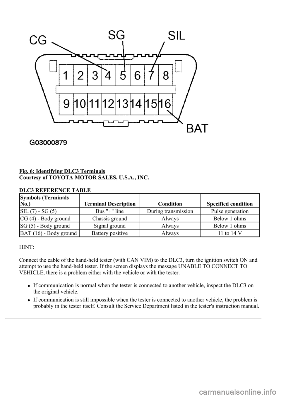
Fig. 6: Identifying DLC3 Terminals
Courtesy of TOYOTA MOTOR SALES, U.S.A., INC.
DLC3 REFERENCE TABLE
HINT:
Connect the cable of the hand-held tester (with CAN VIM) to the DLC3, turn the ignition switch ON and
attempt to use the hand-held tester. If the screen displays the message UNABLE TO CONNECT TO
VEHICLE, there is a problem either with the vehicle or with the tester.
If communication is normal when the tester is connected to another vehicle, inspect the DLC3 on
the original vehicle.
If communication is still impossible when the tester is connected to another vehicle, the problem is
probabl
y in the tester itself. Consult the Service Department listed in the tester's instruction manual.
Symbols (Terminals
No.)
Terminal DescriptionConditionSpecified condition
SIL (7) - SG (5)Bus "+" lineDuring transmissionPulse generation
CG (4) - Body groundChassis groundAlwaysBelow 1 ohms
SG (5) - Body groundSignal groundAlwaysBelow 1 ohms
BAT (16) - Body groundBattery positiveAlways11 to 14 V
Page 1998 of 4500
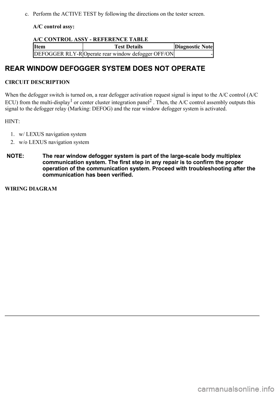
c. Perform the ACTIVE TEST by following the directions on the tester screen.
A/C control assy:
A/C CONTROL ASSY - REFERENCE TABLE
CIRCUIT DESCRIPTION
When the defogger switch is turned on, a rear defogger activation request signal is input to the A/C control (A/C
ECU) from the multi-display
1 or center cluster integration panel2 . Then, the A/C control assembly outputs this
signal to the defogger relay (Marking: DEFOG) and the rear window defogger system is activated.
HINT:
1. w/ LEXUS navigation system
2. w/o LEXUS navigation system
WIRING DIAGRAM
ItemTest DetailsDiagnostic Note
DEFOGGER RLY-ROperate rear window defogger OFF/ON-
Page 2196 of 4500
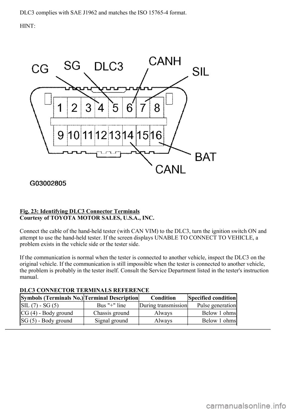
DLC3 complies with SAE J1962 and matches the ISO 15765-4 format.
HINT:
Fig. 23: Identifying DLC3 Connector Terminals
Courtesy of TOYOTA MOTOR SALES, U.S.A., INC.
Connect the cable of the hand-held tester (with CAN VIM) to the DLC3, turn the ignition switch ON and
attempt to use the hand-held tester. If the screen displays UNABLE TO CONNECT TO VEHICLE, a
problem exists in the vehicle side or the tester side.
If the communication is normal when the tester is connected to another vehicle, inspect the DLC3 on the
original vehicle. If the communication is still impossible when the tester is connected to another vehicle,
the problem is probably in the tester itself. Consult the Service Department listed in the tester's instruction
manual.
DLC3 CONNECTOR TERMINALS REFERENCE
Symbols (Terminals No.)Terminal DescriptionConditionSpecified condition
SIL (7) - SG (5)Bus "+" lineDuring transmissionPulse generation
CG (4) - Body groundChassis groundAlwaysBelow 1 ohms
SG (5) - Body groundSignal groundAlwaysBelow 1 ohms
Page 2198 of 4500
Courtesy of TOYOTA MOTOR SALES, U.S.A., INC.
2.CLEAR DTC
a. Connect the hand-held tester to the Controller Area Network Vehicle Interface Module (CAN
VIM). Then connect the CAN VIM to the DLC3.
b. Turn the ignition switch ON.
c. Erase the DTCs by following the prompts on the tester screen.
HINT:
Refer to the hand-held tester operator's manual for further details.
1.DATA LIST
HINT:
Using the hand-held tester's DATA LIST allows switch, sensor, actuator and other item values to be read
without removing any parts. Reading the DATA LIST early in troubleshooting is one way to save time.
1. Connect the hand-held tester (with CAN VIM) to the DLC3.
2. Turn the ignition switch ON.
3. Read the DATA LIST on the tester's screen.
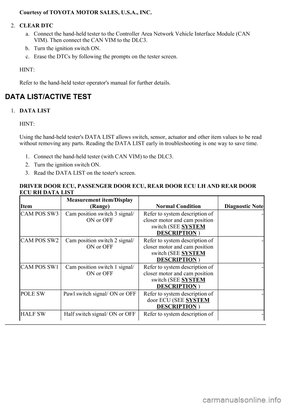
DRIVER DOOR ECU, PASSENGER DOOR ECU, REAR DOOR ECU LH AND REAR DOOR
ECU RH DATA LIST
Item
Measurement item/Display
(Range)
Normal ConditionDiagnostic Note
CAM POS SW3Cam position switch 3 signal/
ON or OFFRefer to system description of
closer motor and cam position
switch (SEE SYSTEM
DESCRIPTION )
-
CAM POS SW2Cam position switch 2 signal/
ON or OFFRefer to system description of
closer motor and cam position
switch (SEE SYSTEM
DESCRIPTION )
-
CAM POS SW1Cam position switch 1 signal/
ON or OFFRefer to system description of
closer motor and cam position
switch (SEE SYSTEM
DESCRIPTION )
-
POLE SWPawl switch signal/ ON or OFFRefer to system description of
door ECU (SEE SYSTEM
DESCRIPTION )
-
HALF SWHalf switch signal/ ON or OFFRefer to system description of -
Page 2433 of 4500
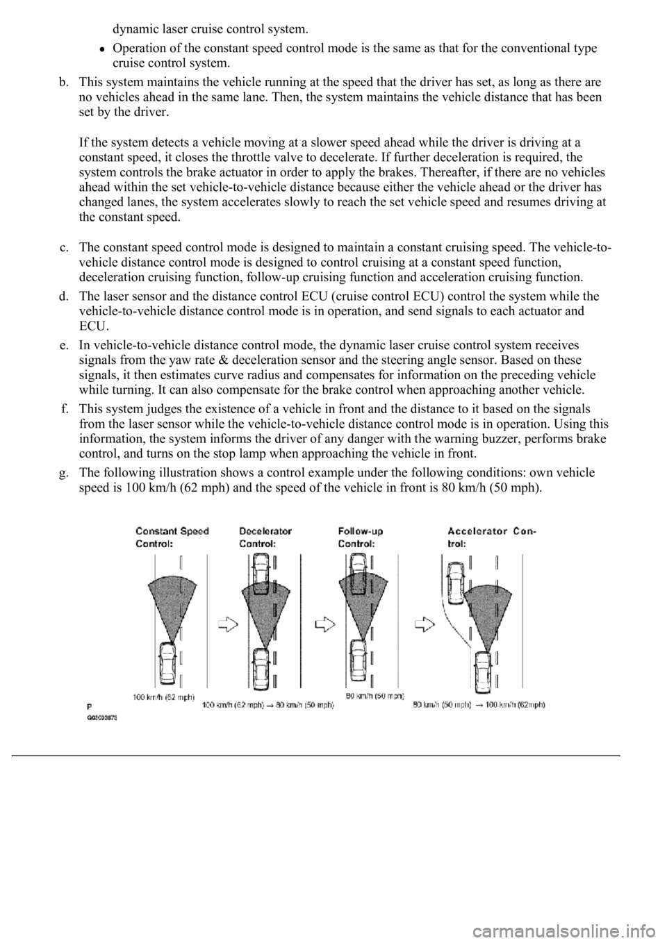
dynamic laser cruise control system.
Operation of the constant speed control mode is the same as that for the conventional type
cruise control system.
b. This system maintains the vehicle running at the speed that the driver has set, as long as there are
no vehicles ahead in the same lane. Then, the system maintains the vehicle distance that has been
set by the driver.
If the system detects a vehicle moving at a slower speed ahead while the driver is driving at a
constant speed, it closes the throttle valve to decelerate. If further deceleration is required, the
system controls the brake actuator in order to apply the brakes. Thereafter, if there are no vehicles
ahead within the set vehicle-to-vehicle distance because either the vehicle ahead or the driver has
changed lanes, the system accelerates slowly to reach the set vehicle speed and resumes driving at
the constant speed.
c. The constant speed control mode is designed to maintain a constant cruising speed. The vehicle-to-
vehicle distance control mode is designed to control cruising at a constant speed function,
deceleration cruising function, follow-up cruising function and acceleration cruising function.
d. The laser sensor and the distance control ECU (cruise control ECU) control the system while the
vehicle-to-vehicle distance control mode is in operation, and send signals to each actuator and
ECU.
e. In vehicle-to-vehicle distance control mode, the dynamic laser cruise control system receives
signals from the yaw rate & deceleration sensor and the steering angle sensor. Based on these
signals, it then estimates curve radius and compensates for information on the preceding vehicle
while turning. It can also compensate for the brake control when approaching another vehicle.
f. This system judges the existence of a vehicle in front and the distance to it based on the signals
from the laser sensor while the vehicle-to-vehicle distance control mode is in operation. Using this
information, the system informs the driver of any danger with the warning buzzer, performs brake
control, and turns on the stop lamp when approaching the vehicle in front.
g. The following illustration shows a control example under the following conditions: own vehicle
speed is 100 km/h (62 mph) and the speed of the vehicle in front is 80 km/h (50 mph).
Page 2438 of 4500
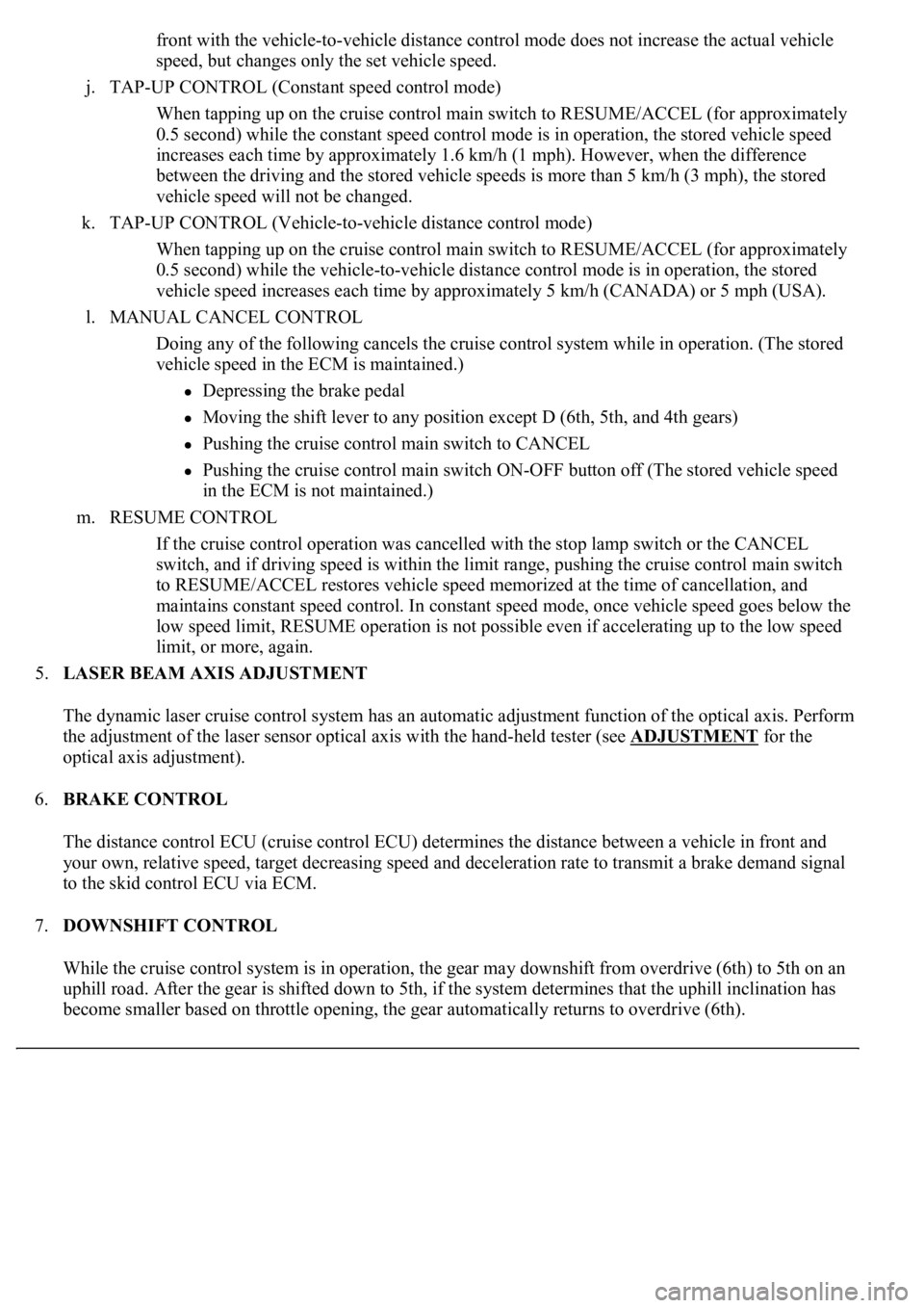
front with the vehicle-to-vehicle distance control mode does not increase the actual vehicle
speed, but changes only the set vehicle speed.
j. TAP-UP CONTROL (Constant speed control mode)
When tapping up on the cruise control main switch to RESUME/ACCEL (for approximately
0.5 second) while the constant speed control mode is in operation, the stored vehicle speed
increases each time by approximately 1.6 km/h (1 mph). However, when the difference
between the driving and the stored vehicle speeds is more than 5 km/h (3 mph), the stored
vehicle speed will not be changed.
k. TAP-UP CONTROL (Vehicle-to-vehicle distance control mode)
When tapping up on the cruise control main switch to RESUME/ACCEL (for approximately
0.5 second) while the vehicle-to-vehicle distance control mode is in operation, the stored
vehicle speed increases each time by approximately 5 km/h (CANADA) or 5 mph (USA).
l. MANUAL CANCEL CONTROL
<00270052004c0051004a000300440051005c00030052004900030057004b0048000300490052004f004f0052005a004c0051004a000300460044005100460048004f005600030057004b00480003004600550058004c005600480003004600520051005700
550052004f00030056005c00560057004800500003005a004b[ile in operation. (The stored
vehicle speed in the ECM is maintained.)
Depressing the brake pedal
<003000520059004c0051004a00030057004b004800030056004b004c004900570003004f0048005900480055000300570052000300440051005c0003005300520056004c0057004c0052005100030048005b0046004800530057000300270003000b001900
57004b000f000300180057004b000f00030044005100470003[4th gears)
Pushing the cruise control main switch to CANCEL
Pushing the cruise control main switch ON-OFF button off (The stored vehicle speed
in the ECM is not maintained.)
m. RESUME CONTROL
If the cruise control operation was cancelled with the stop lamp switch or the CANCEL
switch, and if driving speed is within the limit range, pushing the cruise control main switch
to RESUME/ACCEL restores vehicle speed memorized at the time of cancellation, and
maintains constant speed control. In constant speed mode, once vehicle speed goes below the
low speed limit, RESUME operation is not possible even if accelerating up to the low speed
limit, or more, again.
5.LASER BEAM AXIS ADJUSTMENT
The dynamic laser cruise control system has an automatic adjustment function of the optical axis. Perform
the adjustment of the laser sensor optical axis with the hand-held tester (see ADJUSTMENT
for the
optical axis adjustment).
6.BRAKE CONTROL
The distance control ECU (cruise control ECU) determines the distance between a vehicle in front and
your own, relative speed, target decreasing speed and deceleration rate to transmit a brake demand signal
to the skid control ECU via ECM.
7.DOWNSHIFT CONTROL
While the cruise control system is in operation, the gear may downshift from overdrive (6th) to 5th on an
uphill road. After the gear is shifted down to 5th, if the system determines that the uphill inclination has
become smaller based on throttle opening, the gear automatically returns to overdrive (6th).
Page 2446 of 4500
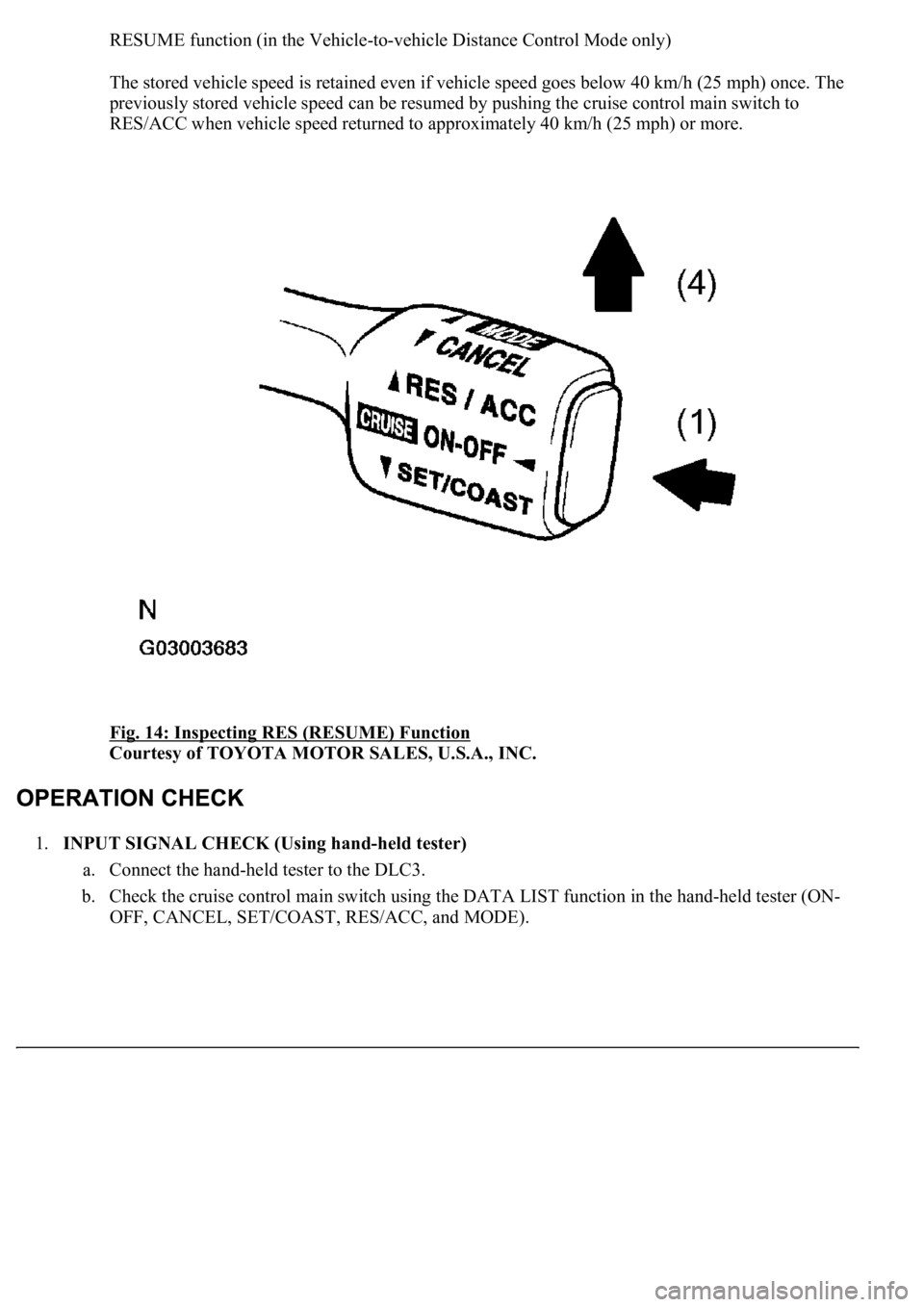
RESUME function (in the Vehicle-to-vehicle Distance Control Mode only)
The stored vehicle speed is retained even if vehicle speed goes below 40 km/h (25 mph) once. The
previously stored vehicle speed can be resumed by pushing the cruise control main switch to
RES/ACC when vehicle speed returned to approximately 40 km/h (25 mph) or more.
Fig. 14: Inspecting RES (RESUME) Function
Courtesy of TOYOTA MOTOR SALES, U.S.A., INC.
1.INPUT SIGNAL CHECK (Using hand-held tester)
a. Connect the hand-held tester to the DLC3.
b. Check the cruise control main switch using the DATA LIST function in the hand-held tester (ON-
OFF, CANCEL, SET/COAST, RES/ACC, and MODE).
Page 2467 of 4500
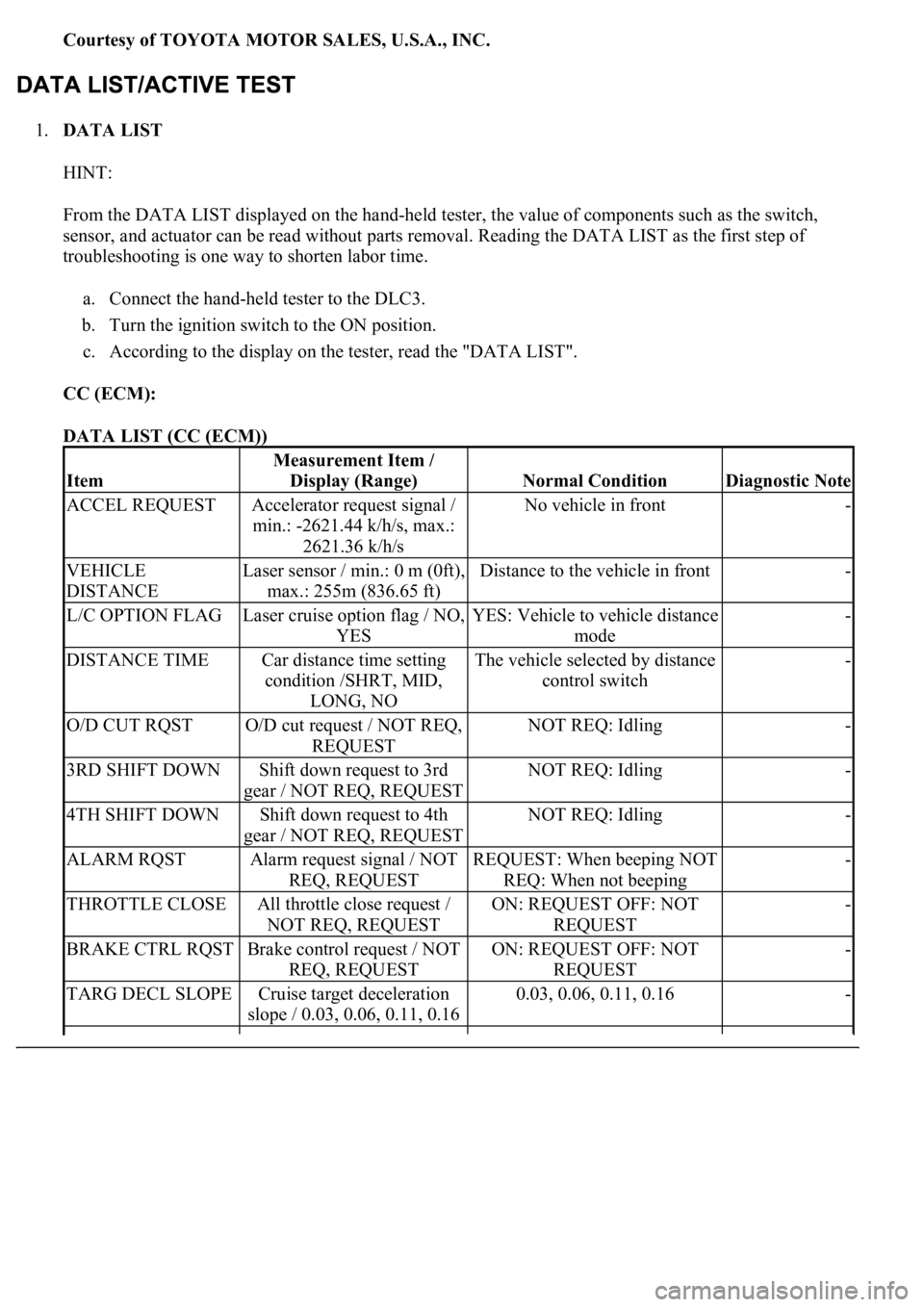
Courtesy of TOYOTA MOTOR SALES, U.S.A., INC.
1.DATA LIST
HINT:
From the DATA LIST displayed on the hand-held tester, the value of components such as the switch,
sensor, and actuator can be read without parts removal. Reading the DATA LIST as the first step of
troubleshooting is one way to shorten labor time.
a. Connect the hand-held tester to the DLC3.
b. Turn the ignition switch to the ON position.
c. According to the display on the tester, read the "DATA LIST".
CC (ECM):
DATA LIST (CC (ECM))
Item
Measurement Item /
Display (Range)
Normal ConditionDiagnostic Note
ACCEL REQUESTAccelerator request signal /
min.: -2621.44 k/h/s, max.:
2621.36 k/h/sNo vehicle in front-
VEHICLE
DISTANCELaser sensor / min.: 0 m (0ft),
max.: 255m (836.65 ft)Distance to the vehicle in front-
L/C OPTION FLAGLaser cruise option flag / NO,
YESYES: Vehicle to vehicle distance
mode-
DISTANCE TIMECar distance time setting
condition /SHRT, MID,
LONG, NOThe vehicle selected by distance
control switch-
O/D CUT RQSTO/D cut request / NOT REQ,
REQUESTNOT REQ: Idling-
3RD SHIFT DOWNShift down request to 3rd
gear / NOT REQ, REQUESTNOT REQ: Idling-
4TH SHIFT DOWNShift down request to 4th
gear / NOT REQ, REQUESTNOT REQ: Idling-
ALARM RQSTAlarm request signal / NOT
REQ, REQUESTREQUEST: When beeping NOT
REQ: When not beeping-
THROTTLE CLOSEAll throttle close request /
NOT REQ, REQUESTON: REQUEST OFF: NOT
REQUEST-
BRAKE CTRL RQSTBrake control request / NOT
REQ, REQUESTON: REQUEST OFF: NOT
REQUEST-
TARG DECL SLOPECruise target deceleration
slope / 0.03, 0.06, 0.11, 0.160.03, 0.06, 0.11, 0.16-