Page 2621 of 4500
OK: Go To Next Step.
2.READ VALUE ON HAND-HELD TESTER
a. Connect the hand-held tester to the DLC3.
b. Turn the ignition switch to the ON position, and turn the hand-held tester main switch on.
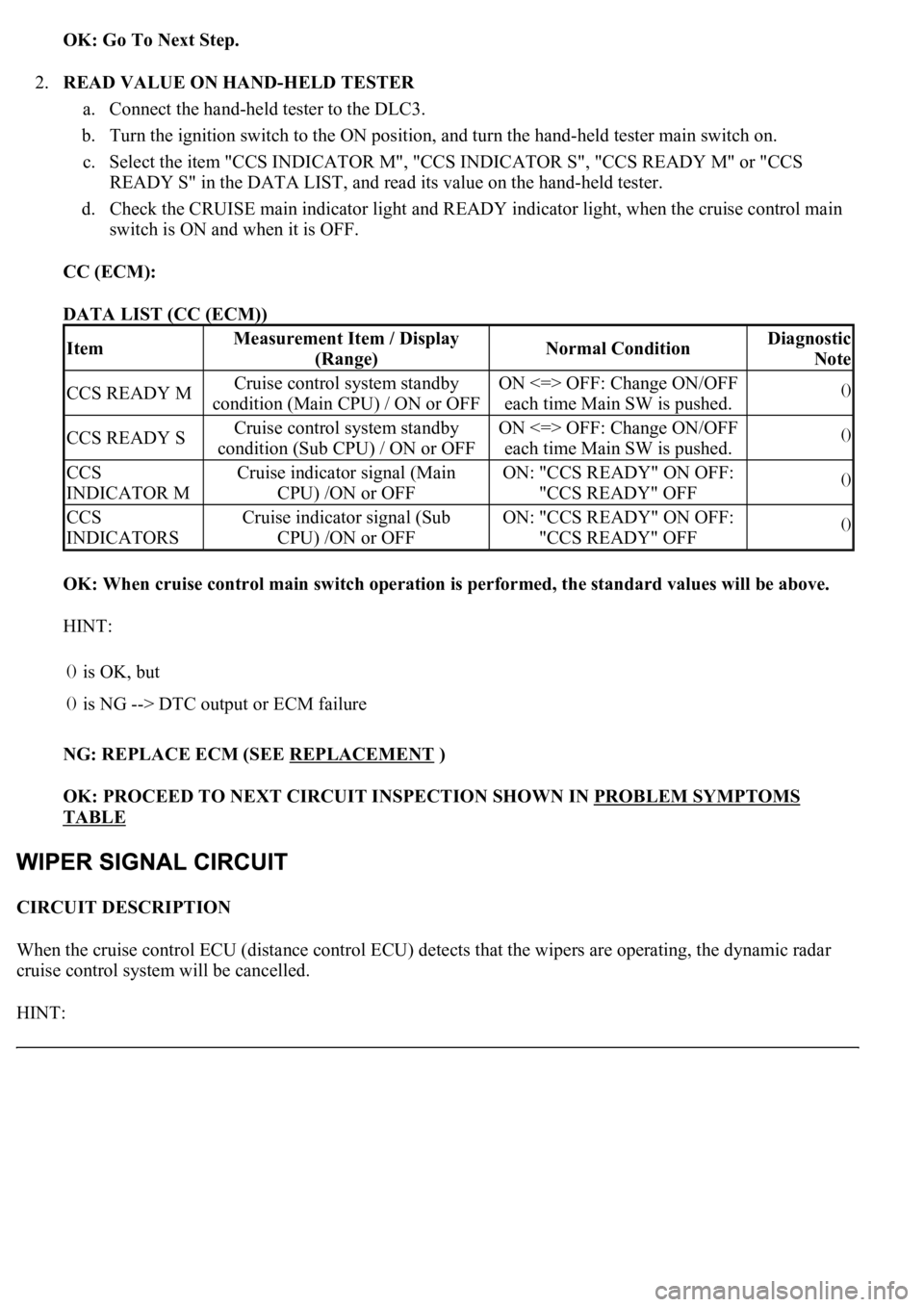
c. Select the item "CCS INDICATOR M", "CCS INDICATOR S", "CCS READY M" or "CCS
READY S" in the DATA LIST, and read its value on the hand-held tester.
d. Check the CRUISE main indicator light and READY indicator light, when the cruise control main
switch is ON and when it is OFF.
CC (ECM):
DATA LIST (CC (ECM))
OK: When cruise control main switch operation is performed, the standard values will be above.
HINT:
NG: REPLACE ECM (SEE REPLACEMENT
)
OK: PROCEED TO NEXT CIRCUIT INSPECTION SHOWN IN PROBLEM SYMPTOMS
TABLE
CIRCUIT DESCRIPTION
When the cruise control ECU (distance control ECU) detects that the wipers are operating, the dynamic radar
cruise control system will be cancelled.
HINT:
ItemMeasurement Item / Display
(Range)Normal ConditionDiagnostic
Note
CCS READY MCruise control system standby
condition (Main CPU) / ON or OFFON <=> OFF: Change ON/OFF
each time Main SW is pushed.()
CCS READY SCruise control system standby
condition (Sub CPU) / ON or OFFON <=> OFF: Change ON/OFF
each time Main SW is pushed.()
CCS
INDICATOR MCruise indicator signal (Main
CPU) /ON or OFFON: "CCS READY" ON OFF:
"CCS READY" OFF()
CCS
INDICATORSCruise indicator signal (Sub
CPU) /ON or OFFON: "CCS READY" ON OFF:
"CCS READY" OFF()
()
is OK, but
()is NG --> DTC output or ECM failure
Page 2729 of 4500
CIRCUIT DESCRIPTION
The park/neutral position switch detects the shift lever position and sends signals to the ECM.
Fig. 49: DTC Reference Chart
Courtesy of TOYOTA MOTOR SALES, U.S.A., INC.
MONITOR DESCRIPTION
These DTCs indicate a problem with the park/neutral position switch and the wire harness in the park/neutral
position switch circuit.
The park/neutral position switch detects the shift lever position and sends signals to the ECM.
For security, the park/neutral position switch detects the shift lever position so that engine can be started only
when the vehicle is in P or N shift position.
When the park/neutral position switch sends more than one signal at a time from switch positions P, R, N or D,
the ECM interprets this as a fault in the switch. The ECM will turn on the MIL and store the DTC.
MONITOR STRATEGY
P0705:
MONITOR STRATEGY TABLE - P0705
Related DTCsP0705: Park/neutral position switch/Verify switch
input
Page 2751 of 4500
It is not necessary to inspect the circuit when P0711 is set.
1.CHECK OTHER DTCS OUTPUT (IN ADDITION TO DTC P0711)
a. Connect the hand-held tester to the DLC3.
b. Turn the ignition switch to the ON position and push the hand-held tester main switch ON.
c. Select the item "DIAGNOSIS/ENHANCED OBD II/DTC INFO/CURRENT CODES".
d. Read the DTCs using the hand-held tester.
Result:
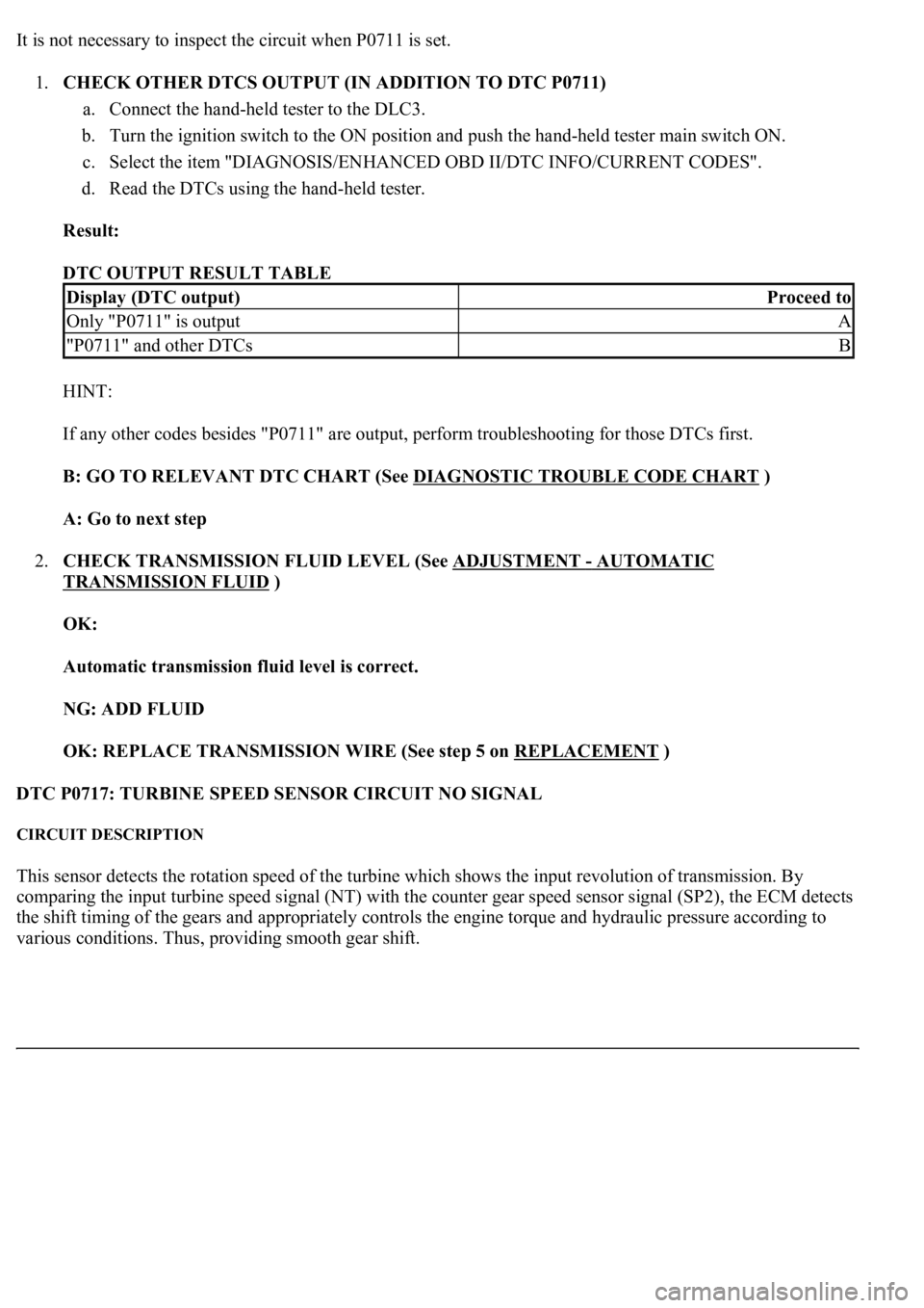
DTC OUTPUT RESULT TABLE
HINT:
If any other codes besides "P0711" are output, perform troubleshooting for those DTCs first.
B: GO TO RELEVANT DTC CHART (See DIAGNOSTIC TROUBLE CODE CHART
)
A: Go to next step
2.CHECK TRANSMISSION FLUID LEVEL (See ADJUSTMENT
- AUTOMATIC
TRANSMISSION FLUID )
OK:
Automatic transmission fluid level is correct.
NG: ADD FLUID
OK: REPLACE TRANSMISSION WIRE (See step 5 on REPLACEMENT
)
DTC P0717: TURBINE SPEED SENSOR CIRCUIT NO SIGNAL
CIRCUIT DESCRIPTION
This sensor detects the rotation speed of the turbine which shows the input revolution of transmission. By
comparing the input turbine speed signal (NT) with the counter gear speed sensor signal (SP2), the ECM detects
the shift timing of the gears and appropriately controls the engine torque and hydraulic pressure according to
various conditions. Thus, providin
g smooth gear shift.
Display (DTC output)Proceed to
Only "P0711" is outputA
"P0711" and other DTCsB
Page 2771 of 4500
TYPICAL MALFUNCTION THRESHOLDS TABLE
COMPONENT OPERATING RANGE
COMPONENT OPERATING RANGE TABLE
WIRING DIAGRAM
Fig. 89: DTC P0748 - Wiring Diagram
Courtesy of TOYOTA MOTOR SALES, U.S.A., INC.
INSPECTION PROCEDURE
HINT:
The shift solenoid valve SL1 is turned on/off normally when the shift lever is in the D position:
GEARSHIFT SPECIFICATION TABLE
1.INSPECT TRANSMISSION WIRE (SL1)
a. Disconnect the transmission wire connector from the transmission.
b. Measure the resistance according to the value(s) in the table below.
Standard:
Output signal duty100%
Output signal dutyLess than 100%
ECM
command
gearshift
1st2nd3rd4th5th6th
Shift solenoid
valve SL1OFFOFFOFFOFFONON
Page 2813 of 4500
COMPONENT OPERATING RANGE
COMPONENT OPERATING RANGE TABLE
WIRING DIAGRAM
Fig. 120: DTC P0778 - Wiring Diagram
Courtesy of TOYOTA MOTOR SALES, U.S.A., INC.
INSPECTION PROCEDURE
HINT:
The shift solenoid valve SL2 is turned on/off normally when the shift lever is in the D position:
GEARSHIFT SPECIFICATION TABLE
1.INSPECT TRANSMISSION WIRE (SL2)
a. Disconnect the transmission wire connector from the transmission.
b. Measure the resistance according to the value(s) in the table below.
Output signal duty100%
Output signal dutyLess than 100%
ECM
command
gearshift
1st2nd3rd4th5th6th
Shift solenoid
valve SL2ONONONONOFFOFF
Page 2820 of 4500
The ECM commands gear shifts by turning the shift solenoid valves "ON/OFF" and switching oil pressure to
the valves in the valve body.
The ECM calculates the "actual" transmission gear by comparing the signals from the input speed sensor (NT)
and the output speed sensor (SP2). The ECM can detect many mechanical problems in the shift solenoids, valve
body, and the transmission clutches, brakes, and gears. If the ECM detects that the actual gear position and the
commanded gear position are different, it will illuminate the MIL and store the DTC.
MONITOR STRATEGY
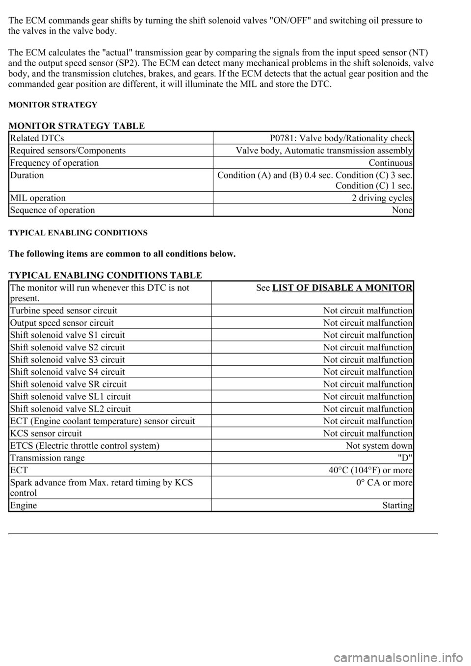
MONITOR STRATEGY TABLE
TYPICAL ENABLING CONDITIONS
The following items are common to all conditions below.
TYPICAL ENABLING CONDITIONS TABLE
Related DTCsP0781: Valve body/Rationality check
Required sensors/ComponentsValve body, Automatic transmission assembly
Frequency of operationContinuous
Duration<0026005200510047004c0057004c005200510003000b0024000c00030044005100470003000b0025000c00030013001100170003005600480046001100030026005200510047004c0057004c005200510003000b0026000c00030016000300560048004600
110003[
Condition (C) 1 sec.
MIL operation2 driving cycles
Sequence of operationNone
The monitor will run whenever this DTC is not
present.See LIST OF DISABLE A MONITOR
Turbine speed sensor circuitNot circuit malfunction
Output speed sensor circuitNot circuit malfunction
Shift solenoid valve S1 circuitNot circuit malfunction
Shift solenoid valve S2 circuitNot circuit malfunction
Shift solenoid valve S3 circuitNot circuit malfunction
Shift solenoid valve S4 circuitNot circuit malfunction
Shift solenoid valve SR circuitNot circuit malfunction
Shift solenoid valve SL1 circuitNot circuit malfunction
Shift solenoid valve SL2 circuitNot circuit malfunction
ECT (Engine coolant temperature) sensor circuitNot circuit malfunction
KCS sensor circuitNot circuit malfunction
ETCS (Electric throttle control system)Not system down
Transmission range"D"
ECT40°C (104°F) or more
Spark advance from Max. retard timing by KCS
control0° CA or more
EngineStarting
Page 3167 of 4500
3.SYSTEM FUNCTION
When the steering lock ECU detects that the unlock warning switch is ON, the ECU provides current to
the transponder key coil and produces a faint electric wave. A transponder chip in the key and receives
the faint electric wave. Upon receiving the faint electric wave, the transponder chip outputs a key ID code
signal. The transponder key coil receives this signal, the transponder key amplifier amplifies it, and then
the signal is transmitted to the ECU.
The ECU matches the key's ID code with the vehicle's ID code, which was previously registered in the
ECU and then communicates the results to the ECM using SFI communication.
After the identification results show that the key's ID code matches the vehicle's ID code and the ECU has
confirmed their match: 1) the immobilizer system does not immobilize the engine and the engine starting
controls (fuel injection control and ignition control) enter standby mode; and 2) the ECU transmits a
security indicator signal that communicates "indicator off" to the theft warning ECU (theft deterrent
ECU). Then, the theft warning ECU turns off the security indicator lamp.
HINT:
Use this procedure to troubleshoot the engine immobilizer system.
The hand-held tester should be used in steps 4, 5 and 7.
1.VEHICLE BROUGHT TO WORKSHOP
2.CUSTOMER PROBLEM ANALYSIS CHECK AND SYMPTOM CHECK (See CUSTOMER
PROBLEM ANALYSIS CHECK )
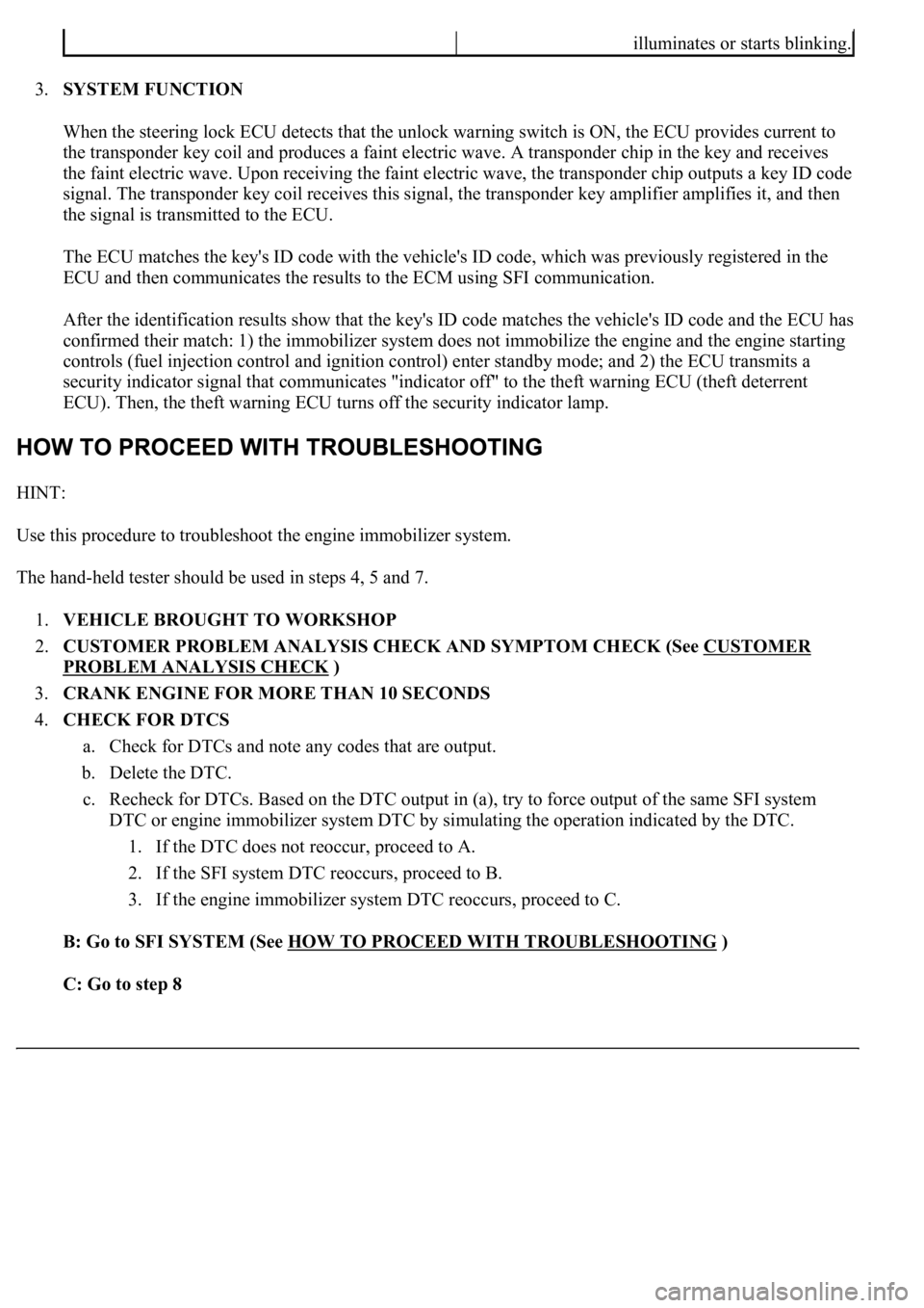
3.CRANK ENGINE FOR MORE THAN 10 SECONDS
4.CHECK FOR DTCS
a. Check for DTCs and note any codes that are output.
b. Delete the DTC.
c. Recheck for DTCs. Based on the DTC output in (a), try to force output of the same SFI system
DTC or engine immobilizer system DTC by simulating the operation indicated by the DTC.
1. If the DTC does not reoccur, proceed to A.
2. If the SFI system DTC reoccurs, proceed to B.
3. If the engine immobilizer system DTC reoccurs, proceed to C.
B: Go to SFI SYSTEM (See HOW TO PROCEED WITH TROUBLESHOOTING
)
C: Go to step 8
illuminates or starts blinking.
Page 3168 of 4500
A: Go to next step
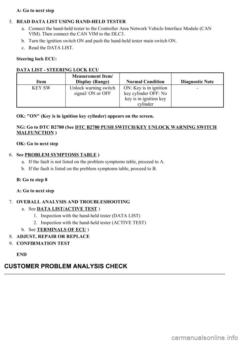
5.READ DATA LIST USING HAND-HELD TESTER
a. Connect the hand-held tester to the Controller Area Network Vehicle Interface Module (CAN
VIM). Then connect the CAN VIM to the DLC3.
b. Turn the ignition switch ON and push the hand-held tester main switch ON.
c. Read the DATA LIST.
Steering lock ECU:
DATA LIST - STEERING LOCK ECU
OK: "ON" (Key is in ignition key cylinder) appears on the screen.
NG: Go to DTC B2780 (See DTC B2780 PUSH SWITCH/KEY UNLOCK WARNING SWITCH
MALFUNCTION )
OK: Go to next step
6.See PROBLEM SYMPTOMS TABLE
)
a. If the fault is not listed on the problem symptoms table, proceed to A.
b. If the fault is listed on the problem symptoms table, proceed to B.
B: Go to step 8
A: Go to next step
7.OVERALL ANALYSIS AND TROUBLESHOOTING
a. See DATA LIST/ACTIVE TEST
)
1. Inspection with the hand-held tester (DATA LIST)
2. Inspection with the hand-held tester (ACTIVE TEST)
b. See TERMINALS OF ECU
)
8.ADJUST, REPAIR OR REPLACE
9.CONFIRMATION TEST
END
Item
Measurement Item/
Display (Range)
Normal ConditionDiagnostic Note
KEY SWUnlock warning switch
signal/ ON or OFFON: Key is in ignition
key cylinder OFF: No
key is in ignition key
cylinder-