Page 1920 of 4500

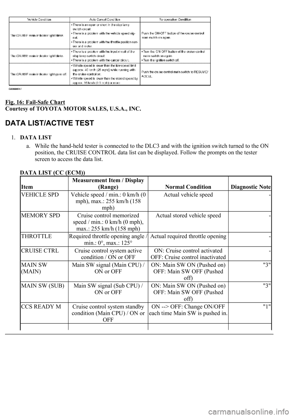
Fig. 16: Fail-Safe Chart
Courtesy of TOYOTA MOTOR SALES, U.S.A., INC.
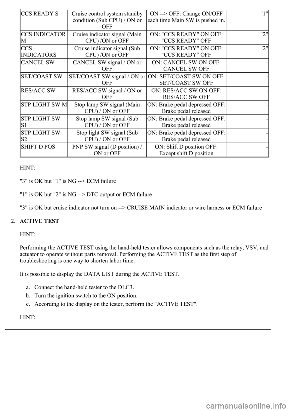
1.DATA LIST
a. While the hand-held tester is connected to the DLC3 and with the ignition switch turned to the ON
position, the CRUISE CONTROL data list can be displayed. Follow the prompts on the tester
screen to access the data list.
DATA LIST (CC (ECM))
Item
Measurement Item / Display
(Range)
Normal ConditionDiagnostic Note
VEHICLE SPDVehicle speed / min.: 0 km/h (0
mph), max.: 255 km/h (158
mph)Actual vehicle speed-
MEMORY SPDCruise control memorized
speed / min.: 0 km/h (0 mph),
max.: 255 km/h (158 mph)Actual stored vehicle speed-
THROTTLERequired throttle opening angle /
min.: 0°, max.: 125°Actual required throttle opening-
CRUISE CTRLCruise control system active
condition / ON or OFFON: Cruise control activated
OFF: Cruise control inactivated-
MAIN SW
(MAIN)Main SW signal (Main CPU) /
ON or OFFON: Main SW ON (Pushed on)
OFF: Main SW OFF (Pushed
off)"3"
MAIN SW (SUB)Main SW signal (Sub CPU) /
ON or OFFON: Main SW ON (Pushed on)
OFF: Main SW OFF (Pushed
off)"3"
CCS READY MCruise control system standby
condition (Main CPU) / ON or
OFFON --> OFF: Change ON/OFF
each time Main SW is pushed in."1"
Page 1921 of 4500

HINT:
"3" is OK but "1" is NG --> ECM failure
"1" is OK but "2" is NG --> DTC output or ECM failure
"3" is OK but cruise indicator not turn on --> CRUISE MAIN indicator or wire harness or ECM failure
2.ACTIVE TEST
HINT:
Performing the ACTIVE TEST using the hand-held tester allows components such as the relay, VSV, and
actuator to operate without parts removal. Performing the ACTIVE TEST as the first step of
troubleshooting is one way to shorten labor time.
It is possible to display the DATA LIST during the ACTIVE TEST.
a. Connect the hand-held tester to the DLC3.
b. Turn the ignition switch to the ON position.
c. According to the display on the tester, perform the "ACTIVE TEST".
HINT:
CCS READY SCruise control system standby
condition (Sub CPU) / ON or
OFFON --> OFF: Change ON/OFF
each time Main SW is pushed in."1"
CCS INDICATOR
MCruise indicator signal (Main
CPU) /ON or OFFON: "CCS READY" ON OFF:
"CCS READY" OFF"2"
CCS
INDICATORSCruise indicator signal (Sub
CPU) /ON or OFFON: "CCS READY" ON OFF:
"CCS READY" OFF"2"
CANCEL SWCANCEL SW signal / ON or
OFFON: CANCEL SW ON OFF:
CANCEL SW OFF-
SET/COAST SWSET/COAST SW signal / ON or
OFFON: SET/COAST SW ON OFF:
SET/COAST SW OFF-
RES/ACC SWRES/ACC SW signal / ON or
OFFON: RES/ACC SW ON OFF:
RES/ACC SW OFF-
STP LIGHT SW MStop lamp SW signal (Main
CPU) / ON or OFFON: Brake pedal depressed OFF:
Brake pedal released-
STP LIGHT SW
S1Stop lamp SW signal (Sub
CPU) / ON or OFFON: Brake pedal depressed OFF:
Brake pedal released-
STP LIGHT SW
S2Stop light SW signal (Sub
CPU) / ON or OFFON: Brake pedal depressed OFF:
Brake pedal released-
SHIFT D POSPNP SW signal (D position) /
ON or OFFON: Shift D position OFF:
Except shift D position-
Page 1922 of 4500
The ignition switch must be turned to the ON position to proceed ACTIVE TEST using the hand-held
tester.
ACTIVE TEST DETAIL (COMBINATION METER ASSY)
HINT:
If a trouble code is displayed during the DTC check, check the circuit listed for that code. For details of each
code, refer to chart.
DIAGNOSTIC TROUBLE CODE CHART
Fig. 17: Diagnostic Trouble Code Information Chart
Courtesy of TOYOTA MOTOR SALES, U.S.A., INC.
CIRCUIT DESCRIPTION
See CIRCUIT DESCRIPTION
.
ItemVehicle Condition / Test DetailsDiagnostic Note
CRUISE INDIC"CRUISE" indicator is ON / OFF-
DTCDescription
DTC P0500 VEHICLE SPEED SENSOR CIRCUIT MALFUNCTION
DTC P0503 VEHICLE SPEED SENSOR CIRCUIT MALFUNCTION
DTC P0571 STOP LIGHT SWITCH CIRCUIT MALFUNCTION
DTC P0607 INPUT SIGNAL CIRCUIT MALFUNCTION
Page 1923 of 4500
Fig. 18: DTC P0500 And P0503 Problem Symptom Diagnostic Chart
Courtesy of TOYOTA MOTOR SALES, U.S.A., INC.
WIRING DIAGRAM
See WIRING DIAGRAM
INSPECTION PROCEDURE
See INSPECTION PROCEDURE
.
CIRCUIT DESCRIPTION
When the brake pedal is depressed, the stop lamp switch assy sends a signal to the ECM. When the ECM
receives this signal, it cancels the cruise control.
Fail-safe function operates to enable normal driving even if there is a malfunction in the stop lamp signal
circuit.
The cancel condition occurs when positive battery voltage is applied to terminal STP.
When the brake is applied, battery positive voltage is normally applied to terminal STP of the ECM through the
STOP fuse and the stop lamp switch assy, and the ECM turns the cruise control off.
Fig. 19: DTC P0571 Problem Symptom Diagnostic Chart
Courtesy of TOYOTA MOTOR SALES, U.S.A., INC.
WIRING DIAGRAM
Page 1925 of 4500

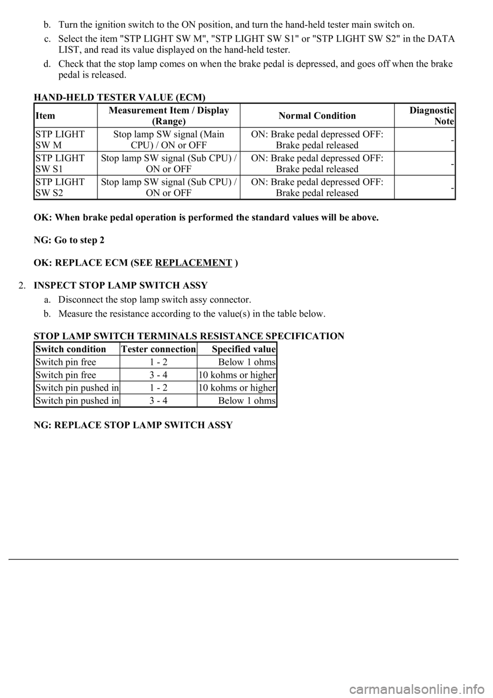
b. Turn the ignition switch to the ON position, and turn the hand-held tester main switch on.
c. Select the item "STP LIGHT SW M", "STP LIGHT SW S1" or "STP LIGHT SW S2" in the DATA
LIST, and read its value displayed on the hand-held tester.
d. Check that the stop lamp comes on when the brake pedal is depressed, and goes off when the brake
pedal is released.
HAND-HELD TESTER VALUE (ECM)
OK: When brake pedal operation is performed the standard values will be above.
NG: Go to step 2
OK: REPLACE ECM (SEE REPLACEMENT
)
2.INSPECT STOP LAMP SWITCH ASSY
a. Disconnect the stop lamp switch assy connector.
b. Measure the resistance according to the value(s) in the table below.
STOP LAMP SWITCH TERMINALS RESISTANCE SPECIFICATION
NG: REPLACE STOP LAMP SWITCH ASSY
ItemMeasurement Item / Display
(Range)Normal ConditionDiagnostic
Note
STP LIGHT
SW MStop lamp SW signal (Main
CPU) / ON or OFFON: Brake pedal depressed OFF:
Brake pedal released-
STP LIGHT
SW S1Stop lamp SW signal (Sub CPU) /
ON or OFFON: Brake pedal depressed OFF:
Brake pedal released-
STP LIGHT
SW S2Stop lamp SW signal (Sub CPU) /
ON or OFFON: Brake pedal depressed OFF:
Brake pedal released-
Switch conditionTester connectionSpecified value
Switch pin free1 - 2Below 1 ohms
Switch pin free3 - 410 kohms or higher
Switch pin pushed in1 - 210 kohms or higher
Switch pin pushed in3 - 4Below 1 ohms
Page 1932 of 4500

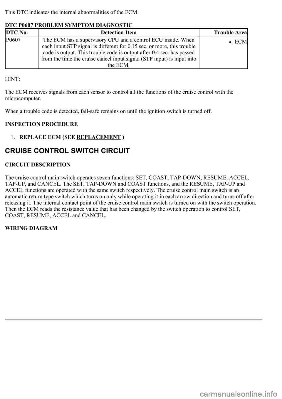
This DTC indicates the internal abnormalities of the ECM.
DTC P0607 PROBLEM SYMPTOM DIAGNOSTIC
HINT:
The ECM receives signals from each sensor to control all the functions of the cruise control with the
microcomputer.
When a trouble code is detected, fail-safe remains on until the ignition switch is turned off.
INSPECTION PROCEDURE
1.REPLACE ECM (SEE REPLACEMENT
)
CIRCUIT DESCRIPTION
The cruise control main switch operates seven functions: SET, COAST, TAP-DOWN, RESUME, ACCEL,
TAP-UP, and CANCEL. The SET, TAP-DOWN and COAST functions, and the RESUME, TAP-UP and
ACCEL functions are operated with the same switch respectively. The cruise control main switch is an
automatic return type switch which turns on only while operating it in each arrow direction and turns off after
releasing it. The internal contact point of the cruise control main switch is turned on with the switch operation.
Then the ECM reads the resistance value that has been changed by the switch operation to control SET,
COAST, RESUME, ACCEL and CANCEL.
WIRING DIAGRAM
DTC No.Detection ItemTrouble Area
P0607The ECM has a supervisory CPU and a control ECU inside. When
each input STP signal is different for 0.15 sec. or more, this trouble
code is output. This trouble code is output after 0.4 sec. has passed
from the time the cruise cancel input signal (STP input) is input into
the ECM.ECM
Page 1940 of 4500
![LEXUS LS430 2003 Factory Repair Manual Fig. 31: [Disconnecting ECM Connector]
Courtesy of TOYOTA MOTOR SALES, U.S.A., INC.
NG: REPAIR OR REPLACE HARNESS OR CONNECTOR
OK: REPLACE ECM (SEE REPLACEMENT
)
CIRCUIT DESCRIPTION
The ECM det LEXUS LS430 2003 Factory Repair Manual Fig. 31: [Disconnecting ECM Connector]
Courtesy of TOYOTA MOTOR SALES, U.S.A., INC.
NG: REPAIR OR REPLACE HARNESS OR CONNECTOR
OK: REPLACE ECM (SEE REPLACEMENT
)
CIRCUIT DESCRIPTION
The ECM det](/manual-img/36/57050/w960_57050-1939.png)
Fig. 31: [Disconnecting ECM Connector]
Courtesy of TOYOTA MOTOR SALES, U.S.A., INC.
NG: REPAIR OR REPLACE HARNESS OR CONNECTOR
OK: REPLACE ECM (SEE REPLACEMENT
)
CIRCUIT DESCRIPTION
The ECM detects a cruise control switch signal and sends it to the combination meter via CAN and
BEAN. Then the CRUISE main indicator light comes on.
The CRUISE main indicator light circuit uses CAN and BEAN for communication. If there are any
malfunctions in this circuit, check for DTCs in the CAN communication system and multiplex
communication system.
INSPECTION PROCEDURE
1.PERFORM ACTIVE TEST BY HAND-HELD TESTER
a. Connect the hand-held tester to the DLC3.
b. Check the CRUISE main indicator light by using ACTIVE TEST.
ACTIVE TEST DETAIL (COMBINATION METER ASSY)
OK: Indicator light comes on/goes off.
NG: GO TO COMBINATION METER SYSTEM (SEE HOW TO PROCEED WITH
TROUBLESHOOTING )
OK: Go to next step
2.READ VALUE ON HAND-HELD TESTER
a. Connect the hand-held tester to the DLC3.
b. Turn the ignition switch to the ON position and turn the hand-held tester main switch on.
c. Select the item below in the "DATA LIST", and read the display on the hand-held tester.
DATA LIST (CC (ECM))
ItemVehicle Condition / Test DetailsDiagnostic Note
CRUISE INDIC"CRUISE" indicator is ON / OFF-
ItemMeasurement Item / Display
(Range)Normal ConditionDiagnostic
Note
CCS INDICATOR
MCruise indicator signal (Main
CPU) /ON or OFFON: "CCS READY" ON OFF:
"CCS READY" OFF-
Page 1991 of 4500
Fig. 2: Defogger System Diagram
Courtesy of TOYOTA MOTOR SALES, U.S.A., INC.
Communication Table
COMMUNICATION TABLE
1.GENERAL
The rear window defogger system's thin heater wires are attached to the inside of the rear window and
defog the window surface quickly. The indicator lamp illuminates while the system is operating. The
system automatically turns off after approximately 15 minutes.
2.FUNCTION OF MAIN COMPONENT
SenderReceiverSignalLine
Multi-display(1)A/C control assemblyRear defogger switch
signalBEAN
Center cluster integration
panel
(2)
A/C control assemblyRear defogger switch
signalBEAN/AVC-LAN
(1)w/ LEXUS navigation system
(2)w/o LEXUS navigation system