2003 LEXUS LS430 turn signal
[x] Cancel search: turn signalPage 1005 of 4500
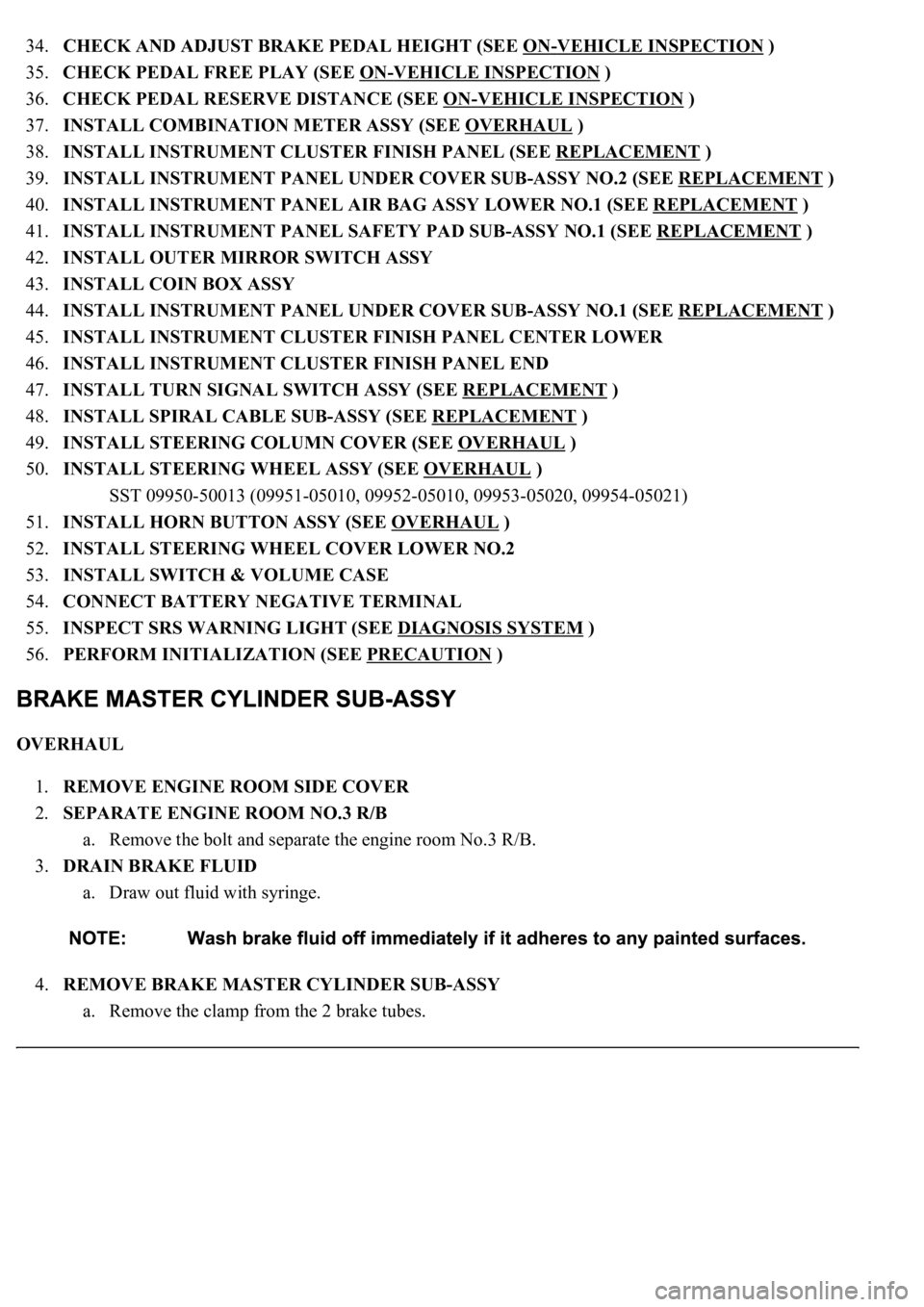
34.CHECK AND ADJUST BRAKE PEDAL HEIGHT (SEE ON-VEHICLE INSPECTION )
35.CHECK PEDAL FREE PLAY (SEE ON
-VEHICLE INSPECTION )
36.CHECK PEDAL RESERVE DISTANCE (SEE ON
-VEHICLE INSPECTION )
37.INSTALL COMBINATION METER ASSY (SEE OVERHAUL
)
38.INSTALL INSTRUMENT CLUSTER FINISH PANEL (SEE REPLACEMENT
)
39.INSTALL INSTRUMENT PANEL UNDER COVER SUB-ASSY NO.2 (SEE REPLACEMENT
)
40.INSTALL INSTRUMENT PANEL AIR BAG ASSY LOWER NO.1 (SEE REPLACEMENT
)
41.INSTALL INSTRUMENT PANEL SAFETY PAD SUB-ASSY NO.1 (SEE REPLACEMENT
)
42.INSTALL OUTER MIRROR SWITCH ASSY
43.INSTALL COIN BOX ASSY
44.INSTALL INSTRUMENT PANEL UNDER COVER SUB-ASSY NO.1 (SEE REPLACEMENT
)
45.INSTALL INSTRUMENT CLUSTER FINISH PANEL CENTER LOWER
46.INSTALL INSTRUMENT CLUSTER FINISH PANEL END
47.INSTALL TURN SIGNAL SWITCH ASSY (SEE REPLACEMENT
)
48.INSTALL SPIRAL CABLE SUB-ASSY (SEE REPLACEMENT
)
49.INSTALL STEERING COLUMN COVER (SEE OVERHAUL
)
50.INSTALL STEERING WHEEL ASSY (SEE OVERHAUL
)
<00360036003700030013001c001c001800130010001800130013001400160003000b0013001c001c00180014001000130018001300140013000f00030013001c001c00180015001000130018001300140013000f00030013001c001c001800160010001300
18001300150013000f00030013001c001c0018001700100013[5021)
51.INSTALL HORN BUTTON ASSY (SEE OVERHAUL
)
52.INSTALL STEERING WHEEL COVER LOWER NO.2
53.INSTALL SWITCH & VOLUME CASE
54.CONNECT BATTERY NEGATIVE TERMINAL
55.INSPECT SRS WARNING LIGHT (SEE DIAGNOSIS SYSTEM
)
56.PERFORM INITIALIZATION (SEE PRECAUTION
)
OVERHAUL
1.REMOVE ENGINE ROOM SIDE COVER
2.SEPARATE ENGINE ROOM NO.3 R/B
a. Remove the bolt and separate the engine room No.3 R/B.
3.DRAIN BRAKE FLUID
a. Draw out fluid with syringe.
4.REMOVE BRAKE MASTER CYLINDER SUB-ASSY
a. Remove the clamp from the 2 brake tubes.
Page 1503 of 4500
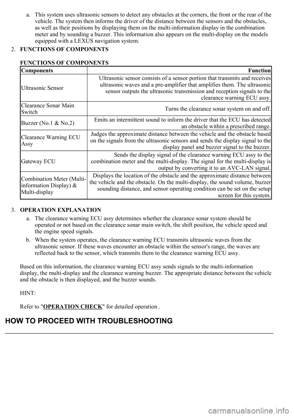
a. This system uses ultrasonic sensors to detect any obstacles at the corners, the front or the rear of the
vehicle. The system then informs the driver of the distance between the sensors and the obstacles,
as well as their positions by displaying them on the multi-information display in the combination
meter and by sounding a buzzer. This information also appears on the multi-display on the models
equipped with a LEXUS navigation system.
2.FUNCTIONS OF COMPONENTS
FUNCTIONS OF COMPONENTS
3.OPERATION EXPLANATION
a. The clearance warning ECU assy determines whether the clearance sonar system should be
operated or not based on the clearance sonar main switch, the shift position, the vehicle speed and
the engine speed signals.
b. When the system operates, the clearance warning ECU transmits ultrasonic waves from the
ultrasonic sensor. If these waves encounter an obstacle within the sensor's range, the waves are
reflected back to the sensor, which transmits them to the clearance warning ECU assy.
Based on this information, the clearance warning ECU assy sends signals to the multi-information
display, the multi-display and the clearance warning buzzer. The appropriate distance between the vehicle
and the obstacle is then displayed, and the buzzer sounds.
HINT:
Refer to "OPERATION CHECK
" for detailed operation .
ComponentsFunction
Ultrasonic Sensor
Ultrasonic sensor consists of a sensor portion that transmits and receives
ultrasonic waves and a pre-amplifier that amplifies them. The ultrasonic
sensor outputs the ultrasonic transmission and reception signals to the
clearance warning ECU assy.
Clearance Sonar Main
SwitchTurns the clearance sonar system on and off.
Buzzer (No.1 & No.2)Emits an intermittent sound to inform the driver that the ECU has detected
an obstacle within a prescribed range.
Clearance Warning ECU
AssyJudges the approximate distance between the vehicle and the obstacle based
on the signals from the ultrasonic sensors and sends the display signal to the
display panel and buzzer signal to the buzzer.
Gateway ECU
Sends the display signal of the clearance warning ECU assy to the
combination meter and the multi-display. The signal for the multi-display is
output by converting it to an AVC-LAN signal.
Combination Meter (Multi-
information Display) &
Multi-displayDisplays the location of the obstacle and the approximate distance between
the vehicle and the obstacle. On the multi-display, the sound volume, buzzer
sounding distance, and sensor operating condition can be set on the setup
screen for this system.
Page 1595 of 4500
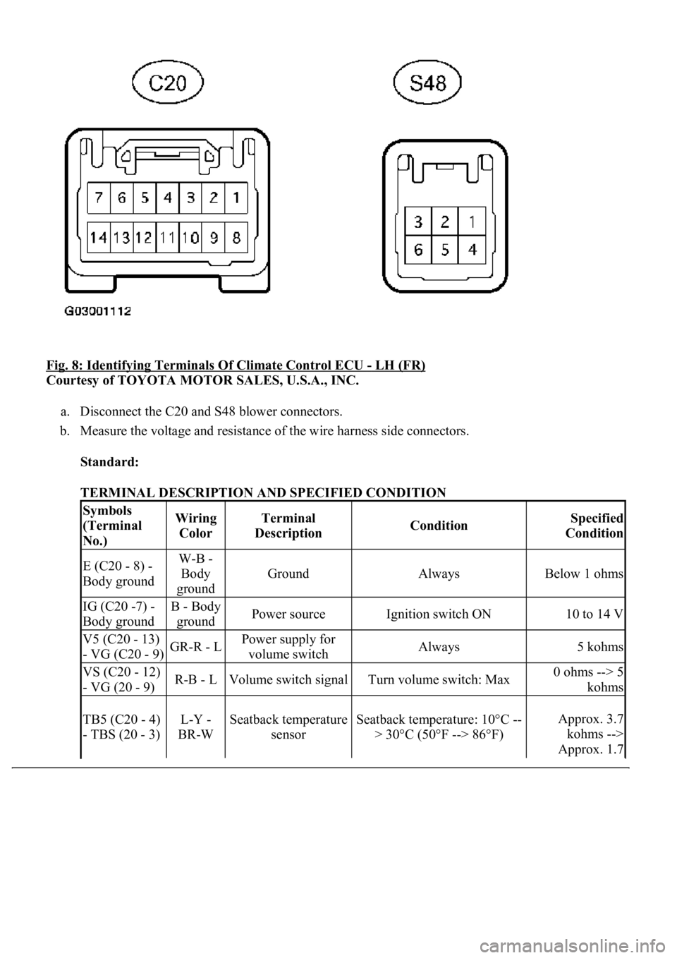
Fig. 8: Identifying Terminals Of Climate Control ECU - LH (FR)
Courtesy of TOYOTA MOTOR SALES, U.S.A., INC.
a. Disconnect the C20 and S48 blower connectors.
b. Measure the voltage and resistance of the wire harness side connectors.
Standard:
TERMINAL DESCRIPTION AND SPECIFIED CONDITION
Symbols
(Terminal
No.)Wiring
ColorTerminal
DescriptionConditionSpecified
Condition
E (C20 - 8) -
Body groundW-B -
Body
ground
GroundAlwaysBelow 1 ohms
IG (C20 -7) -
Body groundB - Body
groundPower sourceIgnition switch ON10 to 14 V
V5 (C20 - 13)
- VG (C20 - 9)GR-R - LPower supply for
volume switchAlways5 kohms
VS (C20 - 12)
- VG (20 - 9)R-B - LVolume switch signalTurn volume switch: Max0 ohms --> 5
kohms
TB5 (C20 - 4)
- TBS (20 - 3)L-Y -
BR-WSeatback temperature
sensorSeatback temperature: 10°C --
> 30°C (50°F --> 86°F)Approx. 3.7
kohms -->
Approx. 1.7
Page 1596 of 4500
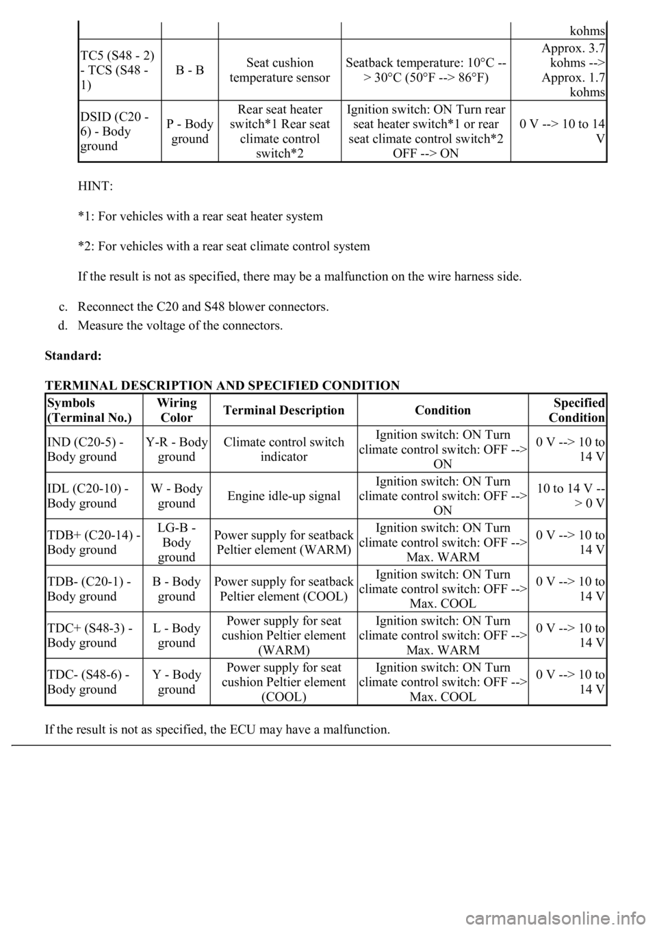
HINT:
*1: For vehicles with a rear seat heater system
*2: For vehicles with a rear seat climate control system
If the result is not as specified, there may be a malfunction on the wire harness side.
c. Reconnect the C20 and S48 blower connectors.
d. Measure the voltage of the connectors.
Standard:
TERMINAL DESCRIPTION AND SPECIFIED CONDITION
If the result is not as specified, the ECU ma
y have a malfunction.
kohms
TC5 (S48 - 2)
- TCS (S48 -
1)
B - BSeat cushion
temperature sensorSeatback temperature: 10°C --
> 30°C (50°F --> 86°F)
Approx. 3.7
kohms -->
Approx. 1.7
kohms
DSID (C20 -
6) - Body
groundP - Body
ground
Rear seat heater
switch*1 Rear seat
climate control
switch*2Ignition switch: ON Turn rear
seat heater switch*1 or rear
seat climate control switch*2
OFF --> ON
0 V --> 10 to 14
V
Symbols
(Terminal No.)Wiring
ColorTerminal DescriptionConditionSpecified
Condition
IND (C20-5) -
Body groundY-R - Body
groundClimate control switch
indicatorIgnition switch: ON Turn
climate control switch: OFF -->
ON0 V --> 10 to
14 V
IDL (C20-10) -
Body groundW - Body
groundEngine idle-up signal
Ignition switch: ON Turn
climate control switch: OFF -->
ON10 to 14 V --
> 0 V
TDB+ (C20-14) -
Body groundLG-B -
Body
groundPower supply for seatback
Peltier element (WARM)Ignition switch: ON Turn
climate control switch: OFF -->
Max. WARM0 V --> 10 to
14 V
TDB- (C20-1) -
Body groundB - Body
groundPower supply for seatback
Peltier element (COOL)Ignition switch: ON Turn
climate control switch: OFF -->
Max. COOL0 V --> 10 to
14 V
TDC+ (S48-3) -
Body groundL - Body
groundPower supply for seat
cushion Peltier element
(WARM)Ignition switch: ON Turn
climate control switch: OFF -->
Max. WARM0 V --> 10 to
14 V
TDC- (S48-6) -
Body groundY - Body
groundPower supply for seat
cushion Peltier element
(COOL)Ignition switch: ON Turn
climate control switch: OFF -->
Max. COOL0 V --> 10 to
14 V
Page 1597 of 4500
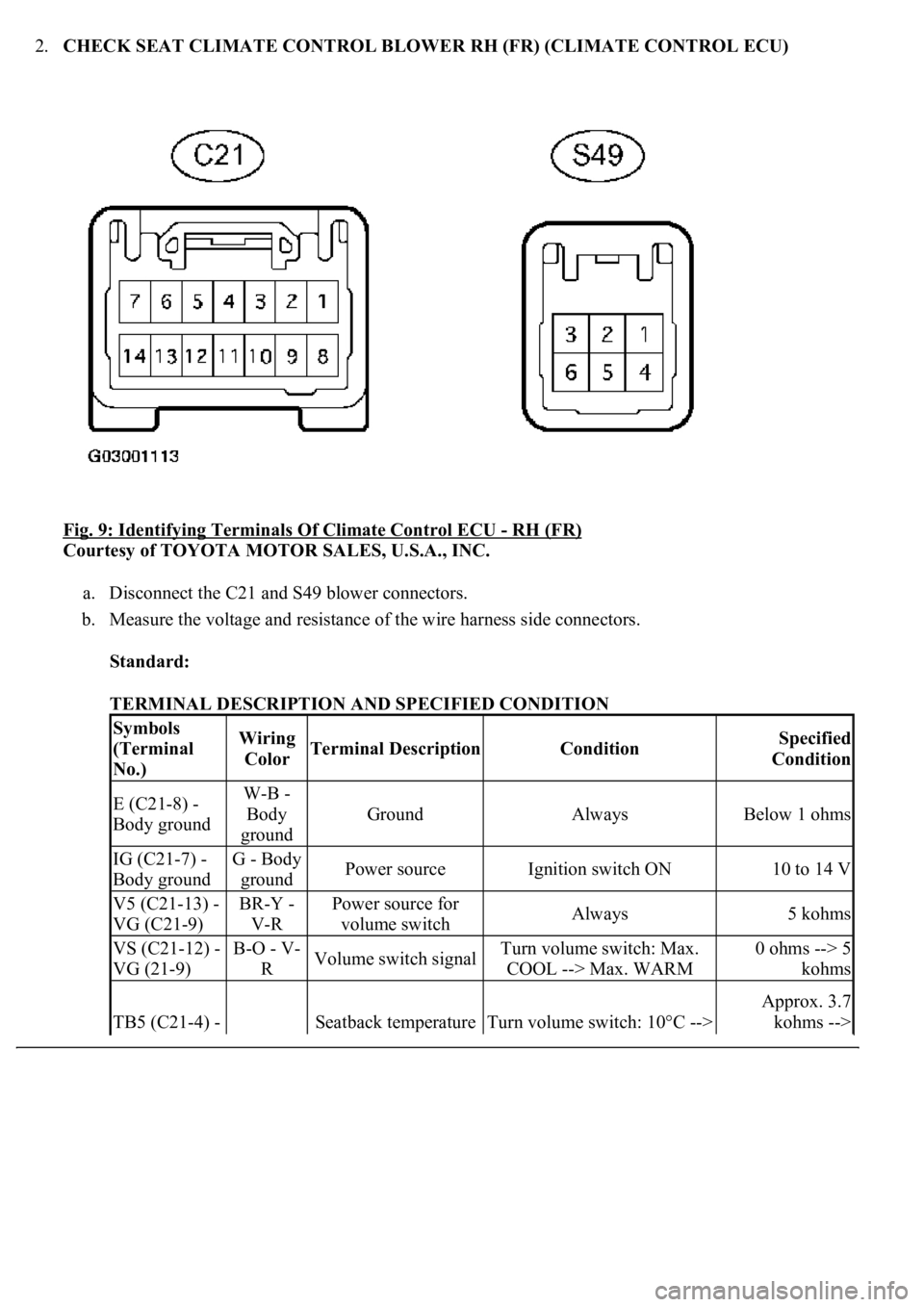
2.CHECK SEAT CLIMATE CONTROL BLOWER RH (FR) (CLIMATE CONTROL ECU)
Fig. 9: Identifying Terminals Of Climate Control ECU
- RH (FR)
Courtesy of TOYOTA MOTOR SALES, U.S.A., INC.
a. Disconnect the C21 and S49 blower connectors.
b. Measure the voltage and resistance of the wire harness side connectors.
Standard:
TERMINAL DESCRIPTION AND SPECIFIED CONDITION
Symbols
(Terminal
No.)Wiring
ColorTerminal DescriptionConditionSpecified
Condition
E (C21-8) -
Body groundW-B -
Body
ground
GroundAlwaysBelow 1 ohms
IG (C21-7) -
Body groundG - Body
groundPower sourceIgnition switch ON10 to 14 V
V5 (C21-13) -
VG (C21-9)BR-Y -
V-RPower source for
volume switchAlways5 kohms
VS (C21-12) -
VG (21-9)B-O - V-
RVolume switch signalTurn volume switch: Max.
COOL --> Max. WARM0 ohms --> 5
kohms
TB5 (C21-4) - Seatback temperature Turn volume switch: 10°C -->
Approx. 3.7
kohms -->
Page 1599 of 4500
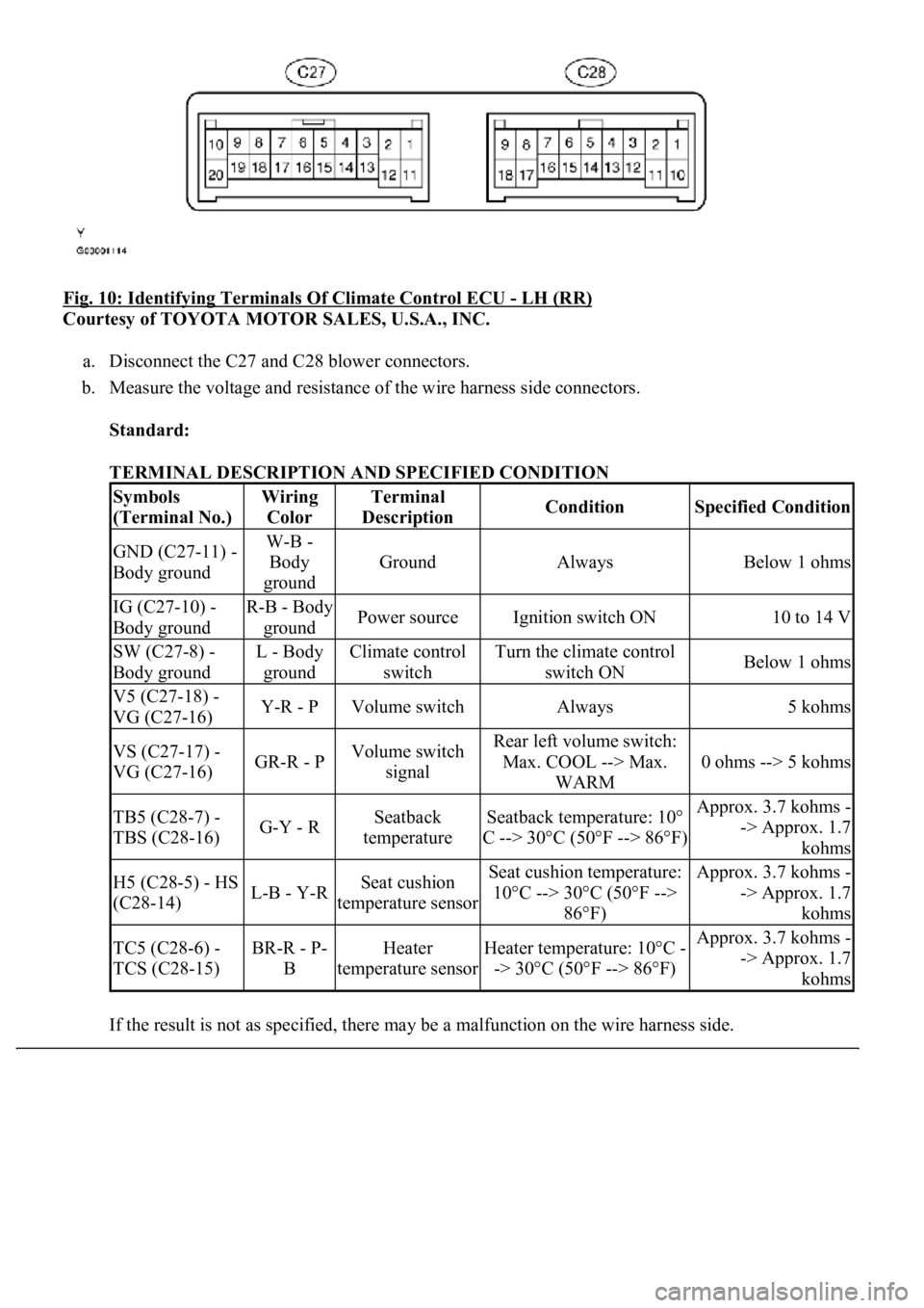
Fig. 10: Identifying Terminals Of Climate Control ECU - LH (RR)
Courtesy of TOYOTA MOTOR SALES, U.S.A., INC.
a. Disconnect the C27 and C28 blower connectors.
b. Measure the voltage and resistance of the wire harness side connectors.
Standard:
TERMINAL DESCRIPTION AND SPECIFIED CONDITION
If the result is not as specified, there ma
y be a malfunction on the wire harness side.
Symbols
(Terminal No.)Wiring
ColorTerminal
DescriptionConditionSpecified Condition
GND (C27-11) -
Body groundW-B -
Body
ground
GroundAlwaysBelow 1 ohms
IG (C27-10) -
Body groundR-B - Body
groundPower sourceIgnition switch ON10 to 14 V
SW (C27-8) -
Body groundL - Body
groundClimate control
switchTurn the climate control
switch ONBelow 1 ohms
V5 (C27-18) -
VG (C27-16)Y-R - PVolume switchAlways5 kohms
VS (C27-17) -
VG (C27-16)GR-R - PVolume switch
signalRear left volume switch:
Max. COOL --> Max.
WARM
0 ohms --> 5 kohms
TB5 (C28-7) -
TBS (C28-16)G-Y - RSeatback
temperatureSeatback temperature: 10°
C --> 30°C (50°F --> 86°F)Approx. 3.7 kohms -
-> Approx. 1.7
kohms
H5 (C28-5) - HS
(C28-14)L-B - Y-RSeat cushion
temperature sensorSeat cushion temperature:
10°C --> 30°C (50°F -->
86°F)Approx. 3.7 kohms -
-> Approx. 1.7
kohms
TC5 (C28-6) -
TCS (C28-15)BR-R - P-
BHeater
temperature sensorHeater temperature: 10°C -
-> 30°C (50°F --> 86°F)Approx. 3.7 kohms -
-> Approx. 1.7
kohms
Page 1601 of 4500
HINT:
*: For vehicles with a front seat climate control system
If the result is not as specified, the ECU may have a malfunction.
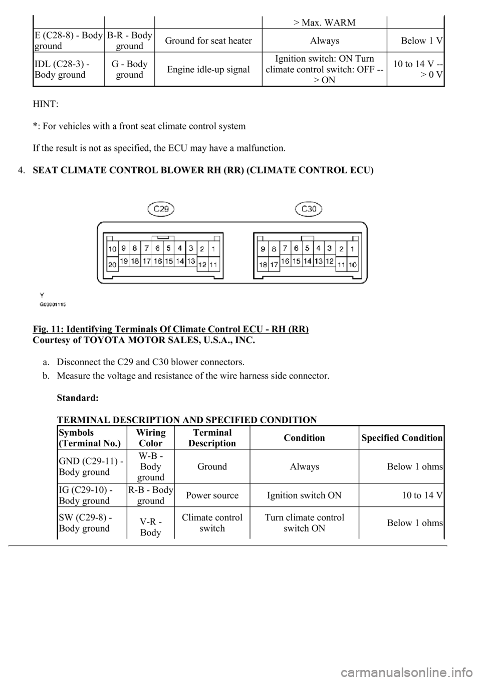
4.SEAT CLIMATE CONTROL BLOWER RH (RR) (CLIMATE CONTROL ECU)
Fig. 11: Identifying Terminals Of Climate Control ECU
- RH (RR)
Courtesy of TOYOTA MOTOR SALES, U.S.A., INC.
a. Disconnect the C29 and C30 blower connectors.
b. Measure the voltage and resistance of the wire harness side connector.
Standard:
TERMINAL DESCRIPTION AND SPECIFIED CONDITION
> Max. WARM
E (C28-8) - Body
groundB-R - Body
groundGround for seat heaterAlwaysBelow 1 V
IDL (C28-3) -
Body groundG - Body
groundEngine idle-up signal
Ignition switch: ON Turn
climate control switch: OFF --
> ON10 to 14 V --
> 0 V
Symbols
(Terminal No.)Wiring
ColorTerminal
DescriptionConditionSpecified Condition
GND (C29-11) -
Body groundW-B -
Body
ground
GroundAlwaysBelow 1 ohms
IG (C29-10) -
Body groundR-B - Body
groundPower sourceIgnition switch ON10 to 14 V
SW (C29-8) -
Body groundV-R -
Body Climate control
switchTurn climate control
switch ONBelow 1 ohms
Page 1602 of 4500
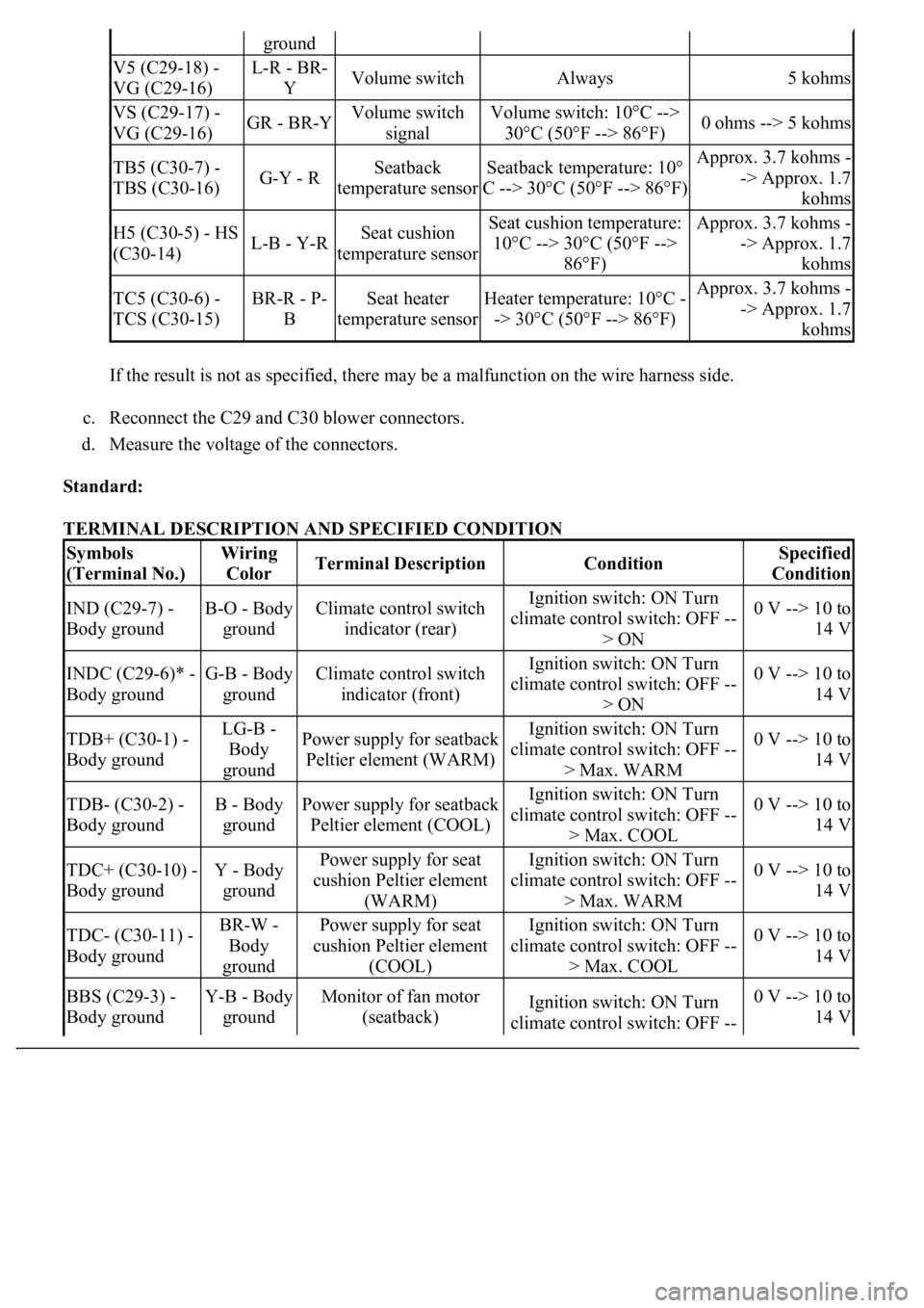
If the result is not as specified, there may be a malfunction on the wire harness side.
c. Reconnect the C29 and C30 blower connectors.
d. Measure the voltage of the connectors.
Standard:
TERMINAL DESCRIPTION AND SPECIFIED CONDITION
ground
V5 (C29-18) -
VG (C29-16)L-R - BR-
YVolume switchAlways5 kohms
VS (C29-17) -
VG (C29-16)GR - BR-YVolume switch
signalVolume switch: 10°C -->
30°C (50°F --> 86°F)0 ohms --> 5 kohms
TB5 (C30-7) -
TBS (C30-16)G-Y - RSeatback
temperature sensorSeatback temperature: 10°
C --> 30°C (50°F --> 86°F)Approx. 3.7 kohms -
-> Approx. 1.7
kohms
H5 (C30-5) - HS
(C30-14)L-B - Y-RSeat cushion
temperature sensorSeat cushion temperature:
10°C --> 30°C (50°F -->
86°F)Approx. 3.7 kohms -
-> Approx. 1.7
kohms
TC5 (C30-6) -
TCS (C30-15)BR-R - P-
BSeat heater
temperature sensorHeater temperature: 10°C -
-> 30°C (50°F --> 86°F)Approx. 3.7 kohms -
-> Approx. 1.7
kohms
Symbols
(Terminal No.)Wiring
ColorTerminal DescriptionConditionSpecified
Condition
IND (C29-7) -
Body groundB-O - Body
groundClimate control switch
indicator (rear)Ignition switch: ON Turn
climate control switch: OFF --
> ON0 V --> 10 to
14 V
INDC (C29-6)* -
Body groundG-B - Body
groundClimate control switch
indicator (front)Ignition switch: ON Turn
climate control switch: OFF --
> ON0 V --> 10 to
14 V
TDB+ (C30-1) -
Body groundLG-B -
Body
groundPower supply for seatback
Peltier element (WARM)Ignition switch: ON Turn
climate control switch: OFF --
> Max. WARM0 V --> 10 to
14 V
TDB- (C30-2) -
Body groundB - Body
groundPower supply for seatback
Peltier element (COOL)Ignition switch: ON Turn
climate control switch: OFF --
> Max. COOL0 V --> 10 to
14 V
TDC+ (C30-10) -
Body groundY - Body
groundPower supply for seat
cushion Peltier element
(WARM)Ignition switch: ON Turn
climate control switch: OFF --
> Max. WARM0 V --> 10 to
14 V
TDC- (C30-11) -
Body groundBR-W -
Body
groundPower supply for seat
cushion Peltier element
(COOL)Ignition switch: ON Turn
climate control switch: OFF --
> Max. COOL0 V --> 10 to
14 V
BBS (C29-3) -
Body groundY-B - Body
groundMonitor of fan motor
(seatback)Ignition switch: ON Turn
climate control switch: OFF --0 V --> 10 to
14 V