Page 12 of 4500

Fig. 8: ABS & TRACTION Actuator - Vehicle Stability Control
Courtesy of TOYOTA MOTOR SALES, U.S.A., INC.
Operation description
The skid control ECU determines vehicle condition by receiving signals from the speed sensor, yaw rate
and deceleration sensor and steering angle sensor. The skid control ECU controls engine torque with the
ECM, vehicle position with suspension control ECU via CAN communication, and oil pressure with the
pump and solenoid valve. The warning light comes on and the buzzer sounds when the system is
operating.
2.ABS with EBD & BA & TRAC & VSC OPERATION
a. Skid control ECU calculates vehicle stability tendency based on the signal of sensors, speed sensor,
yaw rate and deceleration sensor and steering angle sensor. And it judges whether the control of
engine output torque by electronic control throttle and of wheel brake pressure by brake actuator
will operate or not by the calculation results.
b. The SLIP indicator blinks and the VSC buzzer sounds to inform the driver that the VSC system is
operating. The SLIP indicator also blinks when TRAC is operating, and the operation being
performed is displayed.
3.FAIL SAFE FUNCTION
a. When a failure occurs in the ABS with BA & TRAC & VSC systems, the ABS warning light and
the VSC warning light turns on and the ABS with BA & TRAC & VSC operations are prohibited.
In addition to this, when there is a failure that disables the EBD operation, the brake warning light
also comes on and the EBD operation is prohibited (see FAIL
-SAFE CHART ).
b. If some control is prohibited due to a malfunction during it's operation, that control will be cut off
gradually not to change stability of vehicle suddenly.
4.PRE-COLLISION BRAKE ASSIST SYSTEM (w/ PRE-COLLISION BRAKE ASSIST SYSTEM)
Page 705 of 4500

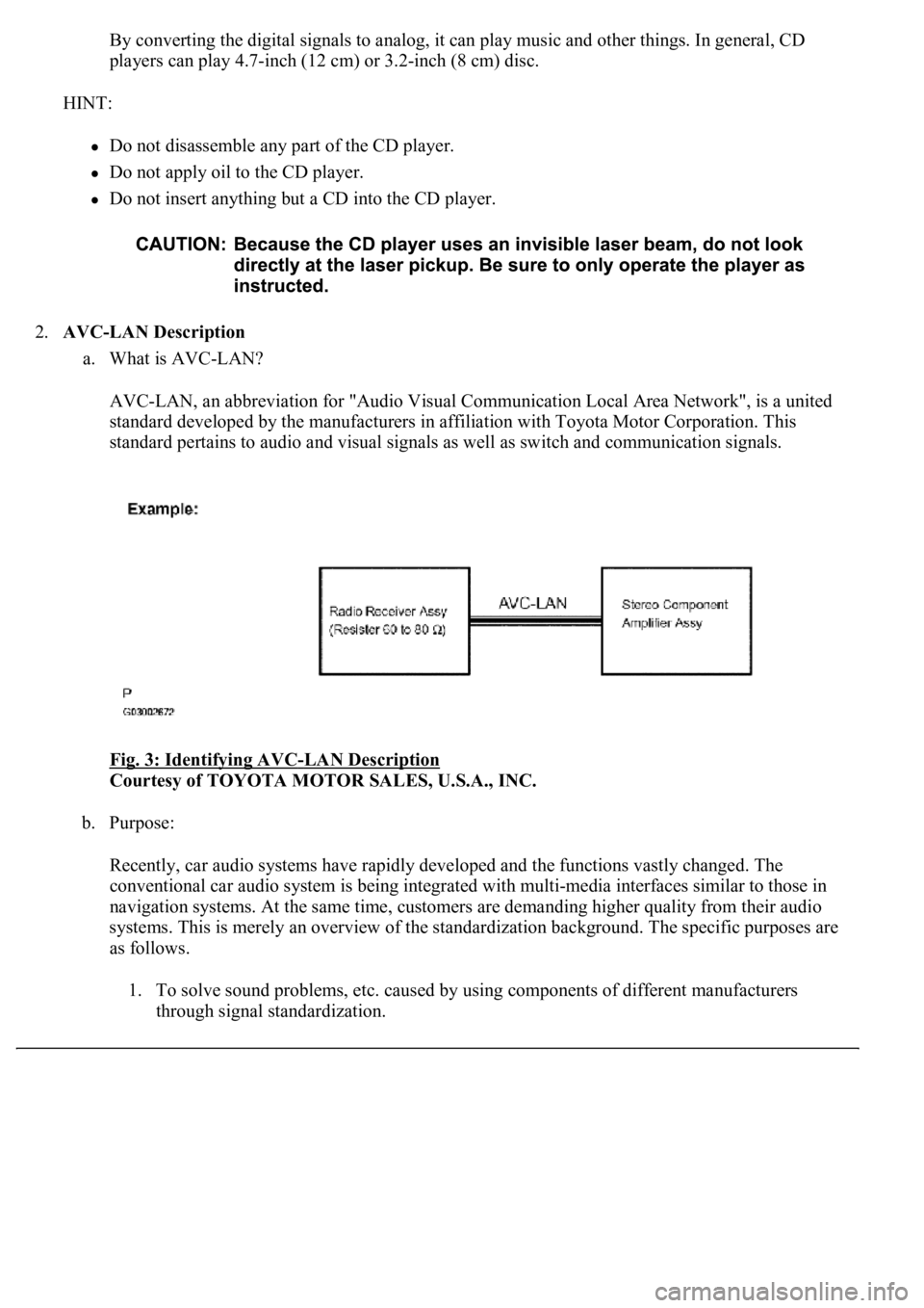
By converting the digital signals to analog, it can play music and other things. In general, CD
players can play 4.7-inch (12 cm) or 3.2-inch (8 cm) disc.
HINT:
Do not disassemble any part of the CD player.
Do not apply oil to the CD player.
Do not insert anything but a CD into the CD player.
2.AVC-LAN Description
a. What is AVC-LAN?
AVC-LAN, an abbreviation for "Audio Visual Communication Local Area Network", is a united
standard developed by the manufacturers in affiliation with Toyota Motor Corporation. This
standard pertains to audio and visual signals as well as switch and communication signals.
Fig. 3: Identifying AVC
-LAN Description
Courtesy of TOYOTA MOTOR SALES, U.S.A., INC.
b. Purpose:
Recently, car audio systems have rapidly developed and the functions vastly changed. The
conventional car audio system is being integrated with multi-media interfaces similar to those in
navigation systems. At the same time, customers are demanding higher quality from their audio
systems. This is merely an overview of the standardization background. The specific purposes are
as follows.
1. To solve sound problems, etc. caused by using components of different manufacturers
through signal standardization.
Page 1983 of 4500
Courtesy of TOYOTA MOTOR SALES, U.S.A., INC.
HINT:
If the value does not change to 0°, it is possible that the sensor is aiming at something
different. Reconfirm that there are no reflective materials in the surroundings.
3. Cover the sensor's right half with metal that can block radio wave (such as aluminum foil) in
order to reset the driving learning values (approximately 10 seconds).
Fig. 38: Covering Sensor With Metal
Courtesy of TOYOTA MOTOR SALES, U.S.A., INC.
HINT:
When the reset is completed, the buzzer sounds for 10 seconds.
Page 2046 of 4500

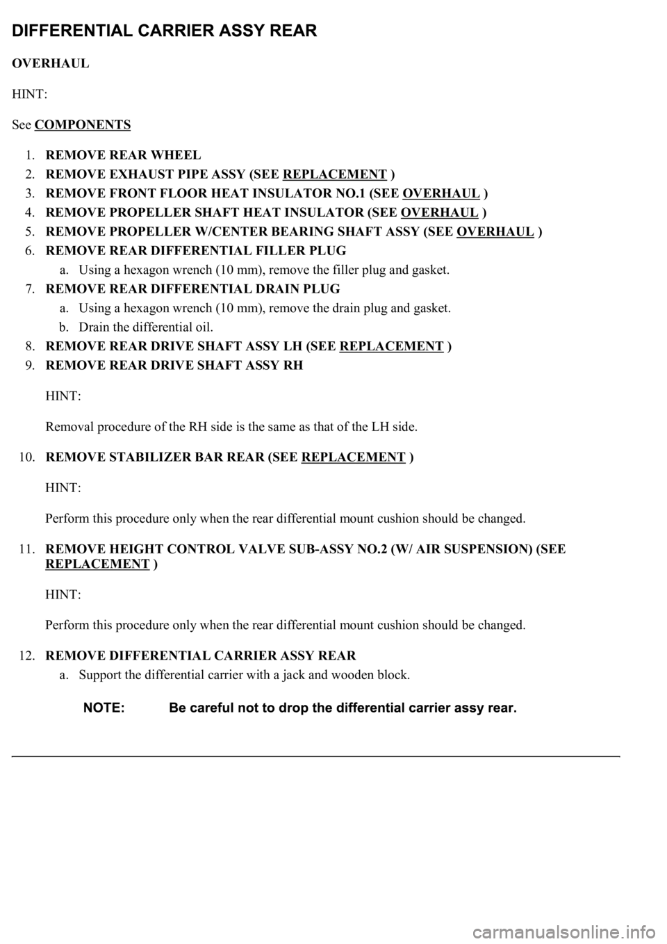
OVERHAUL
HINT:
See COMPONENTS
1.REMOVE REAR WHEEL
2.REMOVE EXHAUST PIPE ASSY (SEE REPLACEMENT
)
3.REMOVE FRONT FLOOR HEAT INSULATOR NO.1 (SEE OVERHAUL
)
4.REMOVE PROPELLER SHAFT HEAT INSULATOR (SEE OVERHAUL
)
5.REMOVE PROPELLER W/CENTER BEARING SHAFT ASSY (SEE OVERHAUL
)
6.REMOVE REAR DIFFERENTIAL FILLER PLUG
a. Using a hexagon wrench (10 mm), remove the filler plug and gasket.
7.REMOVE REAR DIFFERENTIAL DRAIN PLUG
a. Using a hexagon wrench (10 mm), remove the drain plug and gasket.
b. Drain the differential oil.
8.REMOVE REAR DRIVE SHAFT ASSY LH (SEE REPLACEMENT
)
9.REMOVE REAR DRIVE SHAFT ASSY RH
HINT:
Removal procedure of the RH side is the same as that of the LH side.
10.REMOVE STABILIZER BAR REAR (SEE REPLACEMENT
)
HINT:
Perform this procedure only when the rear differential mount cushion should be changed.
11.REMOVE HEIGHT CONTROL VALVE SUB-ASSY NO.2 (W/ AIR SUSPENSION) (SEE
REPLACEMENT
)
HINT:
Perform this procedure only when the rear differential mount cushion should be changed.
12.REMOVE DIFFERENTIAL CARRIER ASSY REAR
a. Support the differential carrier with a jack and wooden block.
Page 2740 of 4500
Fig. 57: ECM Connector Terminals Reference Chart
Courtesy of TOYOTA MOTOR SALES, U.S.A., INC.
NG: REPAIR OR REPLACE HARNESS OR CONNECTOR (SeeELECTRONIC CIRCUIT
INSPECTION PROCEDURE )
OK: REPLACE ECM (See REPLACEMENT
)
DTC P0710, P0712, P0713: TRANSMISSION FLUID TEMPERATURE SENSOR "A" CIRCUIT
LOW/HIGH INPUT
CIRCUIT DESCRIPTION
The ATF (Automatic Transmission Fluid) temperature sensor converts the fluid temperature into a resistance
value which is input into the ECM.
The ECM applies a voltage to the temperature sensor through ECM terminal OIL.
The sensor resistance changes with the transmission fluid temperature. As the temperature becomes higher, the
sensor resistance decreases.
One terminal of the sensor is grounded so that the sensor resistance decreases and the voltage goes down as the
temperature becomes higher.
The ECM calculates the fluid temperature based on the volta
ge signal.
Page 2765 of 4500

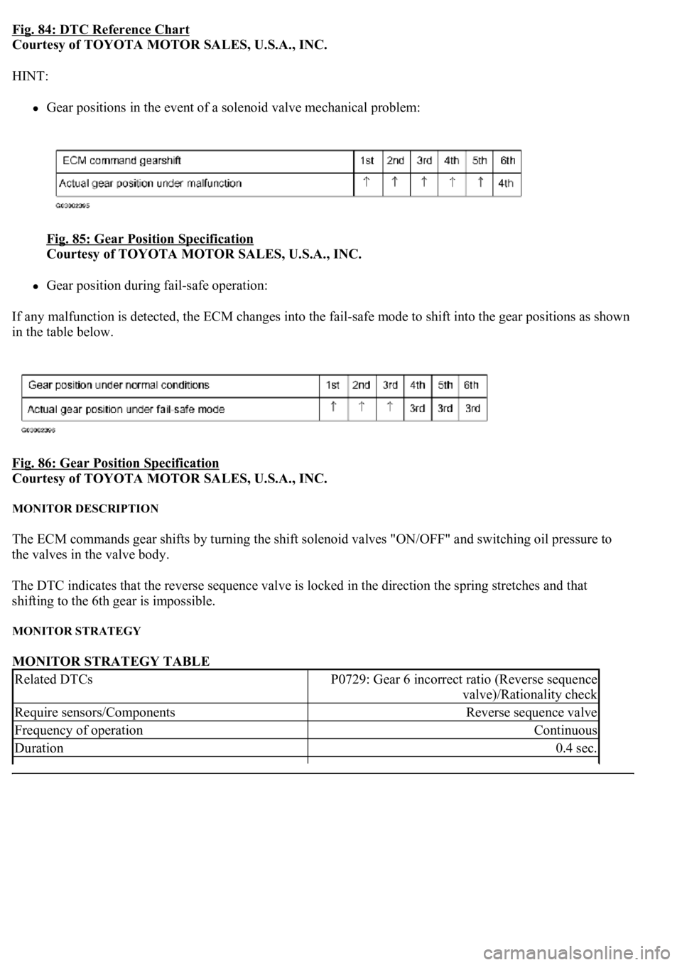
Fig. 84: DTC Reference Chart
Courtesy of TOYOTA MOTOR SALES, U.S.A., INC.
HINT:
Gear positions in the event of a solenoid valve mechanical problem:
Fig. 85: Gear Position Specification
Courtesy of TOYOTA MOTOR SALES, U.S.A., INC.
Gear position during fail-safe operation:
If any malfunction is detected, the ECM changes into the fail-safe mode to shift into the gear positions as shown
in the table below.
Fig. 86: Gear Position Specification
Courtesy of TOYOTA MOTOR SALES, U.S.A., INC.
MONITOR DESCRIPTION
The ECM commands gear shifts by turning the shift solenoid valves "ON/OFF" and switching oil pressure to
the valves in the valve body.
The DTC indicates that the reverse sequence valve is locked in the direction the spring stretches and that
shifting to the 6th gear is impossible.
MONITOR STRATEGY
MONITOR STRATEGY TABLE
Related DTCsP0729: Gear 6 incorrect ratio (Reverse sequence
valve)/Rationality check
Require sensors/ComponentsReverse sequence valve
Frequency of operationContinuous
Duration0.4 sec.