2003 LEXUS LS430 alarm
[x] Cancel search: alarmPage 495 of 4500

Fig. 17: Diagnostic Trouble Code Information Chart (2 Of 2)
Courtesy of TOYOTA MOTOR SALES, U.S.A., INC.
*1: For codes in the "Indicator Light" column with a "circ" mark, the absorber control indicator lamp blinks at 1
second intervals.
*2: For codes in the "Indicator Light" column with a " (xcirc)" mark, when trouble occurs, "HEIGHT HI" is
displayed on the multi-information display. Also, the master warning light is lit on the combination meter and
an alarm sounds.
*3: Since the relief pressure of the compressed air is 980 kPa (10 kgf/cm
2 , 142 psi), if vehicle height control is
attempted on a steeply sloping road, when the vehicle is overloaded, or when the vehicle height is jacked up
with the engine running, code "C1751" may be output and vehicle height control may be suspended. (This is not
abnormal.) In this case, however, when detecting the first error, approximately 10 minutes after the ignition
switch was turned to the ON position, vehicle height control is resumed. When the following errors are
detected, it takes 70 minutes until the control is resumed.
*4: If vehicle height control is operated while the wheels are removed or the vehicle is jacked up, code "C1752"
may be output, but this is not abnormal. When code "C1752" is output, vehicle height control is not carried out.
However, control is resumed if the ignition switch is turned off, then to the ON position again.
CIRCUIT DESCRIPTION
The height control sensor sub-assy controls the resistance value by following changes in vehicle height. The
suspension control ECU detects the change in vehicle height from the transformed voltage. The suspension
control ECU outputs a constant voltage of 5 V to the SHB terminal of the height control sensor sub-assy.
In the height control sensor, the voltage is changed due to resistance. The changed voltage is output from the
Page 2467 of 4500
Courtesy of TOYOTA MOTOR SALES, U.S.A., INC.
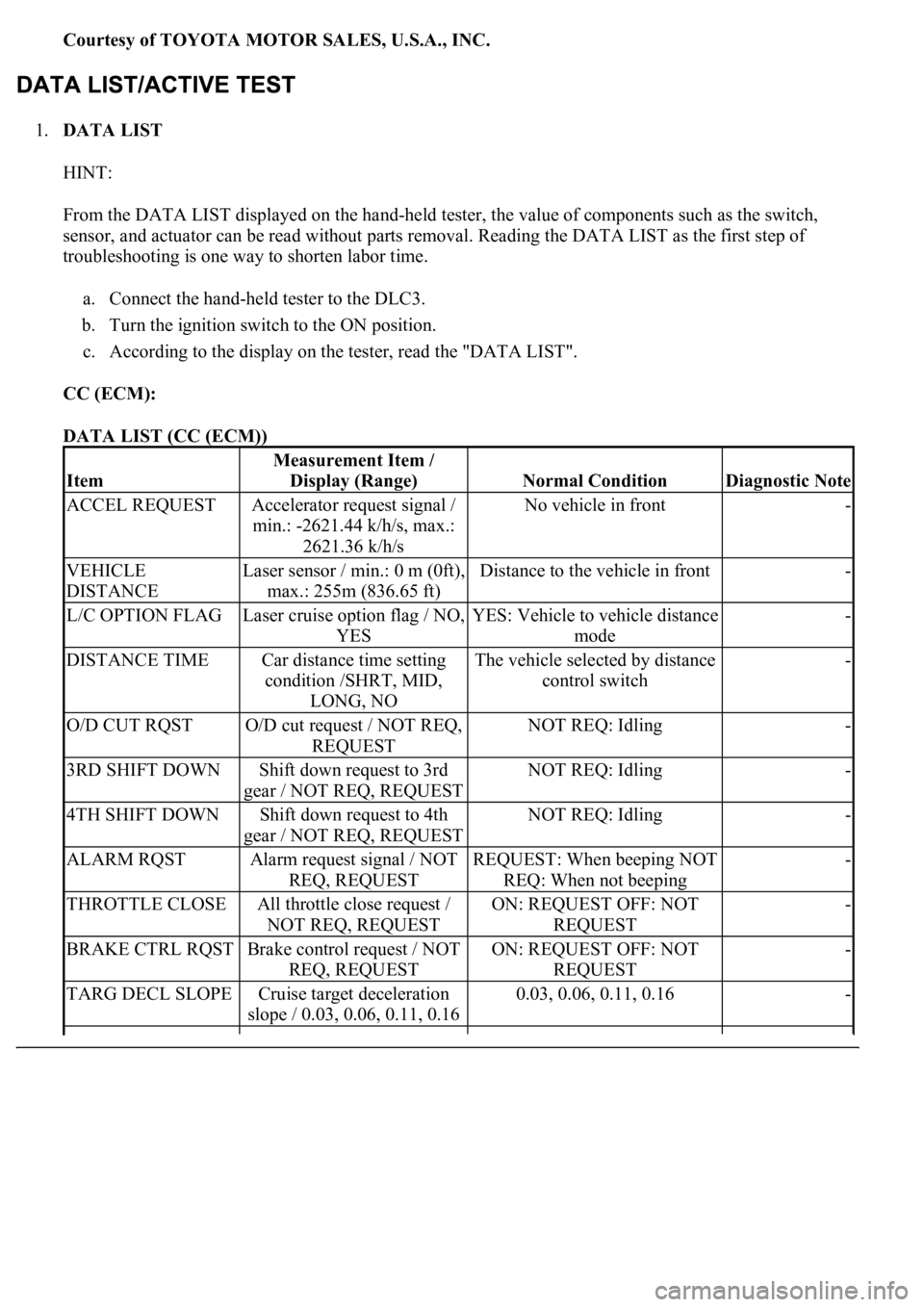
1.DATA LIST
HINT:
From the DATA LIST displayed on the hand-held tester, the value of components such as the switch,
sensor, and actuator can be read without parts removal. Reading the DATA LIST as the first step of
troubleshooting is one way to shorten labor time.
a. Connect the hand-held tester to the DLC3.
b. Turn the ignition switch to the ON position.
c. According to the display on the tester, read the "DATA LIST".
CC (ECM):
DATA LIST (CC (ECM))
Item
Measurement Item /
Display (Range)
Normal ConditionDiagnostic Note
ACCEL REQUESTAccelerator request signal /
min.: -2621.44 k/h/s, max.:
2621.36 k/h/sNo vehicle in front-
VEHICLE
DISTANCELaser sensor / min.: 0 m (0ft),
max.: 255m (836.65 ft)Distance to the vehicle in front-
L/C OPTION FLAGLaser cruise option flag / NO,
YESYES: Vehicle to vehicle distance
mode-
DISTANCE TIMECar distance time setting
condition /SHRT, MID,
LONG, NOThe vehicle selected by distance
control switch-
O/D CUT RQSTO/D cut request / NOT REQ,
REQUESTNOT REQ: Idling-
3RD SHIFT DOWNShift down request to 3rd
gear / NOT REQ, REQUESTNOT REQ: Idling-
4TH SHIFT DOWNShift down request to 4th
gear / NOT REQ, REQUESTNOT REQ: Idling-
ALARM RQSTAlarm request signal / NOT
REQ, REQUESTREQUEST: When beeping NOT
REQ: When not beeping-
THROTTLE CLOSEAll throttle close request /
NOT REQ, REQUESTON: REQUEST OFF: NOT
REQUEST-
BRAKE CTRL RQSTBrake control request / NOT
REQ, REQUESTON: REQUEST OFF: NOT
REQUEST-
TARG DECL SLOPECruise target deceleration
slope / 0.03, 0.06, 0.11, 0.160.03, 0.06, 0.11, 0.16-
Page 2486 of 4500
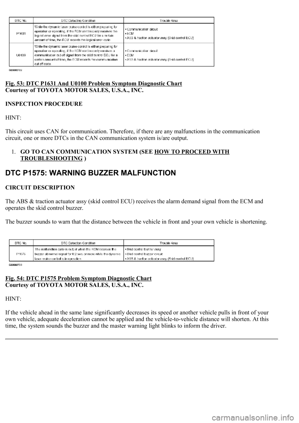
Fig. 53: DTC P1631 And U0100 Problem Symptom Diagnostic Chart
Courtesy of TOYOTA MOTOR SALES, U.S.A., INC.
INSPECTION PROCEDURE
HINT:
This circuit uses CAN for communication. Therefore, if there are any malfunctions in the communication
circuit, one or more DTCs in the CAN communication system is/are output.
1.GO TO CAN COMMUNICATION SYSTEM (SEE HOW TO PROCEED WITH
TROUBLESHOOTING )
CIRCUIT DESCRIPTION
The ABS & traction actuator assy (skid control ECU) receives the alarm demand signal from the ECM and
operates the skid control buzzer.
The buzzer sounds to warn that the distance between the vehicle in front and your own vehicle is shortening.
Fig. 54: DTC P1575 Problem Symptom Diagnostic
Chart
Courtesy of TOYOTA MOTOR SALES, U.S.A., INC.
HINT:
If the vehicle ahead in the same lane significantly decreases its speed or another vehicle pulls in front of your
own vehicle, adequate deceleration cannot be applied and the vehicle-to-vehicle distance will shorten. At this
time, the s
ystem sounds the buzzer and the master warning light blinks to inform the driver.
Page 2519 of 4500
CIRCUIT DESCRIPTION
When the cruise control main switch is on, CRUISE main indicator light and READY indicator light come on.
This indicates the control condition (presence or absence of a vehicle in front, vehicle-to-vehicle distance, and
set vehicle speed) and fail-safe state through the multiplex communication system and CAN communication
system.
The master warning light and, CRUISE main indicator light come on and vehicle-to-vehicle distance
information is displayed on the combination meter as the alarm buzzer sounds.
Items such as "Clean Radar Sensor", "Cruise not Available", "Check Cruise System" and "Radar Cruise Ready"
are displayed in the multi-information display on the combination meter when the ECM detects signals from
each sensor and actuator and sends them to the combination meter via CAN and BEAN.
HINT:
If the vehicle in front in the same lane significantly decreases vehicle speed or another vehicle pulls in front of
your vehicle, adequate deceleration cannot be applied and the vehicle-to-vehicle distance will shorten. At this
time, the system sounds the buzzer and the master warning light blinks to warn the driver.
Each indicator in the dynamic laser cruise control uses CAN and BEAN for communication. Therefore if there
are any malfunctions in this circuit, check for DTCs in the CAN communication and multiplex communication
systems.
INSPECTION PROCEDURE
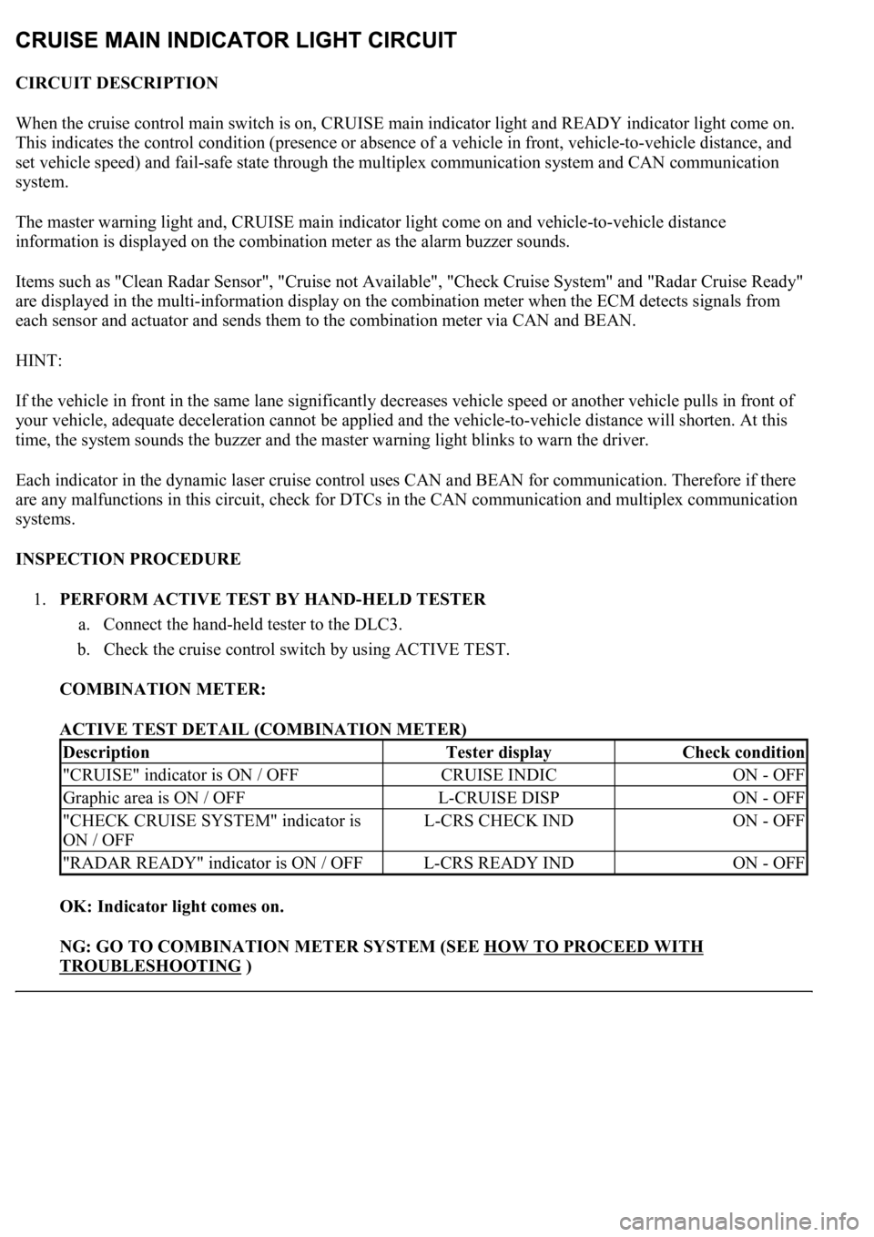
1.PERFORM ACTIVE TEST BY HAND-HELD TESTER
a. Connect the hand-held tester to the DLC3.
b. Check the cruise control switch by using ACTIVE TEST.
COMBINATION METER:
ACTIVE TEST DETAIL (COMBINATION METER)
OK: Indicator light comes on.
NG: GO TO COMBINATION METER SYSTEM (SEE HOW TO PROCEED WITH
TROUBLESHOOTING )
DescriptionTester displayCheck condition
"CRUISE" indicator is ON / OFFCRUISE INDICON - OFF
Graphic area is ON / OFFL-CRUISE DISPON - OFF
"CHECK CRUISE SYSTEM" indicator is
ON / OFFL-CRS CHECK INDON - OFF
"RADAR READY" indicator is ON / OFFL-CRS READY INDON - OFF
Page 2587 of 4500
CIRCUIT DESCRIPTION
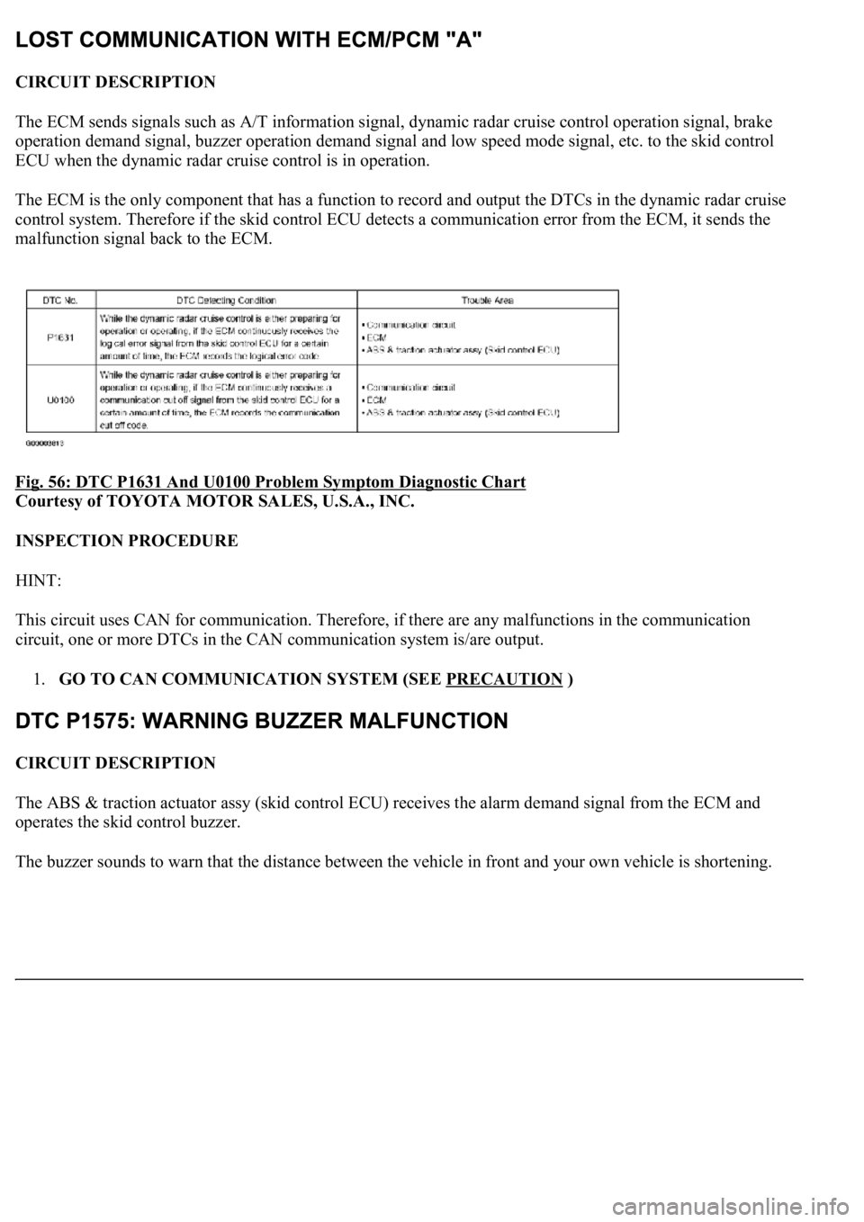
The ECM sends signals such as A/T information signal, dynamic radar cruise control operation signal, brake
operation demand signal, buzzer operation demand signal and low speed mode signal, etc. to the skid control
ECU when the dynamic radar cruise control is in operation.
<0037004b004800030028002600300003004c005600030057004b0048000300520051004f005c000300460052005000530052005100480051005700030057004b004400570003004b0044005600030044000300490058005100460057004c00520051000300
57005200030055004800460052005500470003004400510047[ output the DTCs in the dynamic radar cruise
control system. Therefore if the skid control ECU detects a communication error from the ECM, it sends the
malfunction signal back to the ECM.
Fig. 56: DTC P1631 And U0100 Problem Symptom Diagnostic Chart
Courtesy of TOYOTA MOTOR SALES, U.S.A., INC.
INSPECTION PROCEDURE
HINT:
This circuit uses CAN for communication. Therefore, if there are any malfunctions in the communication
circuit, one or more DTCs in the CAN communication system is/are output.
1.GO TO CAN COMMUNICATION SYSTEM (SEE PRECAUTION
)
CIRCUIT DESCRIPTION
The ABS & traction actuator assy (skid control ECU) receives the alarm demand signal from the ECM and
operates the skid control buzzer.
The buzzer sounds to warn that the distance between the vehicle in front and
your own vehicle is shortening.
Page 2620 of 4500
CIRCUIT DESCRIPTION
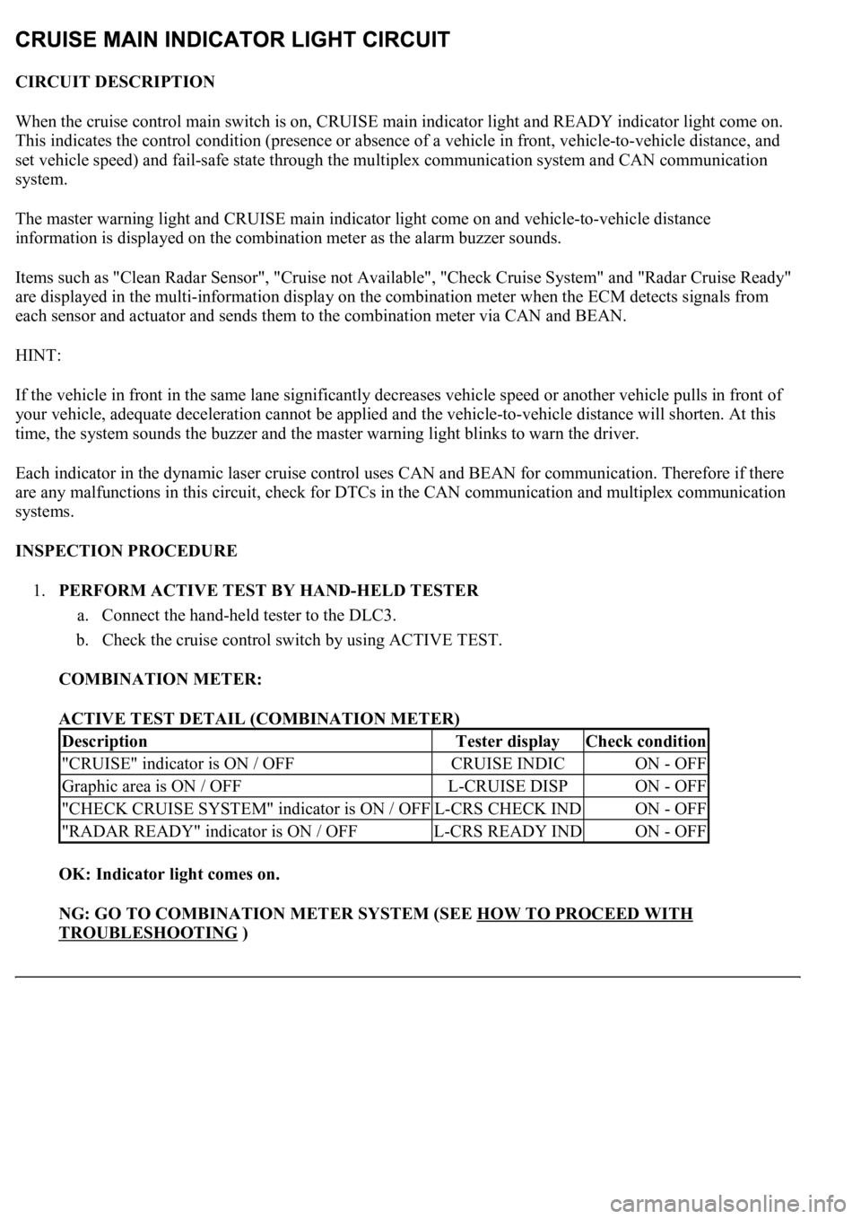
When the cruise control main switch is on, CRUISE main indicator light and READY indicator light come on.
This indicates the control condition (presence or absence of a vehicle in front, vehicle-to-vehicle distance, and
set vehicle speed) and fail-safe state through the multiplex communication system and CAN communication
system.
The master warning light and CRUISE main indicator light come on and vehicle-to-vehicle distance
information is displayed on the combination meter as the alarm buzzer sounds.
Items such as "Clean Radar Sensor", "Cruise not Available", "Check Cruise System" and "Radar Cruise Ready"
are displayed in the multi-information display on the combination meter when the ECM detects signals from
each sensor and actuator and sends them to the combination meter via CAN and BEAN.
HINT:
If the vehicle in front in the same lane significantly decreases vehicle speed or another vehicle pulls in front of
your vehicle, adequate deceleration cannot be applied and the vehicle-to-vehicle distance will shorten. At this
time, the system sounds the buzzer and the master warning light blinks to warn the driver.
Each indicator in the dynamic laser cruise control uses CAN and BEAN for communication. Therefore if there
are any malfunctions in this circuit, check for DTCs in the CAN communication and multiplex communication
systems.
INSPECTION PROCEDURE
1.PERFORM ACTIVE TEST BY HAND-HELD TESTER
a. Connect the hand-held tester to the DLC3.
b. Check the cruise control switch by using ACTIVE TEST.
COMBINATION METER:
ACTIVE TEST DETAIL (COMBINATION METER)
OK: Indicator light comes on.
NG: GO TO COMBINATION METER SYSTEM (SEE HOW TO PROCEED WITH
TROUBLESHOOTING )
DescriptionTester displayCheck condition
"CRUISE" indicator is ON / OFFCRUISE INDICON - OFF
Graphic area is ON / OFFL-CRUISE DISPON - OFF
"CHECK CRUISE SYSTEM" indicator is ON / OFFL-CRS CHECK INDON - OFF
"RADAR READY" indicator is ON / OFFL-CRS READY INDON - OFF