Page 13 of 4500
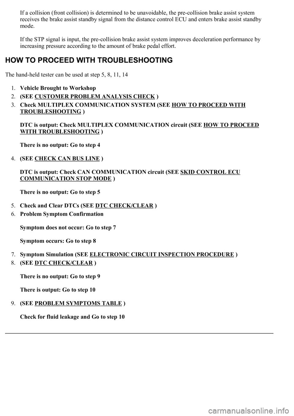
If a collision (front collision) is determined to be unavoidable, the pre-collision brake assist system
receives the brake assist standby signal from the distance control ECU and enters brake assist standby
mode.
If the STP signal is input, the pre-collision brake assist system improves deceleration performance by
increasing pressure according to the amount of brake pedal effort.
The hand-held tester can be used at step 5, 8, 11, 14
1.Vehicle Brought to Workshop
2.(SEE CUSTOMER PROBLEM ANALYSIS CHECK
)
3.Check MULTIPLEX COMMUNICATION SYSTEM (SEE HOW TO PROCEED WITH
TROUBLESHOOTING )
DTC is output: Check MULTIPLEX COMMUNICATION circuit (SEE HOW TO PROCEED
WITH TROUBLESHOOTING )
There is no output: Go to step 4
4.(SEE CHECK CAN BUS LINE
)
DTC is output: Check CAN COMMUNICATION circuit (SEE SKID CONTROL ECU
COMMUNICATION STOP MODE )
There is no output: Go to step 5
5.Check and Clear DTCs (SEE DTC CHECK/CLEAR
)
6.Problem Symptom Confirmation
Symptom does not occur: Go to step 7
Symptom occurs: Go to step 8
7.Symptom Simulation (SEE ELECTRONIC CIRCUIT INSPECTION PROCEDURE
)
8.(SEE DTC CHECK/CLEAR
)
There is no output: Go to step 9
There is output: Go to step 10
9.(SEE PROBLEM SYMPTOMS TABLE
)
Check for fluid leakage and Go to step 10
Page 39 of 4500
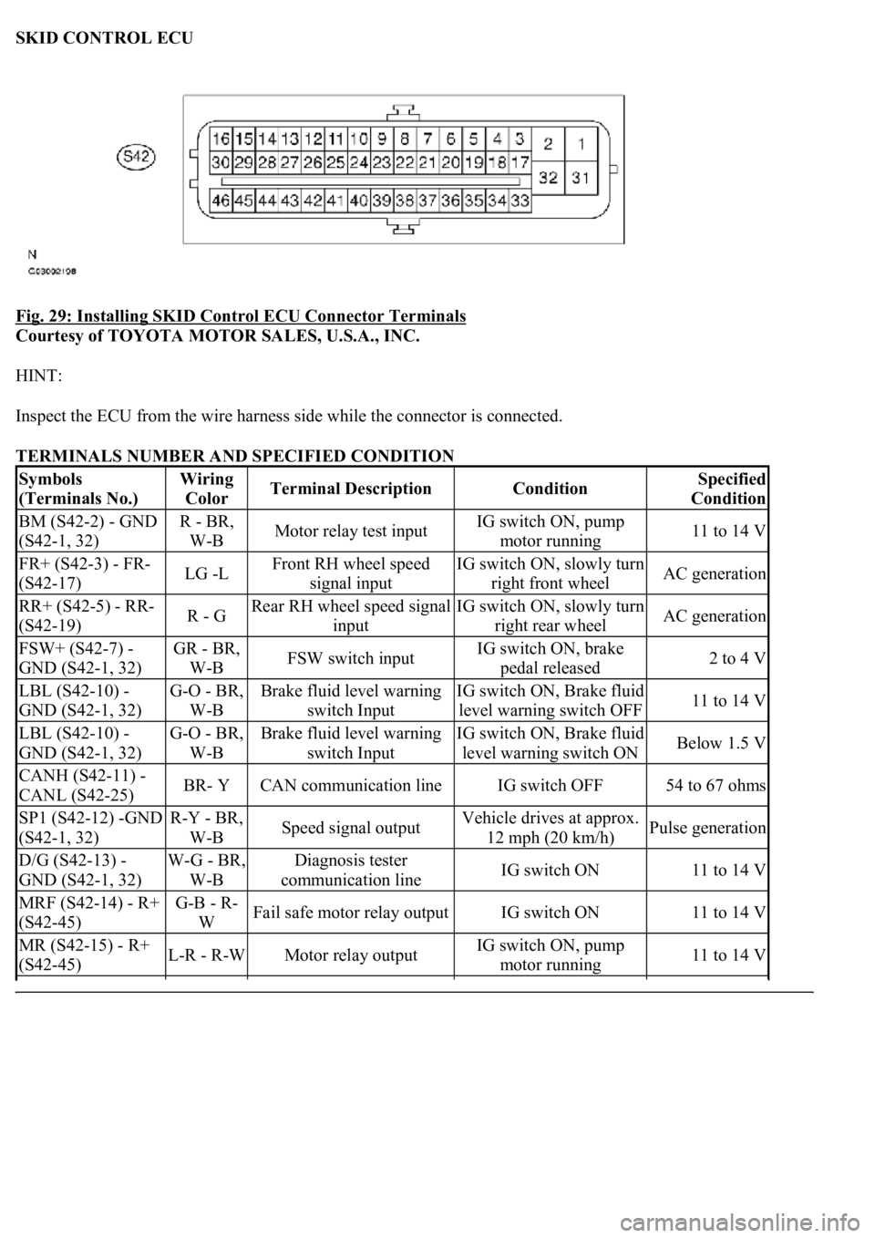
SKID CONTROL ECU
Fig. 29: Installing SKID Control ECU Connector Terminals
Courtesy of TOYOTA MOTOR SALES, U.S.A., INC.
HINT:
Inspect the ECU from the wire harness side while the connector is connected.
TERMINALS NUMBER AND SPECIFIED CONDITION
Symbols
(Terminals No.)Wiring
ColorTerminal DescriptionConditionSpecified
Condition
BM (S42-2) - GND
(S42-1, 32)R - BR,
W-BMotor relay test inputIG switch ON, pump
motor running11 to 14 V
FR+ (S42-3) - FR-
(S42-17)LG -LFront RH wheel speed
signal inputIG switch ON, slowly turn
right front wheelAC generation
RR+ (S42-5) - RR-
(S42-19)R - GRear RH wheel speed signal
inputIG switch ON, slowly turn
right rear wheelAC generation
FSW+ (S42-7) -
GND (S42-1, 32)GR - BR,
W-BFSW switch inputIG switch ON, brake
pedal released2 to 4 V
LBL (S42-10) -
GND (S42-1, 32)G-O - BR,
W-BBrake fluid level warning
switch InputIG switch ON, Brake fluid
level warning switch OFF11 to 14 V
LBL (S42-10) -
GND (S42-1, 32)G-O - BR,
W-BBrake fluid level warning
switch InputIG switch ON, Brake fluid
level warning switch ONBelow 1.5 V
CANH (S42-11) -
CANL (S42-25)BR- YCAN communication lineIG switch OFF54 to 67 ohms
SP1 (S42-12) -GND
(S42-1, 32)R-Y - BR,
W-BSpeed signal outputVehicle drives at approx.
12 mph (20 km/h)Pulse generation
D/G (S42-13) -
GND (S42-1, 32)W-G - BR,
W-BDiagnosis tester
communication lineIG switch ON11 to 14 V
MRF (S42-14) - R+
(S42-45)G-B - R-
WFail safe motor relay outputIG switch ON11 to 14 V
MR (S42-15) - R+
(S42-45)L-R - R-WMotor relay outputIG switch ON, pump
motor running11 to 14 V
Page 128 of 4500

c. Select the DATA LIST mode on the hand-held tester.
MEASUREMENT ITEM / RANGE (DISPLAY) DESCRIPTION
d. Check that the brake fluid pressure value of the master cylinder pressure sensor observed in the
hand held tester changes when the brake pedal is depressed.
OK: Go to next step
When the pedal is depressed, displayed voltage on the hand-held tester increases.
NG: Go to step 2
OK: REPLACE ABS & TRACTION ACTUATOR ASSY (SEE REPLACEMENT
)
2.INSPECT SKID CONTROL ECU TERMINAL VOLTAGE (STP TERMINAL)
a. Disconnect the skid control ECU connector.
b. Measure the voltage according to the value (s) in the table below.
Standard:
TESTER CONNECTION SPECIFIED CONDITION
NG: CHECK AND REPLACE STOP LIGHT SWITCH CIRCUIT
OK: REPLACE ABS & TRACTION ACTUATOR ASSY (SEE REPLACEMENT
)
ItemMeasurement Item / Range (Display)Normal Condition
MAS CYL PRS
1Master cylinder pressure sensor 1 reading /
min.: 0 V, max.: 5 VWhen brake pedal is released:
0.3 to 0.9V
Tester ConnectionSwitch ConditionSpecified Condition
S42-27 (STP) - Body groundBrake pedal depressed8 to 14V
S42-27 (STP) - Body groundBrake pedal releasedBelow 1 V
Page 162 of 4500
CIRCUIT DESCRIPTION
The BRAKE warning light comes on when the brake fluid is insufficient, the parking brake is applied or the
EBD is defective.
The skid control ECU is connected to the combination meter via CAN and Multiplex communications.
The pad wear indicator is installed to the brake pad (right side).
If the wear indicator wire is open, "Brake Wear" appears on the multi-information display, which indicates that
the pad must be replaced.
WIRING DIAGRAM
Page 165 of 4500
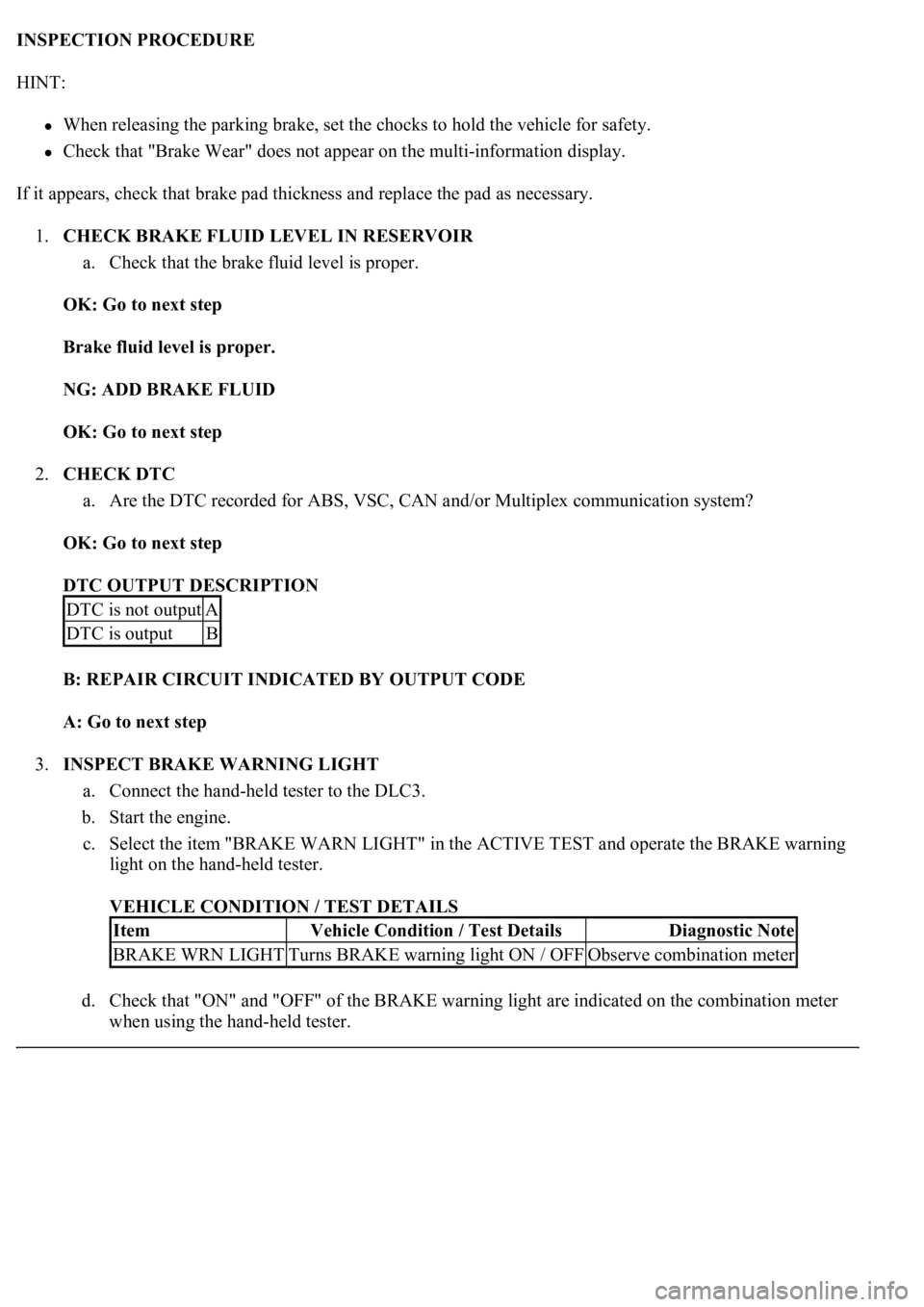
INSPECTION PROCEDURE
HINT:
When releasing the parking brake, set the chocks to hold the vehicle for safety.
Check that "Brake Wear" does not appear on the multi-information display.
If it appears, check that brake pad thickness and replace the pad as necessary.
1.CHECK BRAKE FLUID LEVEL IN RESERVOIR
a. Check that the brake fluid level is proper.
OK: Go to next step
Brake fluid level is proper.
NG: ADD BRAKE FLUID
OK: Go to next step
2.CHECK DTC
a. Are the DTC recorded for ABS, VSC, CAN and/or Multiplex communication system?
OK: Go to next step
DTC OUTPUT DESCRIPTION
B: REPAIR CIRCUIT INDICATED BY OUTPUT CODE
A: Go to next step
3.INSPECT BRAKE WARNING LIGHT
a. Connect the hand-held tester to the DLC3.
b. Start the engine.
c. Select the item "BRAKE WARN LIGHT" in the ACTIVE TEST and operate the BRAKE warning
light on the hand-held tester.
VEHICLE CONDITION / TEST DETAILS
d. Check that "ON" and "OFF" of the BRAKE warning light are indicated on the combination meter
when usin
g the hand-held tester.
DTC is not outputA
DTC is outputB
ItemVehicle Condition / Test DetailsDiagnostic Note
BRAKE WRN LIGHTTurns BRAKE warning light ON / OFFObserve combination meter
Page 168 of 4500
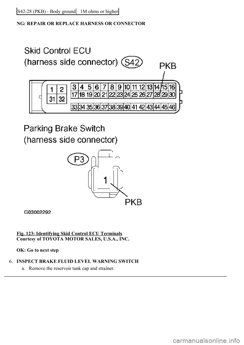
NG: REPAIR OR REPLACE HARNESS OR CONNECTOR
Fig. 123: Identifying Skid Control ECU Terminals
Courtesy of TOYOTA MOTOR SALES, U.S.A., INC.
OK: Go to next step
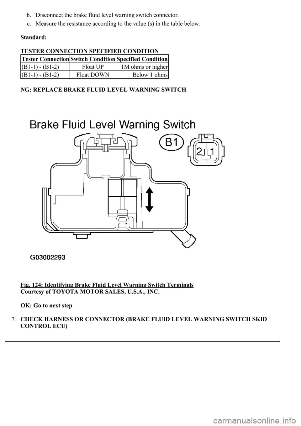
6.INSPECT BRAKE FLUID LEVEL WARNING SWITCH
a. Remove the reservoir tank cap and strainer.
S42-28 (PKB) - Body ground1M ohms or higher
Page 169 of 4500
b. Disconnect the brake fluid level warning switch connector.
c. Measure the resistance according to the value (s) in the table below.
Standard:
TESTER CONNECTION SPECIFIED CONDITION
NG: REPLACE BRAKE FLUID LEVEL WARNING SWITCH
Fig. 124: Identifying Brake Fluid Level Warning Switch Terminals
Courtesy of TOYOTA MOTOR SALES, U.S.A., INC.
OK: Go to next step
7.CHECK HARNESS OR CONNECTOR (BRAKE FLUID LEVEL WARNING SWITCH SKID
CONTROL ECU)
Tester ConnectionSwitch ConditionSpecified Condition
(B1-1) - (B1-2)Float UP1M ohms or higher
(B1-1) - (B1-2)Float DOWNBelow 1 ohms
Page 170 of 4500
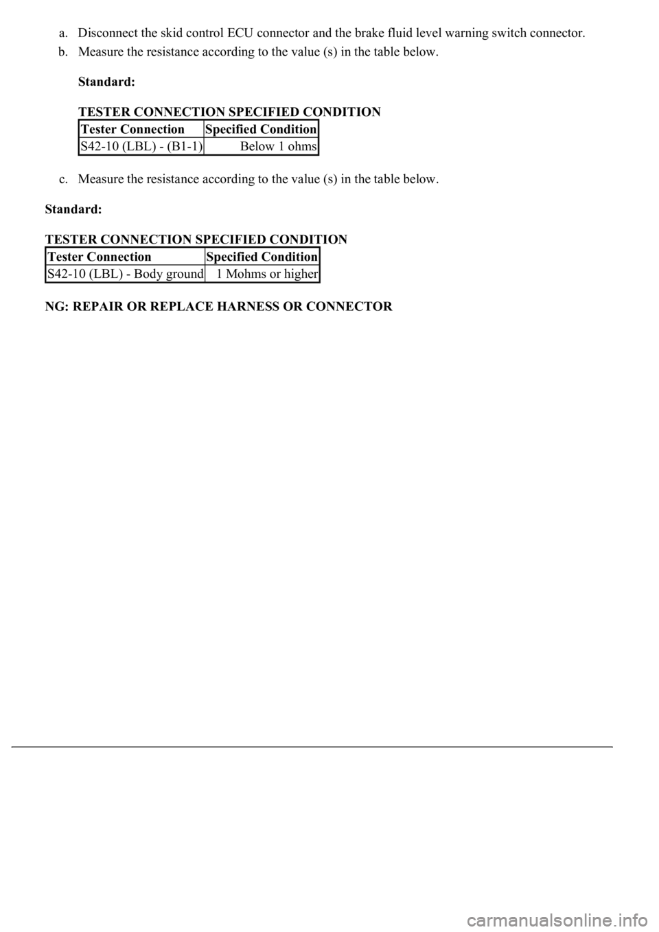
a. Disconnect the skid control ECU connector and the brake fluid level warning switch connector.
b. Measure the resistance according to the value (s) in the table below.
Standard:
TESTER CONNECTION SPECIFIED CONDITION
c. Measure the resistance according to the value (s) in the table below.
Standard:
TESTER CONNECTION SPECIFIED CONDITION
NG: REPAIR OR REPLACE HARNESS OR CONNECTOR
Tester ConnectionSpecified Condition
S42-10 (LBL) - (B1-1)Below 1 ohms
Tester ConnectionSpecified Condition
S42-10 (LBL) - Body ground1 Mohms or higher