Page 1199 of 4500

conventional communication line (SIL).
1.BRIEF DESCRIPTION
a. The CAN (Controller Area Network) is a serial data communication system for real time
application. It is a multiplex communication system equipped for a vehicle and has a high
communication speed (500 kbps) and the function to detect malfunctions.
b. By pairing the CANH and CANL bus lines, the CAN performs communication based on
differential voltage.
c. Many ECUs (sensors) installed on the vehicle operate by sharing information and communicating
with each other.
d. The CAN has two resistors of 120 ohms which are necessary to communicate with the main bus
line.
2.DEFINITION OF TERMS
a. Main bus line
1. The main bus line is the wire harness between the two terminus circuits on the bus
(communication line). This is the main bus in the CAN communication system.
b. Sub bus line
1. The sub bus line is the wire harness which diverges from the main bus line to the ECU or
sensor.
c. Terminus circuit
1. The terminus circuit is a circuit which is placed to convert communication current of the
CAN communication into bus voltage. It consists of a resistor and condenser. Two terminus
circuits are necessary on a bus.
d. CAN J/C
1. The CAN J/C is a junction designed for CAN communication, which stores a terminus
circuit.
3.ECUs OR SENSORS WHICH COMMUNICATE THROUGH CAN COMMUNICATION
SYSTEM
a. Skid Control ECU with Actuator
b. Yaw Rate Sensor
c. Steering Sensor
d. Television Camera ECU
e. Seat Belt Control ECU
f. Distance Control ECU
g. Suspension Control ECU
h. ECM
i. Gateway ECU
4.DIAGNOSTIC CODE FOR CAN COMMUNICATION SYSTEM
a. DTCs for the CAN communication system are as follows:
Page 2040 of 4500
Fig. 2: Identifying Differential Components (1 Of 2)
Courtesy of TOYOTA MOTOR SALES, U.S.A., INC.
Page 2041 of 4500
Fig. 3: Identifying Differential Components (2 Of 2)
Courtesy of TOYOTA MOTOR SALES, U.S.A., INC.
ADJUSTMENT
1.INSPECT AND ADJUST DIFFERENTIAL OIL
Page 2042 of 4500
a. Stop the vehicle on a level place.
b. Using a hexagon wrench (10 mm), remove the rear differential filler plug and gasket.
c. Check that the oil surface is within 5 mm (0.20 in.) of the lowest position of the inner surface of the
differential filler plug opening.
Fig. 4: Inspecting And Adjusting Differential Oil
Courtesy of TOYOTA MOTOR SALES, U.S.A., INC.
d. Check for oil leakage when the oil level is low.
e. Using a hexagon wrench (10 mm), install the rear differential filler plug with a new gasket.
Torque: 49 N.m (500 kgf.cm, 36 ft.lbf)
2.ADD DIFFERENTIAL OIL
a. Using a hexagon wrench (10 mm), remove the rear differential filler plug and gasket.
b. Add oil.
Oil type: Differential synthetic gear oil GL-5 75W-90 or equivalent
Capacity: 1.35 +/- 0.05 liters (1.43 +/- 0.05 US qts, 1.19 +/- 0.04 Imp. qts)
Page 2043 of 4500
c. Check the oil level.
d. Using a hexagon wrench (10 mm), install the rear differential filler plug with a new gasket.
Torque: 49 N.m (500 kgf.cm, 36 ft.lbf)
REPLACEMENT
HINT:
See COMPONENTS
Use the same procedures for the RH side and LH side.
1.REMOVE REAR WHEEL
2.REMOVE REAR DIFFERENTIAL FILLER PLUG
a. Using a hexagon wrench (10 mm), remove the filler plug and gasket.
3.REMOVE REAR DIFFERENTIAL DRAIN PLUG
a. Using a hexagon wrench (10 mm), remove the drain plug and gasket.
b. Drain the differential oil.
4.REMOVE REAR DRIVE SHAFT ASSY LH (SEE REPLACEMENT
)
5.REMOVE REAR DIFFERENTIAL SIDE GEAR SHAFT OIL SEAL
a. Using SST, remove the oil seal.
SST 09308-10010
Page 2044 of 4500
Fig. 5: Removing Rear Differential Side Gear Shaft Oil Seal
Courtesy of TOYOTA MOTOR SALES, U.S.A., INC.
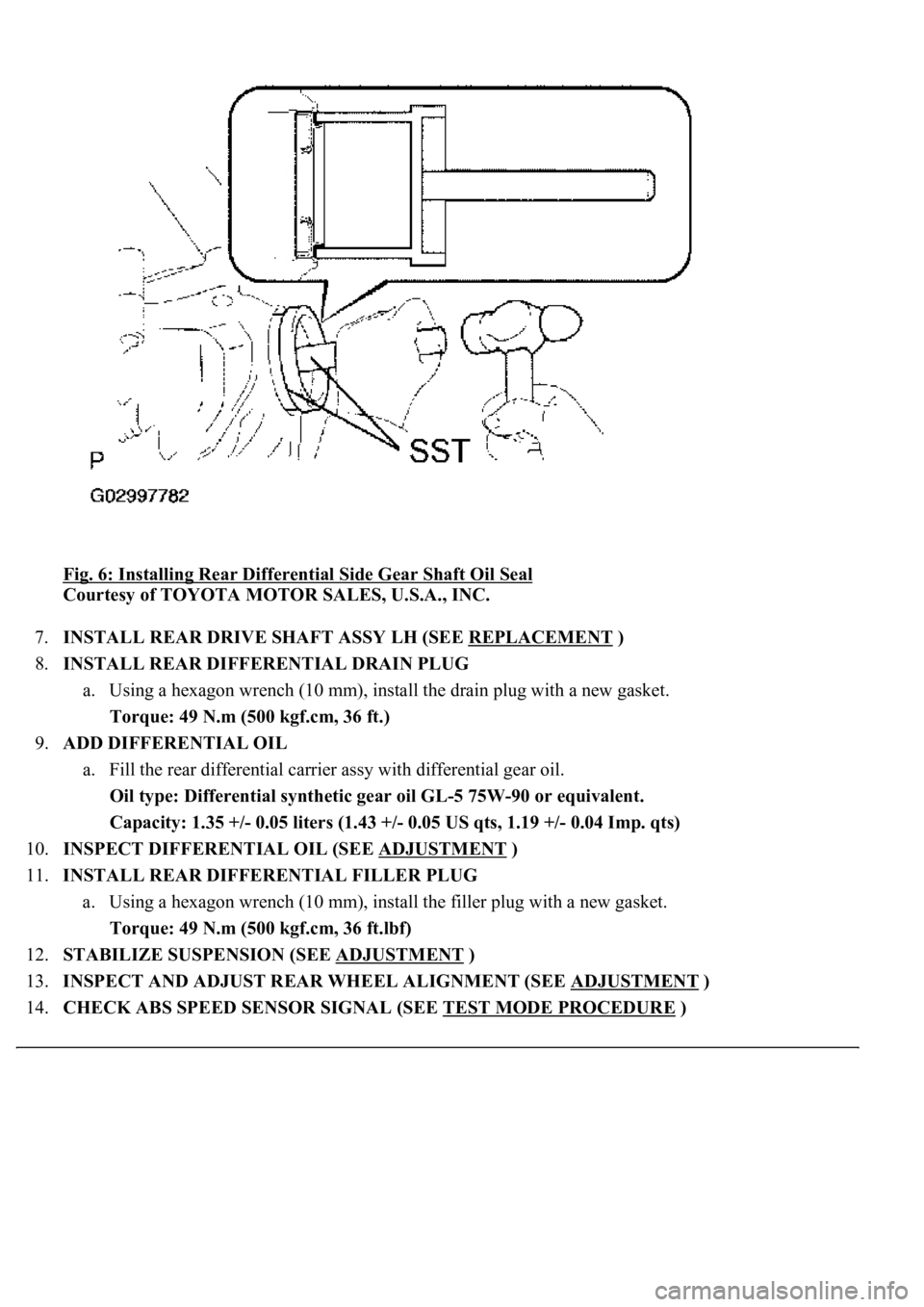
6.INSTALL REAR DIFFERENTIAL SIDE GEAR SHAFT OIL SEAL
a. Using SST and a hammer, install a new oil seal.
b. Apply MP grease to the oil seal lip.
SST 09950-70010 (09951-07150), 09223-15030
Oil seal drive in depth: 0 +/- 0.5 mm (0 +/- 0.020 in.)
Page 2045 of 4500

Fig. 6: Installing Rear Differential Side Gear Shaft Oil Seal
Courtesy of TOYOTA MOTOR SALES, U.S.A., INC.
7.INSTALL REAR DRIVE SHAFT ASSY LH (SEE REPLACEMENT
)
8.INSTALL REAR DIFFERENTIAL DRAIN PLUG
a. Using a hexagon wrench (10 mm), install the drain plug with a new gasket.
Torque: 49 N.m (500 kgf.cm, 36 ft.)
9.ADD DIFFERENTIAL OIL
a. Fill the rear differential carrier assy with differential gear oil.
Oil type: Differential synthetic gear oil GL-5 75W-90 or equivalent.
<00260044005300440046004c0057005c001d000300140011001600180003000e00120010000300130011001300180003004f004c00570048005500560003000b00140011001700160003000e00120010000300130011001300180003003800360003005400
570056000f0003001400110014001c0003000e001200100003[0.04 Imp. qts)
10.INSPECT DIFFERENTIAL OIL (SEE ADJUSTMENT
)
11.INSTALL REAR DIFFERENTIAL FILLER PLUG
a. Using a hexagon wrench (10 mm), install the filler plug with a new gasket.
Torque: 49 N.m (500 kgf.cm, 36 ft.lbf)
12.STABILIZE SUSPENSION (SEE ADJUSTMENT
)
13.INSPECT AND ADJUST REAR WHEEL ALIGNMENT (SEE ADJUSTMENT
)
14.CHECK ABS SPEED SENSOR SIGNAL (SEE TEST MODE PROCEDURE
)
Page 2046 of 4500

OVERHAUL
HINT:
See COMPONENTS
1.REMOVE REAR WHEEL
2.REMOVE EXHAUST PIPE ASSY (SEE REPLACEMENT
)
3.REMOVE FRONT FLOOR HEAT INSULATOR NO.1 (SEE OVERHAUL
)
4.REMOVE PROPELLER SHAFT HEAT INSULATOR (SEE OVERHAUL
)
5.REMOVE PROPELLER W/CENTER BEARING SHAFT ASSY (SEE OVERHAUL
)
6.REMOVE REAR DIFFERENTIAL FILLER PLUG
a. Using a hexagon wrench (10 mm), remove the filler plug and gasket.
7.REMOVE REAR DIFFERENTIAL DRAIN PLUG
a. Using a hexagon wrench (10 mm), remove the drain plug and gasket.
b. Drain the differential oil.
8.REMOVE REAR DRIVE SHAFT ASSY LH (SEE REPLACEMENT
)
9.REMOVE REAR DRIVE SHAFT ASSY RH
HINT:
Removal procedure of the RH side is the same as that of the LH side.
10.REMOVE STABILIZER BAR REAR (SEE REPLACEMENT
)
HINT:
Perform this procedure only when the rear differential mount cushion should be changed.
11.REMOVE HEIGHT CONTROL VALVE SUB-ASSY NO.2 (W/ AIR SUSPENSION) (SEE
REPLACEMENT
)
HINT:
Perform this procedure only when the rear differential mount cushion should be changed.
12.REMOVE DIFFERENTIAL CARRIER ASSY REAR
a. Support the differential carrier with a jack and wooden block.