Page 882 of 4500
Fig. 61: Removing 3 Magnets From Oil Pan
Courtesy of TOYOTA MOTOR SALES, U.S.A., INC.
c. Examine particles in pan.
1. Collect any steel chips with the removed magnets. Carefully look at the foreign objects and
particles in the pan and on the magnets to guess at the type of wear which might be found in
the transmission. Steel (magnetic) hellip bearing, gear and clutch plate wear
Brass (non-ma
gnetic) hellip bushing wear
Page 893 of 4500
Fig. 72: Installing Oil Pan With 20 Bolts To Transmission Case
Courtesy of TOYOTA MOTOR SALES, U.S.A., INC.
11.CONNECT BATTERY NEGATIVE TERMINAL
12.ADD AUTOMATIC TRANSMISSION FLUID (SEE ADJUSTMENT
)
Fluid type: ATF WS
Capacity: 4.3 liters (4.5 US qts, 3.8 Imp.qts)
13.RESET MEMORY (SEE INITIALIZATION
)
14.PERFORM INITIALIZATION (SEE INITIALIZATION
)
REPLACEMENT
<00380056004c0051004a00030044000300550044005d0052005500030045004f00440047004800030044005100470003004a00440056004e0048005700030056004600550044005300480055000f000300550048005000520059004800030044004f004f00
030057004b004800030052004f004700030029002c0033002a[ material from the gasket surfaces.
Thoroughly clean all components to remove any loose material.
Page 895 of 4500
Fig. 74: Removing 3 Magnets From Oil Pan
Courtesy of TOYOTA MOTOR SALES, U.S.A., INC.
c. Examine particles in the pan.
a. Collect any steel chips with the removed magnets. Carefully look at the foreign objects and
particles in the pan and on the magnets to guess at the type of wear which might be found in
the transmission. Steel (magnetic) hellip bearing, gear and clutch plate wear
Brass (non-ma
gnetic) hellip bushing wear
Page 912 of 4500
Fig. 90: Installing Oil Pan With 20 Bolts To Transmission Case
Courtesy of TOYOTA MOTOR SALES, U.S.A., INC.
11.CONNECT BATTERY NEGATIVE TERMINAL
12.ADD AUTOMATIC TRANSMISSION FLUID (SEE ADJUSTMENT
)
Fluid type: ATF WS
Capacity: 4.3 liters (4.5 US qts, 3.8 Imp.qts)
13.RESET MEMORY (SEE INITIALIZATION
)
14.PERFORM INITIALIZATION (SEE INITIALIZATION
)
REPLACEMENT
1.REMOVE INSTRUMENT PANEL UNDER COVER SUB-ASSY NO.2 (SEE REPLACEMENT
)
2.REMOVE INSTRUMENT PANEL GARNISH SUB-ASSY LH (SEE REPLACEMENT
)
3.REMOVE INSTRUMENT PANEL FINISH PANEL (SEE REPLACEMENT
)
4.REMOVE INSTRUMENT PANEL UNDER COVER SUB-ASSY NO.1 (SEE REPLACEMENT
)
5.REMOVE SWITCH BRACE HOLE COVER (SEE REPLACEMENT
)
Page 2042 of 4500
a. Stop the vehicle on a level place.
b. Using a hexagon wrench (10 mm), remove the rear differential filler plug and gasket.
c. Check that the oil surface is within 5 mm (0.20 in.) of the lowest position of the inner surface of the
differential filler plug opening.
Fig. 4: Inspecting And Adjusting Differential Oil
Courtesy of TOYOTA MOTOR SALES, U.S.A., INC.
d. Check for oil leakage when the oil level is low.
e. Using a hexagon wrench (10 mm), install the rear differential filler plug with a new gasket.
Torque: 49 N.m (500 kgf.cm, 36 ft.lbf)
2.ADD DIFFERENTIAL OIL
a. Using a hexagon wrench (10 mm), remove the rear differential filler plug and gasket.
b. Add oil.
Oil type: Differential synthetic gear oil GL-5 75W-90 or equivalent
Capacity: 1.35 +/- 0.05 liters (1.43 +/- 0.05 US qts, 1.19 +/- 0.04 Imp. qts)
Page 2045 of 4500

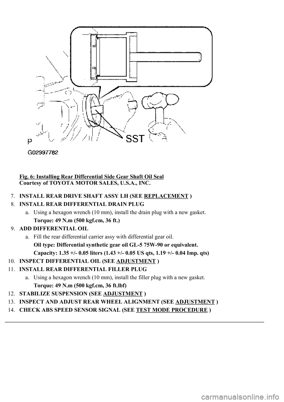
Fig. 6: Installing Rear Differential Side Gear Shaft Oil Seal
Courtesy of TOYOTA MOTOR SALES, U.S.A., INC.
7.INSTALL REAR DRIVE SHAFT ASSY LH (SEE REPLACEMENT
)
8.INSTALL REAR DIFFERENTIAL DRAIN PLUG
a. Using a hexagon wrench (10 mm), install the drain plug with a new gasket.
Torque: 49 N.m (500 kgf.cm, 36 ft.)
9.ADD DIFFERENTIAL OIL
a. Fill the rear differential carrier assy with differential gear oil.
Oil type: Differential synthetic gear oil GL-5 75W-90 or equivalent.
<00260044005300440046004c0057005c001d000300140011001600180003000e00120010000300130011001300180003004f004c00570048005500560003000b00140011001700160003000e00120010000300130011001300180003003800360003005400
570056000f0003001400110014001c0003000e001200100003[0.04 Imp. qts)
10.INSPECT DIFFERENTIAL OIL (SEE ADJUSTMENT
)
11.INSTALL REAR DIFFERENTIAL FILLER PLUG
a. Using a hexagon wrench (10 mm), install the filler plug with a new gasket.
Torque: 49 N.m (500 kgf.cm, 36 ft.lbf)
12.STABILIZE SUSPENSION (SEE ADJUSTMENT
)
13.INSPECT AND ADJUST REAR WHEEL ALIGNMENT (SEE ADJUSTMENT
)
14.CHECK ABS SPEED SENSOR SIGNAL (SEE TEST MODE PROCEDURE
)
Page 2177 of 4500

a. Fill the rear differential carrier assy with differential gear oil equivalent.
Oil type: Differential synthetic gear oil GL-5 75W-90 or equivalent
Capacity: 1.35 +/- 0.05 liters (1.43 +/- 0.05 US qts, 1.19 +/- 0.04 Imp. qts)
67.INSPECT DIFFERENTIAL OIL (SEE ADJUSTMENT
)
68.INSTALL REAR DIFFERENTIAL FILLER PLUG
a. Using a hexagon wrench (10 mm), install the filler plug with a new gasket.
Torque: 49 N.m (500 kgf.cm, 36 ft.lbf)
69.INSTALL REAR DRIVE SHAFT ASSY LH (SEE REPLACEMENT
)
70.INSTALL REAR DRIVE SHAFT ASSY RH
HINT:
Installation procedure of the RH side is the same as that of the LH side.
71.INSTALL FRONT FLOOR HEAT INSULATOR NO.1
a. Install the front floor heat insulator No.1 with the 4 bolts.
Torque: 5.4 N.m (55 kgf.cm, 48 in..lbf)
72.INSTALL REAR WHEEL
a. Install the rear wheel with the 5 nuts.
Torque: 103 N.m (1,050 kgf.cm, 76 ft.lbf)
73. Install the ornament with the 10 bolts.
Torque: 20 N.m (204 kgf.cm, 15 ft.lbf)
74.INSTALL PROPELLER W/CENTER BEARING SHAFT ASSY (SEE OVERHAUL
)
75.FULLY TIGHTEN CENTER SUPPORT BEARING ASSY NO.1 (SEE OVERHAUL
)
SST 09922-10010
76.INSPECT AND ADJUST NO.2 AND NO.3 JOINT ANGLE (SEE OVERHAUL
)
77.INSTALL PROPELLER SHAFT HEAT INSULATOR (SEE OVERHAUL
)
78.INSTALL EXHAUST PIPE ASSY (SEE REPLACEMENT
)
79.INSTALL OXYGEN SENSOR (SEE REPLACEMENT
)
80.INSPECT AND ADJUST REAR WHEEL ALIGNMENT (SEE ADJUSTMENT
)
81.ADJUST VEHICLE HEIGHT (W/ AIR SUSPENSION) (SEE ON
-VEHICLE INSPECTION )
82.INSPECT HEADLIGHT AIM ONLY (SEE ADJUSTMENT
)
83.CHECK ABS SPEED SENSOR SIGNAL (SEE TEST MODE PROCEDURE
)
84.INSPECT AIR LEAK (W/ AIR SUSPENSION) (SEE REPLACEMENT
)
HINT:
Perform this operation onl
y when the rear differential mount cushion is replaced.
Page 4110 of 4500
Fig. 11: Covering Disconnected Pipe And Connector With Plastic Bag
Courtesy of TOYOTA MOTOR SALES, U.S.A., INC.
f. Observe these precautions when connecting the fuel tube connector (quick type).
1. Check that there is no damage or foreign matter on the part of the pipe that contacts the
connector.
2. Align the axis of the connector with the axis of the pipe. Push the pipe into the connector
until the connector makes a `click' sound. If the connection is too tight, apply a small amount
of fresh engine oil on the tip of the pipe.
Fig. 12: Aligning Axis Of Connector With Axis Of Pipe
Courtesy of TOYOTA MOTOR SALES, U.S.A., INC.
3. After connecting the pipe and connector, try to pull them apart to confirm that they are
securely connected.
4. Install the No. 1 fuel pipe clamp to the connector.