2003 LEXUS LS430 low oil pressure
[x] Cancel search: low oil pressurePage 1847 of 4500
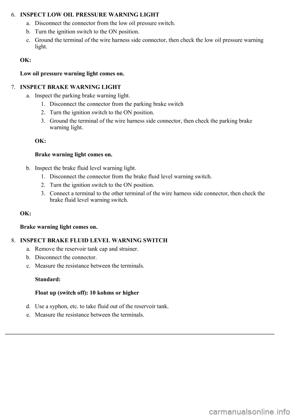
6.INSPECT LOW OIL PRESSURE WARNING LIGHT
a. Disconnect the connector from the low oil pressure switch.
b. Turn the ignition switch to the ON position.
c. Ground the terminal of the wire harness side connector, then check the low oil pressure warning
light.
OK:
Low oil pressure warning light comes on.
7.INSPECT BRAKE WARNING LIGHT
a. Inspect the parking brake warning light.
1. Disconnect the connector from the parking brake switch
2. Turn the ignition switch to the ON position.
3. Ground the terminal of the wire harness side connector, then check the parking brake
warning light.
OK:
Brake warning light comes on.
b. Inspect the brake fluid level warning light.
1. Disconnect the connector from the brake fluid level warning switch.
2. Turn the ignition switch to the ON position.
3. Connect a terminal to the other terminal of the wire harness side connector, then check the
brake fluid level warning switch.
OK:
Brake warning light comes on.
8.INSPECT BRAKE FLUID LEVEL WARNING SWITCH
a. Remove the reservoir tank cap and strainer.
b. Disconnect the connector.
c. Measure the resistance between the terminals.
Standard:
Float up (switch off): 10 kohms or higher
d. Use a syphon, etc. to take fluid out of the reservoir tank.
e. Measure the resistance between the terminals.
Page 1850 of 4500
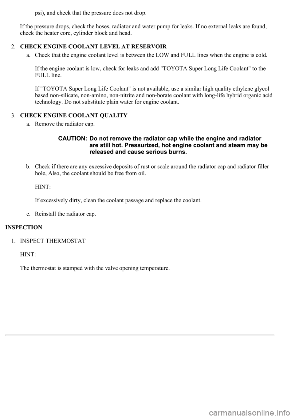
psi), and check that the pressure does not drop.
If the pressure drops, check the hoses, radiator and water pump for leaks. If no external leaks are found,
check the heater core, cylinder block and head.
2.CHECK ENGINE COOLANT LEVEL AT RESERVOIR
a. Check that the engine coolant level is between the LOW and FULL lines when the engine is cold.
If the engine coolant is low, check for leaks and add "TOYOTA Super Long Life Coolant" to the
FULL line.
If "TOYOTA Super Long Life Coolant" is not available, use a similar high quality ethylene glycol
based non-silicate, non-amino, non-nitrite and non-borate coolant with long-life hybrid organic acid
technology. Do not substitute plain water for engine coolant.
3.CHECK ENGINE COOLANT QUALITY
a. Remove the radiator cap.
b. Check if there are any excessive deposits of rust or scale around the radiator cap and radiator filler
hole, Also, the coolant should be free from oil.
HINT:
If excessively dirty, clean the coolant passage and replace the coolant.
c. Reinstall the radiator cap.
INSPECTION
1. INSPECT THERMOSTAT
HINT:
The thermostat is stamped with the valve openin
g temperature.
Page 2634 of 4500
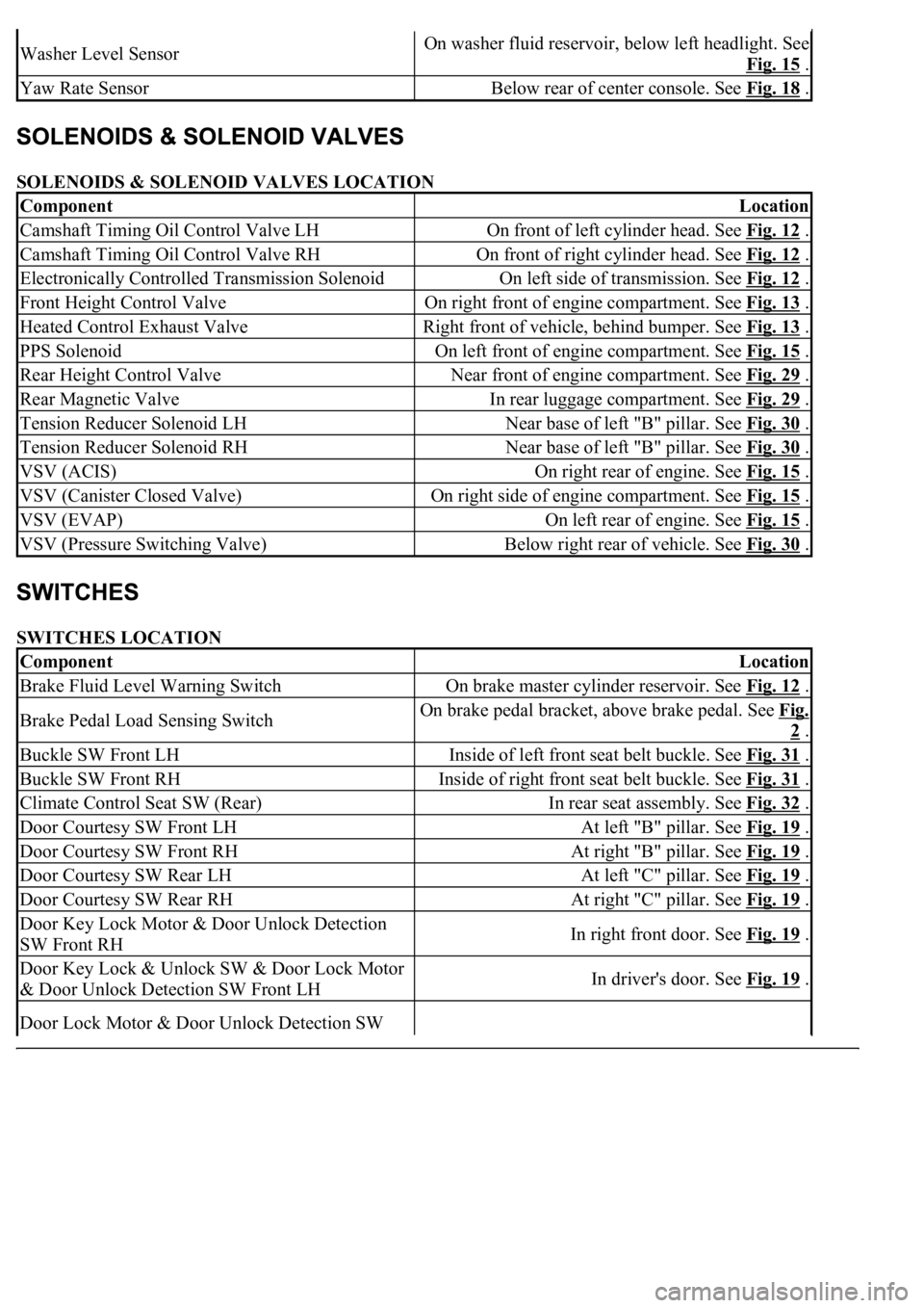
SOLENOIDS & SOLENOID VALVES LOCATION
SWITCHES LOCATION
Washer Level SensorOn washer fluid reservoir, below left headlight. See
Fig. 15
.
Yaw Rate SensorBelow rear of center console. See Fig. 18 .
ComponentLocation
Camshaft Timing Oil Control Valve LHOn front of left cylinder head. See Fig. 12 .
Camshaft Timing Oil Control Valve RHOn front of right cylinder head. See Fig. 12 .
Electronically Controlled Transmission SolenoidOn left side of transmission. See Fig. 12 .
Front Height Control ValveOn right front of engine compartment. See Fig. 13 .
Heated Control Exhaust ValveRight front of vehicle, behind bumper. See Fig. 13 .
PPS SolenoidOn left front of engine compartment. See Fig. 15 .
Rear Height Control ValveNear front of engine compartment. See Fig. 29 .
Rear Magnetic ValveIn rear luggage compartment. See Fig. 29 .
Tension Reducer Solenoid LHNear base of left "B" pillar. See Fig. 30 .
Tension Reducer Solenoid RHNear base of left "B" pillar. See Fig. 30 .
VSV (ACIS)On right rear of engine. See Fig. 15 .
VSV (Canister Closed Valve)On right side of engine compartment. See Fig. 15 .
VSV (EVAP)On left rear of engine. See Fig. 15 .
VSV (Pressure Switching Valve)Below right rear of vehicle. See Fig. 30 .
ComponentLocation
Brake Fluid Level Warning SwitchOn brake master cylinder reservoir. See Fig. 12 .
Brake Pedal Load Sensing SwitchOn brake pedal bracket, above brake pedal. See Fig.
2 .
Buckle SW Front LHInside of left front seat belt buckle. See Fig. 31 .
Buckle SW Front RHInside of right front seat belt buckle. See Fig. 31 .
Climate Control Seat SW (Rear)In rear seat assembly. See Fig. 32 .
Door Courtesy SW Front LHAt left "B" pillar. See Fig. 19 .
Door Courtesy SW Front RHAt right "B" pillar. See Fig. 19 .
Door Courtesy SW Rear LHAt left "C" pillar. See Fig. 19 .
Door Courtesy SW Rear RHAt right "C" pillar. See Fig. 19 .
Door Key Lock Motor & Door Unlock Detection
SW Front RHIn right front door. See Fig. 19 .
Door Key Lock & Unlock SW & Door Lock Motor
& Door Unlock Detection SW Front LHIn driver's door. See Fig. 19 .
Door Lock Motor & Door Unlock Detection SW
Page 2635 of 4500
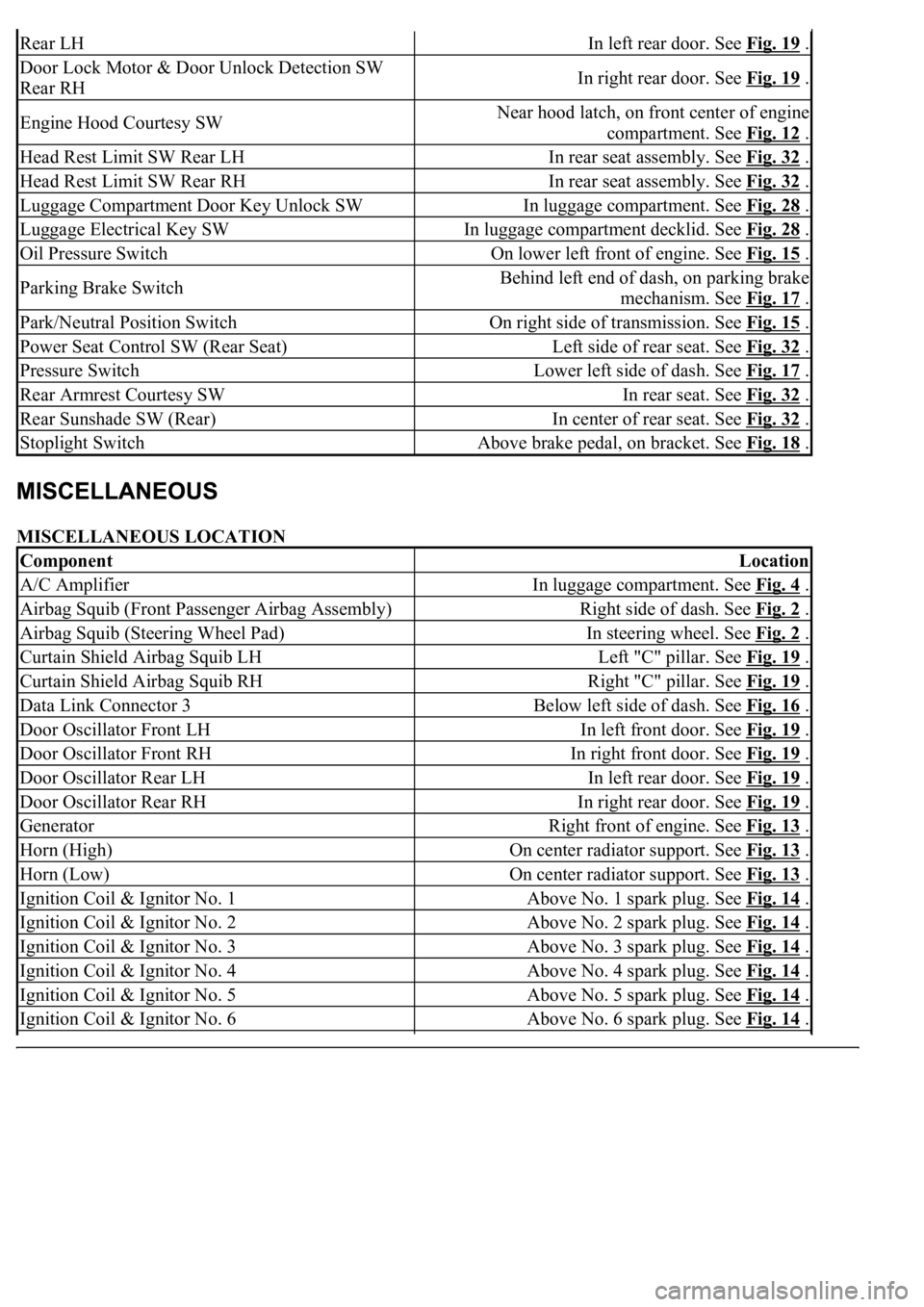
MISCELLANEOUS LOCATION
Rear LHIn left rear door. See Fig. 19 .
Door Lock Motor & Door Unlock Detection SW
Rear RHIn right rear door. See Fig. 19 .
Engine Hood Courtesy SWNear hood latch, on front center of engine
compartment. See Fig. 12
.
Head Rest Limit SW Rear LHIn rear seat assembly. See Fig. 32 .
Head Rest Limit SW Rear RHIn rear seat assembly. See Fig. 32 .
Luggage Compartment Door Key Unlock SWIn luggage compartment. See Fig. 28 .
Luggage Electrical Key SWIn luggage compartment decklid. See Fig. 28 .
Oil Pressure SwitchOn lower left front of engine. See Fig. 15 .
Parking Brake SwitchBehind left end of dash, on parking brake
mechanism. See Fig. 17
.
Park/Neutral Position SwitchOn right side of transmission. See Fig. 15 .
Power Seat Control SW (Rear Seat)Left side of rear seat. See Fig. 32 .
Pressure SwitchLower left side of dash. See Fig. 17 .
Rear Armrest Courtesy SWIn rear seat. See Fig. 32 .
Rear Sunshade SW (Rear)In center of rear seat. See Fig. 32 .
Stoplight SwitchAbove brake pedal, on bracket. See Fig. 18 .
ComponentLocation
A/C AmplifierIn luggage compartment. See Fig. 4 .
Airbag Squib (Front Passenger Airbag Assembly)Right side of dash. See Fig. 2 .
Airbag Squib (Steering Wheel Pad)In steering wheel. See Fig. 2 .
Curtain Shield Airbag Squib LHLeft "C" pillar. See Fig. 19 .
Curtain Shield Airbag Squib RHRight "C" pillar. See Fig. 19 .
Data Link Connector 3Below left side of dash. See Fig. 16 .
Door Oscillator Front LHIn left front door. See Fig. 19 .
Door Oscillator Front RHIn right front door. See Fig. 19 .
Door Oscillator Rear LHIn left rear door. See Fig. 19 .
Door Oscillator Rear RHIn right rear door. See Fig. 19 .
GeneratorRight front of engine. See Fig. 13 .
Horn (High)On center radiator support. See Fig. 13 .
Horn (Low)On center radiator support. See Fig. 13 .
Ignition Coil & Ignitor No. 1Above No. 1 spark plug. See Fig. 14 .
Ignition Coil & Ignitor No. 2Above No. 2 spark plug. See Fig. 14 .
Ignition Coil & Ignitor No. 3Above No. 3 spark plug. See Fig. 14 .
Ignition Coil & Ignitor No. 4Above No. 4 spark plug. See Fig. 14 .
Ignition Coil & Ignitor No. 5Above No. 5 spark plug. See Fig. 14 .
Ignition Coil & Ignitor No. 6Above No. 6 spark plug. See Fig. 14 .
Page 2669 of 4500
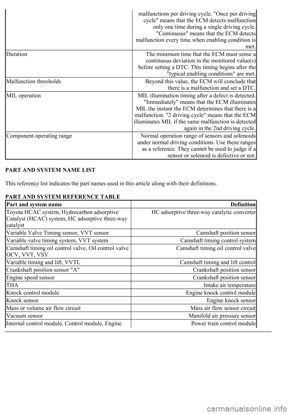
PART AND SYSTEM NAME LIST
This reference list indicates the part names used in this article along with their definitions.
PART AND SYSTEM REFERENCE TABLE
malfunctions per driving cycle. "Once per driving
cycle" means that the ECM detects malfunction
only one time during a single driving cycle.
"Continuous" means that the ECM detects
malfunction every time when enabling condition is
met.
DurationThe minimum time that the ECM must sense a
continuous deviation in the monitored value(s)
before setting a DTC. This timing begins after the
"typical enabling conditions" are met.
Malfunction thresholdsBeyond this value, the ECM will conclude that
there is a malfunction and set a DTC.
MIL operationMIL illumination timing after a defect is detected.
"Immediately" means that the ECM illuminates
MIL the instant the ECM determines that there is a
malfunction. "2 driving cycle" means that the ECM
illuminates MIL if the same malfunction is detected
again in the 2nd driving cycle.
Component operating rangeNormal operation range of sensors and solenoids
under normal driving conditions. Use these ranges
as a reference. They cannot be used to judge if a
sensor or solenoid is defective or not.
Part and system nameDefinition
Toyota HCAC system, Hydrocarbon adsorptive
Catalyst (HCAC) system, HC adsorptive three-way
catalystHC adsorptive three-way catalytic converter
Variable Valve Timing sensor, VVT sensorCamshaft position sensor
Variable valve timing system, VVT systemCamshaft timing control system
Camshaft timing oil control valve, Oil control valve
OCV, VVT, VSVCamshaft timing oil control valve
Variable timing and lift, VVTLCamshaft timing and lift control
Crankshaft position sensor "A"Crankshaft position sensor
Engine speed sensorCrankshaft position sensor
THAIntake air temperature
Knock control moduleEngine knock control module
Knock sensorEngine knock sensor
Mass or volume air flow circuitMass air flow sensor circuit
Vacuum sensorManifold air pressure sensor
Internal control module, Control module, Engine Power train control module
Page 2765 of 4500
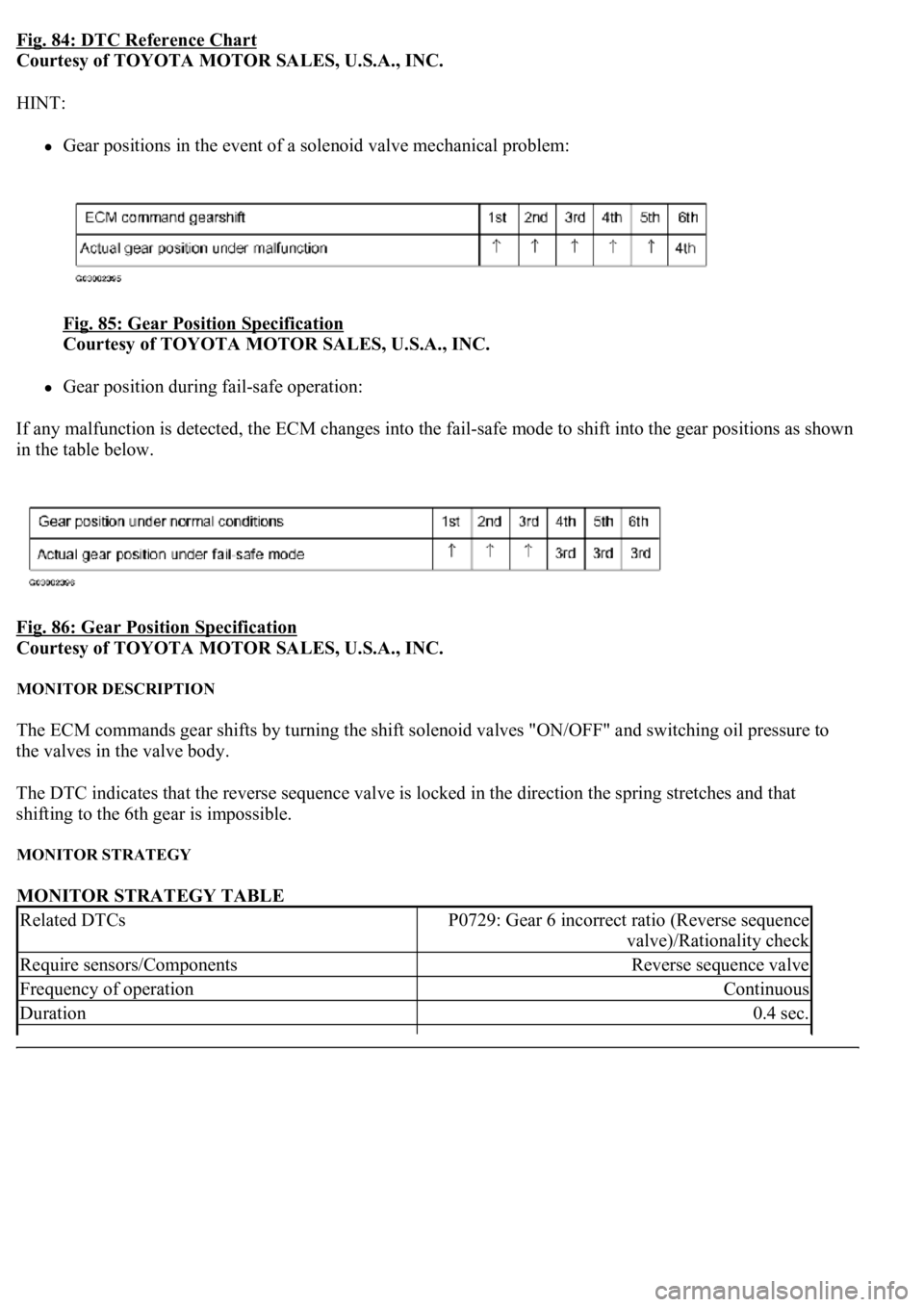
Fig. 84: DTC Reference Chart
Courtesy of TOYOTA MOTOR SALES, U.S.A., INC.
HINT:
Gear positions in the event of a solenoid valve mechanical problem:
Fig. 85: Gear Position Specification
Courtesy of TOYOTA MOTOR SALES, U.S.A., INC.
Gear position during fail-safe operation:
If any malfunction is detected, the ECM changes into the fail-safe mode to shift into the gear positions as shown
in the table below.
Fig. 86: Gear Position Specification
Courtesy of TOYOTA MOTOR SALES, U.S.A., INC.
MONITOR DESCRIPTION
The ECM commands gear shifts by turning the shift solenoid valves "ON/OFF" and switching oil pressure to
the valves in the valve body.
The DTC indicates that the reverse sequence valve is locked in the direction the spring stretches and that
shifting to the 6th gear is impossible.
MONITOR STRATEGY
MONITOR STRATEGY TABLE
Related DTCsP0729: Gear 6 incorrect ratio (Reverse sequence
valve)/Rationality check
Require sensors/ComponentsReverse sequence valve
Frequency of operationContinuous
Duration0.4 sec.
Page 2820 of 4500
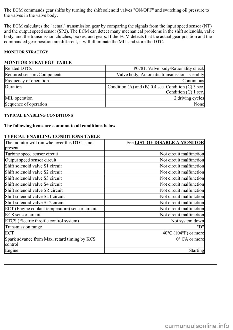
The ECM commands gear shifts by turning the shift solenoid valves "ON/OFF" and switching oil pressure to
the valves in the valve body.
The ECM calculates the "actual" transmission gear by comparing the signals from the input speed sensor (NT)
and the output speed sensor (SP2). The ECM can detect many mechanical problems in the shift solenoids, valve
body, and the transmission clutches, brakes, and gears. If the ECM detects that the actual gear position and the
commanded gear position are different, it will illuminate the MIL and store the DTC.
MONITOR STRATEGY
MONITOR STRATEGY TABLE
TYPICAL ENABLING CONDITIONS
The following items are common to all conditions below.
TYPICAL ENABLING CONDITIONS TABLE
Related DTCsP0781: Valve body/Rationality check
Required sensors/ComponentsValve body, Automatic transmission assembly
Frequency of operationContinuous
Duration<0026005200510047004c0057004c005200510003000b0024000c00030044005100470003000b0025000c00030013001100170003005600480046001100030026005200510047004c0057004c005200510003000b0026000c00030016000300560048004600
110003[
Condition (C) 1 sec.
MIL operation2 driving cycles
Sequence of operationNone
The monitor will run whenever this DTC is not
present.See LIST OF DISABLE A MONITOR
Turbine speed sensor circuitNot circuit malfunction
Output speed sensor circuitNot circuit malfunction
Shift solenoid valve S1 circuitNot circuit malfunction
Shift solenoid valve S2 circuitNot circuit malfunction
Shift solenoid valve S3 circuitNot circuit malfunction
Shift solenoid valve S4 circuitNot circuit malfunction
Shift solenoid valve SR circuitNot circuit malfunction
Shift solenoid valve SL1 circuitNot circuit malfunction
Shift solenoid valve SL2 circuitNot circuit malfunction
ECT (Engine coolant temperature) sensor circuitNot circuit malfunction
KCS sensor circuitNot circuit malfunction
ETCS (Electric throttle control system)Not system down
Transmission range"D"
ECT40°C (104°F) or more
Spark advance from Max. retard timing by KCS
control0° CA or more
EngineStarting
Page 3284 of 4500
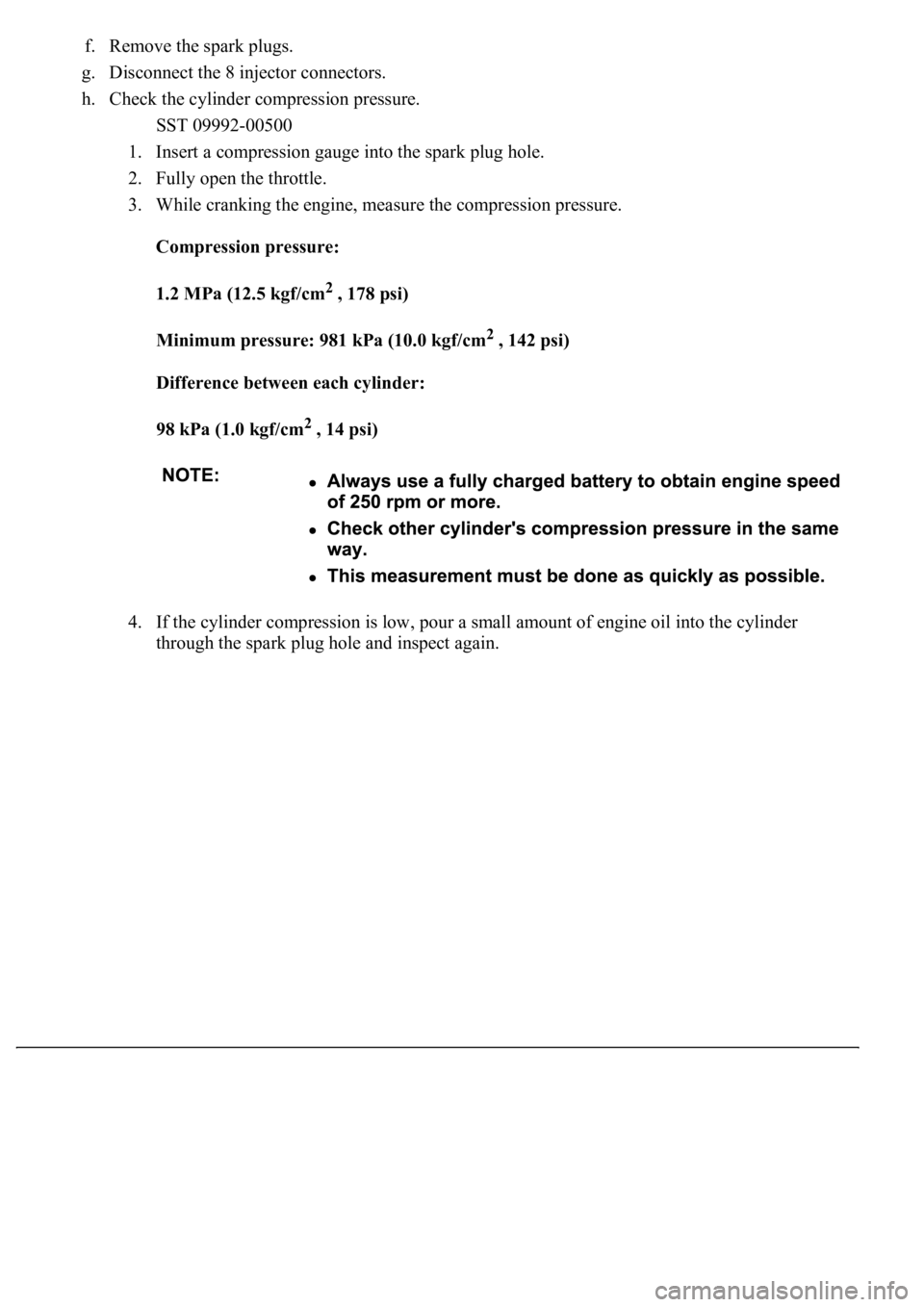
f. Remove the spark plugs.
g. Disconnect the 8 injector connectors.
h. Check the cylinder compression pressure.
SST 09992-00500
1. Insert a compression gauge into the spark plug hole.
2. Fully open the throttle.
3. While cranking the engine, measure the compression pressure.
Compression pressure:
1.2 MPa (12.5 kgf/cm
2 , 178 psi)
Minimum pressure: 981 kPa (10.0 kgf/cm
2 , 142 psi)
Difference between each cylinder:
98 kPa (1.0 kgf/cm
2 , 14 psi)
4. If the cylinder compression is low, pour a small amount of engine oil into the cylinder
throu
gh the spark plug hole and inspect again.